RU2439373C1 - Stage of downhole multistage rotary pump - Google Patents
Stage of downhole multistage rotary pump Download PDFInfo
- Publication number
- RU2439373C1 RU2439373C1 RU2010115517/06A RU2010115517A RU2439373C1 RU 2439373 C1 RU2439373 C1 RU 2439373C1 RU 2010115517/06 A RU2010115517/06 A RU 2010115517/06A RU 2010115517 A RU2010115517 A RU 2010115517A RU 2439373 C1 RU2439373 C1 RU 2439373C1
- Authority
- RU
- Russia
- Prior art keywords
- grooves
- impeller
- stage
- cover
- rotary pump
- Prior art date
Links
- 230000013011 mating Effects 0.000 claims description 2
- 230000000694 effects Effects 0.000 abstract description 6
- 239000000126 substance Substances 0.000 abstract 1
- XLYOFNOQVPJJNP-UHFFFAOYSA-N water Substances O XLYOFNOQVPJJNP-UHFFFAOYSA-N 0.000 abstract 1
- 239000012530 fluid Substances 0.000 description 13
- 230000015572 biosynthetic process Effects 0.000 description 11
- 239000007788 liquid Substances 0.000 description 6
- 239000006185 dispersion Substances 0.000 description 3
- 230000002093 peripheral effect Effects 0.000 description 2
- 238000005086 pumping Methods 0.000 description 2
- 238000009825 accumulation Methods 0.000 description 1
- 230000003247 decreasing effect Effects 0.000 description 1
- 230000002708 enhancing effect Effects 0.000 description 1
- 238000007654 immersion Methods 0.000 description 1
- 238000000034 method Methods 0.000 description 1
- 239000003208 petroleum Substances 0.000 description 1
Images
Landscapes
- Structures Of Non-Positive Displacement Pumps (AREA)
Abstract
Description
Изобретение относится к нефтяному машиностроению, точнее - к узлам скважинных насосов для откачки пластовой жидкости.The invention relates to the field of petroleum engineering, more specifically, to nodes of downhole pumps for pumping formation fluid.
Известна ступень погружного центробежного насоса, содержащая направляющий аппарат с крышкой и сопряженное с ней с зазором рабочее колесо с внутренними каналами и пазами (ячейками) со стороны крышки - патент RU №2138691 С1 на «Ступень погружного многоступенчатого насоса», опубл. 1999.09.27.A known step of a submersible centrifugal pump, comprising a guiding apparatus with a cover and an impeller conjugated with it with a clearance with internal channels and grooves (cells) from the side of the cover - patent RU No. 2138691 C1 to "Stage of a submersible multi-stage pump", publ. 1999.09.27.
По своим признакам и достигаемому результату эта ступень погружного центробежного насоса наиболее близка к заявляемой и принята за прототип.According to its characteristics and the achieved result, this stage of a submersible centrifugal pump is closest to the claimed one and is taken as a prototype.
В этой ступени на периферии рабочего колеса на боковой его поверхности со стороны крышки направляющего аппарата установлены трехсторонние пазы (ячейки), открытые со стороны крышки и с периферийной стороны рабочего колеса, с плавным уменьшением их глубины до нуля в направлении оси ступени. Пазы (ячейки) такой ступени воздействуют на поток перекачиваемой жидкости посредством его диспергации (дробления), что при скорости вращения рабочего колеса порядка 3000 об/мин и малом (6…20 мм) шаге расположения пазов малоэффективно.In this stage, on the periphery of the impeller, on its side surface from the side of the cover of the guide apparatus, three-sided grooves (cells) are installed, open on the side of the cover and on the peripheral side of the impeller, with a smooth decrease in their depth to zero in the direction of the axis of the step. The grooves (cells) of such a stage affect the flow of the pumped liquid through its dispersion (crushing), which at an impeller rotation speed of about 3000 rpm and a small (6 ... 20 mm) groove spacing is ineffective.
Кроме того, входящая в зазор между крышкой и рабочим колесом пластовая жидкость, попадая на плавно уменьшающиеся по глубине (пологие) участки пазов, отражается от них на крышку с образованием гидравлического затвора, препятствующего радиальному движению пластовой жидкости, что снижает диспергирующее действие ступени, приближая его к простому механическому воздействию периферийных участков пазов на перекачиваемую жидкость.In addition, the formation fluid entering the gap between the cover and the impeller, entering the grooves gradually decreasing in depth (gently sloping), is reflected from them onto the cover with the formation of a hydraulic shutter preventing the radial movement of the formation fluid, which reduces the dispersing effect of the stage, bringing it closer to the simple mechanical effect of the peripheral sections of the grooves on the pumped liquid.
Недостатки известной ступени заключаются в малом коэффициенте полезного действия (кпд) и ограниченном диапазоне воздействия на поток перекачиваемой жидкости, т.к. положительный результат наблюдается только при малых подачах ступени.The disadvantages of the known stage are the low efficiency (efficiency) and a limited range of effects on the flow of the pumped liquid, because a positive result is observed only at low feed rates.
Техническим результатом предложенного изобретения является повышение кпд ступени и увеличение диапазона ее воздействия на поток перекачиваемой жидкости.The technical result of the proposed invention is to increase the efficiency of the stage and increase the range of its impact on the flow of the pumped liquid.
Указанный технический результат обеспечивается тем, что в ступени погружного центробежного насоса, выполненной в виде направляющего аппарата с крышкой и сопряженного с ней с зазором рабочего колеса с внутренними каналами и пазами со стороны крышки согласно изобретению рабочее колесо выполнено с кольцевым резервуаром напротив пазов, торцевые стенки которых расположены вдоль оси ступени.The specified technical result is ensured by the fact that in the step of a submersible centrifugal pump, made in the form of a guide apparatus with a cover and mating with it a clearance of the impeller with internal channels and grooves on the side of the lid according to the invention, the impeller is made with an annular reservoir opposite the grooves, the end walls of which located along the axis of the step.
Сущность предложенного технического решения поясняется чертежами, The essence of the proposed technical solution is illustrated by drawings,
где на фиг.1 представлена ступень погружного центробежного насоса в осевом сечении;where in Fig.1 shows the stage of a submersible centrifugal pump in axial section;
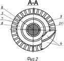
на фиг.2 - ступень в сечении А-А фиг.1;figure 2 is a step in section aa of figure 1;
тонкими линиями показаны смежные узлы ступени.thin lines show adjacent nodes of the step.
Ступень погружного центробежного насоса (фиг.1) содержит направляющий аппарат 1 с крышкой 2 и сопряженное с ней с зазором Б рабочее колесо 3 с внутренними всасывающе-нагнетательными каналами 4 и пазами 5 со стороны крышки 2.The submersible centrifugal pump stage (Fig. 1) contains a guiding
Рабочее колесо 3 выполнено с кольцевым резервуаром 6, расположенным напротив пазов 5, открытым в направлении крышки 2 (что позволило использовать кольцевой резервуар для накопления пластовой жидкости).The
Пазы 5 выполнены с торцевыми стенками 7, расположенными вдоль оси 8 ступени (что позволило увеличить длину пазов 5 и, следовательно, их емкость с увеличением центробежного действия пластовой жидкости в них, в том числе за счет суммирования с центробежным действием пластовой жидкости из резервуара вдоль пазов при работе ступени).The
В процессе погружения насоса в пластовую жидкость последняя заполняет все пустоты насоса и, следовательно, ступени.In the process of immersion of the pump in the reservoir fluid, the latter fills all the voids of the pump and, therefore, the stage.
При работе насоса в процессе вращения рабочего колеса 3 происходит всасывание пластовой жидкости каналами 4 и нагнетание ее в виде потока В (показано стрелкой). Одновременно с этим происходят импульсные выбросы жидкости из пазов 5 под действием центробежных сил в поток В до достижения примерно равновесного состояния между ними. При этом в резервуаре 6 и пазах 5 со стороны оси 8 ступени возникает разряжение.When the pump is in operation during the rotation of the
Одновременно часть потока В через зазор Б возвращается в зону разряжения резервуара 6, а из него через (поверх) торцевые(х) стенки(ок) 7 в зону разряжения пазов 5 и, присоединяясь к жидкости последних, возрастающей центробежной силой частично вновь вбрасывается импульсами в поток В, усиливая энергию его движения и диспергацию.At the same time, part of the flow B through the gap B returns to the discharge zone of the
Рабочее колесо 3 с торцевыми стенками 7 в пазах 5, исключая образование гидравлического затвора в зазоре Б, эффективно при перекачке пластовой жидкости как при малых, так и при значительных давлениях в потоке В.The
Проведенные испытания ступени по изобретению на модели 5-25 показали увеличение ее кпд по сравнению со ступенью-прототипом при подаче пластовой жидкости 10-40 м3 в сутки и максимальное повышение кпд до 7% при подаче 30 м3 в сутки.The tests of the stage according to the invention on model 5-25 showed an increase in its efficiency compared to the prototype stage when the formation fluid is supplied 10-40 m 3 per day and the maximum increase in efficiency is up to 7% when 30 m 3 is supplied.
Ступень погружного центробежного насоса благодаря возросшему центробежному воздействию пластовой жидкости из резервуара и пазов рабочего колеса на поток, нагнетаемый его каналами в направляющий аппарат, характеризуется по сравнению с прототипом повышенным кпд и расширенным диапазоном воздействия, в том числе и диспергации на поток перекачиваемой пластовой жидкости.Due to the increased centrifugal effect of the formation fluid from the reservoir and the grooves of the impeller on the flow pumped by its channels into the guiding apparatus, the step of the submersible centrifugal pump is characterized in comparison with the prototype by an increased efficiency and an extended range of exposure, including dispersion into the flow of the pumped formation fluid.
Claims (2)
Priority Applications (1)
| Application Number | Priority Date | Filing Date | Title |
|---|---|---|---|
| RU2010115517/06A RU2439373C1 (en) | 2010-04-19 | 2010-04-19 | Stage of downhole multistage rotary pump |
Applications Claiming Priority (1)
| Application Number | Priority Date | Filing Date | Title |
|---|---|---|---|
| RU2010115517/06A RU2439373C1 (en) | 2010-04-19 | 2010-04-19 | Stage of downhole multistage rotary pump |
Publications (2)
| Publication Number | Publication Date |
|---|---|
| RU2010115517A RU2010115517A (en) | 2011-10-27 |
| RU2439373C1 true RU2439373C1 (en) | 2012-01-10 |
Family
ID=44997740
Family Applications (1)
| Application Number | Title | Priority Date | Filing Date |
|---|---|---|---|
| RU2010115517/06A RU2439373C1 (en) | 2010-04-19 | 2010-04-19 | Stage of downhole multistage rotary pump |
Country Status (1)
| Country | Link |
|---|---|
| RU (1) | RU2439373C1 (en) |
Families Citing this family (1)
| Publication number | Priority date | Publication date | Assignee | Title |
|---|---|---|---|---|
| CN110834536B (en) * | 2018-08-19 | 2025-01-17 | 传孚科技(厦门)有限公司 | An engineering vehicle |
Citations (4)
| Publication number | Priority date | Publication date | Assignee | Title |
|---|---|---|---|---|
| US3070026A (en) * | 1958-12-03 | 1962-12-25 | Tait Mfg Co The | Pumps |
| US4120606A (en) * | 1975-10-30 | 1978-10-17 | Klein, Schanzlin & Becker Aktiengesellschaft | Submersible motor pump |
| RU2138691C1 (en) * | 1997-11-25 | 1999-09-27 | Рабинович Александр Исаакович | Stage of submersible multi-stage pump |
| RU2196256C2 (en) * | 2001-03-23 | 2003-01-10 | Открытое акционерное общество "Борец" | Centrifugal multi-stage pump impeller |
-
2010
- 2010-04-19 RU RU2010115517/06A patent/RU2439373C1/en not_active IP Right Cessation
Patent Citations (4)
| Publication number | Priority date | Publication date | Assignee | Title |
|---|---|---|---|---|
| US3070026A (en) * | 1958-12-03 | 1962-12-25 | Tait Mfg Co The | Pumps |
| US4120606A (en) * | 1975-10-30 | 1978-10-17 | Klein, Schanzlin & Becker Aktiengesellschaft | Submersible motor pump |
| RU2138691C1 (en) * | 1997-11-25 | 1999-09-27 | Рабинович Александр Исаакович | Stage of submersible multi-stage pump |
| RU2196256C2 (en) * | 2001-03-23 | 2003-01-10 | Открытое акционерное общество "Борец" | Centrifugal multi-stage pump impeller |
Also Published As
| Publication number | Publication date |
|---|---|
| RU2010115517A (en) | 2011-10-27 |
Similar Documents
| Publication | Publication Date | Title |
|---|---|---|
| KR101695444B1 (en) | Pump | |
| JP7258852B2 (en) | Pump and method of pumping fluid | |
| RU2439373C1 (en) | Stage of downhole multistage rotary pump | |
| JP2009068458A (en) | Fuel pump | |
| DK2486283T3 (en) | The pump impeller | |
| RU2514469C1 (en) | Multistage centrifugal pump distributor | |
| CN106194776B (en) | A kind of deep well pump of band from sand discharge structure | |
| WO2011081575A1 (en) | Submersible pump stage | |
| JP4832156B2 (en) | Fuel pump | |
| RU2376500C2 (en) | Impeller of submerged centrifugal pump stage | |
| RU2372529C1 (en) | Anti-cavitation impeller | |
| RU2435075C2 (en) | Pumping unit and pumping system in which it is used | |
| KR101218502B1 (en) | Oil pump | |
| CN109964043A (en) | Spiral impeller | |
| RU2402695C1 (en) | Distributor of radial-flow multistage pump | |
| CN103380302B (en) | Oil pump | |
| KR200442699Y1 (en) | Centrifugal pump | |
| RU211349U1 (en) | Centrifugal Soil Pump | |
| RU57395U1 (en) | GUIDING DEVICE FOR STEP OF SUBMERSIBLE CENTRIFUGAL PUMP | |
| RU205750U1 (en) | Impeller of submersible multistage vane pump | |
| JP6700993B2 (en) | Vane pump | |
| JP2015038356A (en) | Impeller for submerged pump and submerged pump | |
| CN203584889U (en) | Full-lift blockage-free submersible sewage pump | |
| RU2522141C1 (en) | Downhole rotary pump stage impeller | |
| CN209212555U (en) | Vane pump oil distribution plate and vane pump |
Legal Events
| Date | Code | Title | Description |
|---|---|---|---|
| MM4A | The patent is invalid due to non-payment of fees |
Effective date: 20120420 |
|
| NF4A | Reinstatement of patent |
Effective date: 20130220 |
|
| MM4A | The patent is invalid due to non-payment of fees |
Effective date: 20150420 |
|
| NF4A | Reinstatement of patent |
Effective date: 20160520 |
|
| MM4A | The patent is invalid due to non-payment of fees |
Effective date: 20170420 |