RU2435513C2 - Protective device for endoscope and respective endoscope - Google Patents
Protective device for endoscope and respective endoscope Download PDFInfo
- Publication number
- RU2435513C2 RU2435513C2 RU2008143339/14A RU2008143339A RU2435513C2 RU 2435513 C2 RU2435513 C2 RU 2435513C2 RU 2008143339/14 A RU2008143339/14 A RU 2008143339/14A RU 2008143339 A RU2008143339 A RU 2008143339A RU 2435513 C2 RU2435513 C2 RU 2435513C2
- Authority
- RU
- Russia
- Prior art keywords
- endoscope
- protective device
- cylindrical part
- distal end
- light
- Prior art date
Links
- 230000001681 protective effect Effects 0.000 title claims abstract description 51
- 230000003287 optical effect Effects 0.000 claims description 21
- 239000000463 material Substances 0.000 claims description 12
- 229920003229 poly(methyl methacrylate) Polymers 0.000 claims description 9
- 239000004926 polymethyl methacrylate Substances 0.000 claims description 9
- 238000012937 correction Methods 0.000 claims description 8
- 239000011248 coating agent Substances 0.000 claims description 4
- 238000000576 coating method Methods 0.000 claims description 4
- 239000002184 metal Substances 0.000 claims description 4
- YCKRFDGAMUMZLT-UHFFFAOYSA-N Fluorine atom Chemical compound [F] YCKRFDGAMUMZLT-UHFFFAOYSA-N 0.000 claims description 3
- 230000005540 biological transmission Effects 0.000 claims description 3
- 229910052731 fluorine Inorganic materials 0.000 claims description 3
- 239000011737 fluorine Substances 0.000 claims description 3
- 238000004519 manufacturing process Methods 0.000 claims description 3
- 229920000642 polymer Polymers 0.000 claims description 3
- 239000004793 Polystyrene Substances 0.000 claims description 2
- 230000015572 biosynthetic process Effects 0.000 claims description 2
- 229920002223 polystyrene Polymers 0.000 claims description 2
- 238000005286 illumination Methods 0.000 abstract description 4
- 239000004020 conductor Substances 0.000 abstract description 3
- 239000003814 drug Substances 0.000 abstract description 3
- 239000006185 dispersion Substances 0.000 abstract 1
- 230000000694 effects Effects 0.000 abstract 1
- 239000000126 substance Substances 0.000 abstract 1
- 230000008878 coupling Effects 0.000 description 14
- 238000010168 coupling process Methods 0.000 description 14
- 238000005859 coupling reaction Methods 0.000 description 14
- 230000000903 blocking effect Effects 0.000 description 7
- 238000003780 insertion Methods 0.000 description 6
- 230000037431 insertion Effects 0.000 description 6
- 230000001954 sterilising effect Effects 0.000 description 6
- 238000004659 sterilization and disinfection Methods 0.000 description 6
- 230000002829 reductive effect Effects 0.000 description 5
- 210000000056 organ Anatomy 0.000 description 4
- 239000013307 optical fiber Substances 0.000 description 3
- -1 for example Substances 0.000 description 2
- 208000015181 infectious disease Diseases 0.000 description 2
- 238000000149 argon plasma sintering Methods 0.000 description 1
- 239000003795 chemical substances by application Substances 0.000 description 1
- 238000010276 construction Methods 0.000 description 1
- 230000006378 damage Effects 0.000 description 1
- 238000013461 design Methods 0.000 description 1
- 239000000645 desinfectant Substances 0.000 description 1
- 238000009792 diffusion process Methods 0.000 description 1
- 230000005611 electricity Effects 0.000 description 1
- 230000004907 flux Effects 0.000 description 1
- 230000000670 limiting effect Effects 0.000 description 1
- 230000036961 partial effect Effects 0.000 description 1
- 239000004417 polycarbonate Substances 0.000 description 1
- 229920000515 polycarbonate Polymers 0.000 description 1
- 230000000284 resting effect Effects 0.000 description 1
- 229920002994 synthetic fiber Polymers 0.000 description 1
- 238000012360 testing method Methods 0.000 description 1
- 230000001225 therapeutic effect Effects 0.000 description 1
Images


Classifications
-
- A—HUMAN NECESSITIES
- A61—MEDICAL OR VETERINARY SCIENCE; HYGIENE
- A61B—DIAGNOSIS; SURGERY; IDENTIFICATION
- A61B1/00—Instruments for performing medical examinations of the interior of cavities or tubes of the body by visual or photographical inspection, e.g. endoscopes; Illuminating arrangements therefor
- A61B1/04—Instruments for performing medical examinations of the interior of cavities or tubes of the body by visual or photographical inspection, e.g. endoscopes; Illuminating arrangements therefor combined with photographic or television appliances
- A61B1/042—Instruments for performing medical examinations of the interior of cavities or tubes of the body by visual or photographical inspection, e.g. endoscopes; Illuminating arrangements therefor combined with photographic or television appliances characterised by a proximal camera, e.g. a CCD camera
-
- A—HUMAN NECESSITIES
- A61—MEDICAL OR VETERINARY SCIENCE; HYGIENE
- A61B—DIAGNOSIS; SURGERY; IDENTIFICATION
- A61B1/00—Instruments for performing medical examinations of the interior of cavities or tubes of the body by visual or photographical inspection, e.g. endoscopes; Illuminating arrangements therefor
- A61B1/00064—Constructional details of the endoscope body
- A61B1/00071—Insertion part of the endoscope body
- A61B1/0008—Insertion part of the endoscope body characterised by distal tip features
- A61B1/00096—Optical elements
-
- A—HUMAN NECESSITIES
- A61—MEDICAL OR VETERINARY SCIENCE; HYGIENE
- A61B—DIAGNOSIS; SURGERY; IDENTIFICATION
- A61B1/00—Instruments for performing medical examinations of the interior of cavities or tubes of the body by visual or photographical inspection, e.g. endoscopes; Illuminating arrangements therefor
- A61B1/00131—Accessories for endoscopes
- A61B1/00135—Oversleeves mounted on the endoscope prior to insertion
-
- A—HUMAN NECESSITIES
- A61—MEDICAL OR VETERINARY SCIENCE; HYGIENE
- A61B—DIAGNOSIS; SURGERY; IDENTIFICATION
- A61B1/00—Instruments for performing medical examinations of the interior of cavities or tubes of the body by visual or photographical inspection, e.g. endoscopes; Illuminating arrangements therefor
- A61B1/00142—Instruments for performing medical examinations of the interior of cavities or tubes of the body by visual or photographical inspection, e.g. endoscopes; Illuminating arrangements therefor with means for preventing contamination, e.g. by using a sanitary sheath
-
- A—HUMAN NECESSITIES
- A61—MEDICAL OR VETERINARY SCIENCE; HYGIENE
- A61B—DIAGNOSIS; SURGERY; IDENTIFICATION
- A61B1/00—Instruments for performing medical examinations of the interior of cavities or tubes of the body by visual or photographical inspection, e.g. endoscopes; Illuminating arrangements therefor
- A61B1/06—Instruments for performing medical examinations of the interior of cavities or tubes of the body by visual or photographical inspection, e.g. endoscopes; Illuminating arrangements therefor with illuminating arrangements
- A61B1/07—Instruments for performing medical examinations of the interior of cavities or tubes of the body by visual or photographical inspection, e.g. endoscopes; Illuminating arrangements therefor with illuminating arrangements using light-conductive means, e.g. optical fibres
Landscapes
- Health & Medical Sciences (AREA)
- Life Sciences & Earth Sciences (AREA)
- Surgery (AREA)
- Nuclear Medicine, Radiotherapy & Molecular Imaging (AREA)
- Biomedical Technology (AREA)
- Optics & Photonics (AREA)
- Pathology (AREA)
- Radiology & Medical Imaging (AREA)
- Biophysics (AREA)
- Engineering & Computer Science (AREA)
- Physics & Mathematics (AREA)
- Heart & Thoracic Surgery (AREA)
- Medical Informatics (AREA)
- Molecular Biology (AREA)
- Animal Behavior & Ethology (AREA)
- General Health & Medical Sciences (AREA)
- Public Health (AREA)
- Veterinary Medicine (AREA)
- Endoscopes (AREA)
Abstract
Description
Область техникиTechnical field
Настоящее изобретение относится к защитному устройству эндоскопа, а также к соответствующему эндоскопу.The present invention relates to a protective device for an endoscope, as well as to a corresponding endoscope.
Предшествующий уровень техникиState of the art
Эндоскоп является инструментом, используемым в медицине. Этот инструмент содержит оптическую систему для исследования внутренней поверхности полого органа, естественной полости или каналов в теле в диагностических или терапевтических целях. Такой инструмент содержит вводимую часть, называемую стержнем эндоскопа, вводимым в тело человека, и вспомогательные средства, такие как окуляр, позволяющий рассматривать изнутри поверхность органа пациента. Источник света, позволяющий освещать исследуемую поверхность, также обычно объединен с эндоскопом.The endoscope is a tool used in medicine. This instrument contains an optical system for examining the internal surface of a hollow organ, natural cavity or channels in the body for diagnostic or therapeutic purposes. Such an instrument contains an insertion part, called an endoscope shaft, inserted into a person’s body, and auxiliary means, such as an eyepiece, which makes it possible to examine from inside the surface of a patient’s organ. A light source that allows you to illuminate the test surface is also usually combined with an endoscope.
Жесткий эндоскоп, о котором идет речь в настоящем документе, имеет жесткую вводимую часть в противоположность гибким эндоскопам, называемым также иногда фиброскопами. Вводимая часть жесткого эндоскопа имеет обычно круглую цилиндрическую форму, диаметром, например, 8 мм. Она содержит металлическую трубчатую цилиндрическую оболочку, содержащую с одной стороны оптические линзы, позволяющие наблюдать через окуляр или подобное устройство внутреннюю поверхность исследуемого органа, а с другой стороны - оптические волокна, предназначенные для передачи света от внешнего светового источника для освещения исследуемой поверхности.The rigid endoscope referred to in this document has a rigid insertion part as opposed to flexible endoscopes, also sometimes referred to as fiberscopes. The inserted part of the rigid endoscope is usually round in cylindrical shape, with a diameter of, for example, 8 mm. It contains a metal tubular cylindrical shell containing optical lenses on one side that allow observing through the eyepiece or similar device the internal surface of the organ under study, and on the other hand, optical fibers designed to transmit light from an external light source to illuminate the surface under study.
Эндоскоп может быть снабжен приемником изображений, таким как камера. Таким образом, аппарат называется видеоэндоскопом.The endoscope may be equipped with an image receiver, such as a camera. Thus, the device is called a video endoscope.
Для исключения любого заражения известно использование стерилизации эндоскопов перед каждым использованием. Стерилизация осуществляется в автоклаве. Время, необходимое для осуществления стерилизации, является значительным, и жесткие условия, в которых проводится стерилизация, приводят, с течением времени, к разрушению эндоскопа.To exclude any infection, it is known to use sterilization of endoscopes before each use. Sterilization is carried out in an autoclave. The time required for sterilization is significant, and the harsh conditions under which sterilization is carried out lead, over time, to the destruction of the endoscope.
В патенте ЕР-0456761 раскрыт стерильный кожух, соединенный со складываемой гармошкой муфтой для защитного устройства видеоэндоскопа и исключения, таким образом, необходимости его стерилизации. Кожух защищает вводимую часть эндоскопа, а муфта закрывает внешнюю часть видеоэндоскопа. Использование такого кожуха и такой муфты позволяет решить проблемы, связанные со стерилизацией эндоскопа. Тем не менее, кожух, закрывающий вводимую часть эндоскопа, увеличивает общий диаметр конструкции, вводимой в тело пациента.EP-0456761 discloses a sterile casing connected to a folding accordion sleeve for a protective device for a video endoscope and thus eliminating the need for sterilization. The casing protects the input part of the endoscope, and the sleeve closes the outer part of the video endoscope. The use of such a casing and such a coupling can solve the problems associated with sterilization of the endoscope. However, the casing covering the insertion portion of the endoscope increases the overall diameter of the structure inserted into the patient’s body.
Краткое изложение существа изобретенияSummary of the invention
Задачей настоящего изобретения является создание сборки средства, содержащего вводимую часть, включающую кожух для стерильной защиты с уменьшенным внешним диаметром, предпочтительно того же диаметра, что и вводимая часть стерилизуемого эндоскопа, используемая без защитного кожуха.An object of the present invention is to provide an assembly of an agent comprising an insertion part, including a sterile protection case with a reduced outer diameter, preferably of the same diameter as the injectable part of the sterilized endoscope, used without a protective case.
Для этого, согласно изобретению, предложено защитное устройство для эндоскопа, содержащее кожух с жесткой цилиндрической трубчатой частью, объединенный с гибкой муфтой.For this, according to the invention, there is provided a protective device for an endoscope comprising a casing with a rigid cylindrical tubular part combined with a flexible coupling.
В соответствии с изобретением жесткая цилиндрическая трубчатая часть выполнена из материала, проводящего свет, жесткая цилиндрическая трубчатая часть выполнена проводящей свет от источника света на ближнем конце к дистальному концу, при этом дистальный конец трубчатой цилиндрической части содержит средства рассеивания и/или ориентации света, направляемого цилиндрической трубчатой частью.In accordance with the invention, the rigid cylindrical tubular part is made of light-conducting material, the rigid cylindrical tubular part is made to conduct light from a light source at the proximal end to the distal end, while the distal end of the tubular cylindrical part comprises means for diffusing and / or orienting the light guided by the cylindrical tubular part.
В защитных устройствах известного уровня техники защитное устройство играет лишь пассивную роль, защитное устройство согласно изобретению может играть активную роль в эндоскопе, который оно защищает, проводя свет до исследуемой эндоскопом зоны в теле пациента. Таким образом, нет необходимости предусматривать в эндоскопе направление света от ближнего конца к дистальному концу, и эндоскоп может иметь вводимую часть меньшего диаметра, предназначенную только для передачи наблюдаемого изображения от дистального конца к ближнему концу. В целом, внешний диаметр трубчатой цилиндрической части защитного устройства согласно изобретению практически равен размеру вводимой части эндоскопа известного уровня техники без защитного кожуха.In protective devices of the prior art, the protective device plays only a passive role, the protective device according to the invention can play an active role in the endoscope, which it protects by conducting light up to the endoscope examined area in the patient’s body. Thus, it is not necessary to provide the endoscope with the direction of light from the proximal end to the distal end, and the endoscope may have an input portion of a smaller diameter intended only to transmit the observed image from the distal end to the proximal end. In General, the outer diameter of the tubular cylindrical part of the protective device according to the invention is almost equal to the size of the input part of the endoscope of the prior art without a protective casing.
Для обеспечения направления света в трубчатую цилиндрическую часть последняя имеет, например, сердцевину, выполненную из первого материала, и сердцевина этой цилиндрической трубчатой части как изнутри, так и снаружи, имеет покрытие, выполненное из материала с коэффициентом преломления, меньшим коэффициента преломления первого материала. В такой форме выполнения материалом, используемым для изготовления сердцевины трубчатой цилиндрической части, является, например, РММА (полиметилметакрилат) или полистирен, а для изготовления покрытия используется, например, РММА или фторсодержащий полимер.To ensure the direction of light in the tubular cylindrical part, the latter has, for example, a core made of the first material, and the core of this cylindrical tubular part, both inside and out, has a coating made of a material with a refractive index lower than the refractive index of the first material. In this embodiment, the material used to make the core of the tubular cylindrical part is, for example, PMMA (polymethyl methacrylate) or polystyrene, and for the manufacture of the coating, for example, PMMA or a fluorine-containing polymer is used.
В защитном устройстве эндоскопа согласно изобретению средства, обеспечивающие рассеяние и/или ориентацию света, содержат, например, рассеивающую вставку и угловую корректирующую линзу. В предпочтительном варианте выполнения рассеивающая вставка обеспечивает хорошее рассеяние света, приходящего из ближнего конца трубчатой цилиндрической части, при этом трубчатая деталь имеет плоскую поперечную поверхность, предназначенную для размещения против дистального конца трубчатой цилиндрической части, а сторона, противолежащая поперечной плоскости, содержит несколько ребер, при необходимости скругленных, образующих несколько призм. Рассеивающая вставка может быть размещена между угловой корректирующей линзой и дистальным концом трубчатой цилиндрической части, при этом между рассеивающей вставкой и угловой корректирующей линзой может находиться свободное пространство для образования воздушной линзы между этими двумя элементами. Такая воздушная линза также участвует в хорошем рассеянии света. In the protective device of the endoscope according to the invention, the means for providing scattering and / or orientation of the light comprise, for example, a diffusing insert and an angular corrective lens. In a preferred embodiment, the scattering insert provides good scattering of light coming from the proximal end of the tubular cylindrical part, while the tubular part has a flat transverse surface designed to be placed against the distal end of the tubular cylindrical part, and the side opposite the transverse plane contains several ribs, the need for rounded, forming several prisms. The diffuser insert may be placed between the angular corrective lens and the distal end of the tubular cylindrical part, while between the diffuser insert and the angular corrective lens there may be free space for the formation of an air lens between the two elements. Such an air lens also participates in good light scattering.
Настоящее изобретение касается также защитного устройства для эндоскопа, как описано выше, внешний диаметр жесткой трубчатой части которого меньше 5 мм. The present invention also relates to a protective device for an endoscope, as described above, whose outer diameter of the rigid tubular part is less than 5 mm.
Настоящее изобретение касается также эндоскопа, содержащего вводимую часть, имеющую ближний конец и дистальный конец.The present invention also relates to an endoscope comprising an insertion portion having a proximal end and a distal end.
В соответствии с изобретением вводимая часть содержит, с одной стороны, жесткий стержень со средствами, позволяющими передавать изображение с дистального конца на ближний конец, и, с другой стороны, защитное устройство, как описано выше, кроме того, эндоскоп содержит источник света, позволяющий формировать с помощью осветительных средств кольцевой световой пучок вокруг ближнего конца жесткого стержня, а также средства фиксации защитного устройства.In accordance with the invention, the insertion part comprises, on the one hand, a rigid rod with means for transmitting the image from the distal end to the proximal end, and, on the other hand, a protective device, as described above, in addition, the endoscope contains a light source that allows to form using lighting means, an annular light beam around the proximal end of the rigid rod, as well as means for fixing the protective device.
Форма выполнения эндоскопа предусматривает, что последний является видеоэндоскопом, который содержит корпус с расположенным в нем приемником изображений, при этом приемник изображений установлен коаксиально с конусным световодом, размещенным перед оптическим объективом таким образом, чтобы обеспечивать управление светом, исходящим от внешних источников освещения для получения кольцевого светового потока.The embodiment of the endoscope provides that the latter is a video endoscope that contains a housing with an image receiver located in it, while the image receiver is mounted coaxially with a conical optical fiber placed in front of the optical lens in such a way as to provide control of the light coming from external light sources to obtain an annular luminous flux.
В соответствии с предпочтительной формой выполнения эндоскопа жесткий стержень образован внешней металлической трубкой, внутри которой размещен оптический стержень, предназначенный для передачи изображения с дистального конца стержня к ближнему концу.In accordance with a preferred embodiment of the endoscope, the rigid rod is formed by an external metal tube, inside which an optical rod is placed, which is used to transmit images from the distal end of the rod to the proximal end.
Краткое описание чертежейBrief Description of the Drawings
В дальнейшем изобретение поясняется нижеследующим описанием, не являющимся ограничительным, со ссылками на сопровождающие чертежи, на которых:The invention is further explained in the following description, which is not restrictive, with reference to the accompanying drawings, in which:
Фиг.1 изображает общий вид сборки видеоэндоскопа и кожуха, при этом кожух изображен без гибкой муфты, согласно изобретению;Figure 1 depicts a General view of the Assembly of the video endoscope and the casing, while the casing is depicted without a flexible coupling, according to the invention;
Фиг.2 - кожух без муфты в разобранном виде, согласно изобретению;Figure 2 - casing without clutch disassembled, according to the invention;
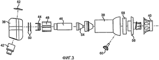
Фиг.3 - корпус видеоэндоскопа в разобранном виде, согласно изобретению,Figure 3 - the housing of the video endoscope disassembled, according to the invention,
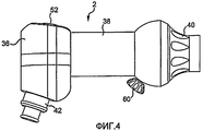
Фиг.4 - корпус видеоэндоскопа в собранном виде, согласно изобретению;Figure 4 - the body of the video endoscope in assembled form, according to the invention;
Фиг.5 - общий вид крепления муфты на чехле, согласно изобретению;5 is a General view of the mounting of the coupling on the cover, according to the invention;
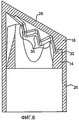
Фиг.6 - вариант выполнения средств рассеяния и ориентации света на конце кожуха на фиг.2, согласно изобретению;6 is an embodiment of the means of scattering and orientation of light at the end of the casing in figure 2, according to the invention;
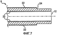
Фиг.7 - частичный продольный разрез жесткой части кожуха, согласно изобретению.7 is a partial longitudinal section of the rigid part of the casing according to the invention.
Описание предпочтительных вариантов воплощения изобретенияDESCRIPTION OF PREFERRED EMBODIMENTS
На Фиг.1 показан общий вид видеоэндоскопа, содержащего вводимую часть, образованную жестким оптическим стержнем (не показан), закрытым защитным кожухом 4. Кожух 4 закреплен на эндоскопе с помощью блокирующего средства 6.Figure 1 shows a General view of the video endoscope containing the input part formed by a rigid optical rod (not shown), closed with a
На Фиг.2 показан более детально защитный кожух 4. Кожух 4 содержит трубчатую цилиндрическую часть 8, которая имеет ближний конец 10 и дистальный конец 12. Со стороны дистального конца защитный кожух 4 содержит рассеивающую вставку 14 и угловую корректирующую линзу 16. Со стороны ближнего конца 10 защитный кожух 4 содержит блокирующую систему 18, держатель муфты 20, а также блокирующее средство 6.Figure 2 shows in more detail the
Трубчатая цилиндрическая часть 8 защитного кожуха 4 более детально показана на фиг.7, где показан продольный разрез дистального конца трубчатой цилиндрической части 8. Сердцевина цилиндрической трубчатой части 8 выполнена, например, из поликарбоната, например, РММА (полиметилметакрилата). Сердцевина, как по внутренней поверхности, так и по внешней поверхности, покрыта слоем 22, выполненным из материала, имеющего коэффициент преломления, меньший, чем коэффициент преломления материала, используемого для изготовления сердцевины цилиндрической трубчатой части 8. Речь идет, например, о фторсодержащем полимере. Слои 22 могут быть экструдированы одновременно с сердцевиной в процессе изготовления трубчатой цилиндрической части 8, либо речь может также идти о нанесении покрытий на и внутри сердцевины трубчатой цилиндрической части 8.The tubular cylindrical part 8 of the
Дистальный конец 12 трубчатой цилиндрической части 8 имеет внешнюю поверхность, содержащую плечо 24, которое предназначено для монтажа угловой корректирующей линзы 16. Рассеивающая вставка 14 установлена внутри угловой корректирующей линзы 16 и между дистальным концом 12 трубчатой цилиндрической части 8 и угловой корректирующей линзой 16. Конструкция, образованная угловой корректирующей линзой 16 и рассеивающей вставкой 14, изображена в увеличенном виде на фиг. 6. Угловая корректирующая линза 16 содержит с одной стороны трубчатую цилиндрическую втулку 26 и с другой стороны конечную часть 28, закрывающую втулку 26.The
Втулка 26 имеет размер, адаптированный к дистальному концу трубчатой цилиндрической части 8. Внутренний диаметр втулки соответствует внешнему диаметру, уменьшенному на плечо 24 цилиндрической трубчатой части 8. Втулка 26 может также упираться в плечо 24.The
Конечная часть 28 угловой корректирующей линзы 16 имеет форму, зависящую от желаемых характеристик и от формы дистального конца, защищаемого оптического стержня. Действительно, в зависимости от варианта использования эндоскопа может быть необходимым иметь освещение аксиальное либо под заданным углом, доходящим до 90°. На чертежах рассматривается вариант освещения под углом 30°. Внешняя поверхность конечной части угловой корректирующей линзы 16 имеет практически плоскую поверхность, имеющую наклон в 30° относительно поперечной плоскости. Угловая корректирующая линза 16 образует крышку, закрывающую дистальный конец 12 трубчатой цилиндрической части 8.The
Угловая корректирующая линза 16 закрывает рассеивающую вставку 14 на дистальном конце защитного кожуха 4. Рассеивающая вставка 14 является трубчатой деталью, предназначенной для рассеивания света, поступающего по трубчатой цилиндрической части 8. Когда рассеивающая вставка 14 размещена на конце защитного кожуха 4, она опирается на дистальный конец цилиндрической трубчатой части 8, а точнее, на сердцевину этой части. Она имеет плоскую кольцевую поверхность, опирающуюся на дистальный конец 12 цилиндрической трубчатой части 8. Противоположный конец рассеивающей вставки 14 выполнен сложной формы, которая зависит от желаемого применения эндоскопа, в частности, от угла освещения, выбранного для ориентации света, исходящего из эндоскопа. Как показано на фиг.6, дистальный конец рассеивающей вставки 14 содержит практически радиальные ребра, которые образуют призму 30. Внутренняя поверхность конечной части 28 угловой корректирующей линзы 16 имеет форму, соответствующую форме дистального конца рассеивающей вставки 14. На фиг.6 показано, что между рассеивающей вставкой 14 и конечной частью 28 угловой корректирующей линзы 16 имеется свободное пространство. Между рассеивающей вставкой 14 и внутренней поверхностью конечной части 28 угловой корректирующей линзы 16 имеется несколько контактных зон. Контактные зоны обеспечивают гарантию хорошего контакта между рассеивающей вставкой 14 и цилиндрической трубчатой частью 8. Они определяют также воздушную линзу 32, которая также участвует в рассеянии и ориентации света.An angular
Блокирующая система 18 у ближнего конца 10 цилиндрической трубчатой части 8 известна специалистам. Речь идет о системе, которая классически имеется в эндоскопе. Обычно эндоскоп направляется и поддерживается направляющей оболочкой (не показана) и блокируется на последней. В качестве системы блокирования 18 в данном случае используется известная специалистам система блокирования. The locking
Более того, системы блокирования, обеспечивающие крепление защитного кожуха 4 на эндоскопе, известны специалистам. Речь идет, например, о таких системах блокирования, которые описаны в ЕР-0456761.Moreover, blocking systems that secure the
Держатель муфты 20 позволяет соединять гибкую муфту 34 с жестким защитным кожухом 4 (фиг.5). Речь идет в данном случае о муфте из гибкого синтетического материала. Муфта имеет длину в несколько метров. Таким образом, перед использованием защитного устройства гибкая муфта 34 складывается. Для облегчения раскрытия муфты над видеоэндоскопом и системой питания муфта предпочтительно складывается телескопически. The holder of the
Фиг.3 изображает рукоятку видеоэндоскопа и основные элементы.Figure 3 depicts the handle of the video endoscope and the main elements.
Корпус 2 (фиг.4) содержит задний корпус 36, передний корпус 38 и передний колпак 40. Питание электричеством и светом осуществляется через вход 42 муфты.The housing 2 (figure 4) contains a
Внутри корпуса 2 (фиг.3) размещен, в частности, приемник 44 изображений, соединенный с объективом 46, содержащим оптические линзы (не показаны). Inside the housing 2 (FIG. 3), in particular, an
Приемник 44 изображений установлен на опоре 48. За приемником 44 изображений находится интегральная печатная плата 50 электронных средств направления и управления видеоэндоскопом. Кнопочное устройство 52, установленное на заднем корпусе 56, служит интерфейсом между печатными платами 50 и пользователем.An
Видеоэндоскоп питается светом от внешнего светового источника через вход 42 муфты. Таким образом, по оптическим волокнам подается свет в видеоэндоскоп. Они распределены в опоре 48 вокруг приемника 44 изображений и объективом 46 и соединены далее с коническим световодом 54 для образования выходного светового кольца, размеры которого соответствуют практически размерам сечения трубчатой цилиндрической части 8 защитного кожуха 4. Трубчатая цилиндрическая вставка (не показана) позволяет направлять свет от выхода светового кольца внутрь корпуса 2 до блокирующих средств 6 таким образом, чтобы передавать свет от внешнего источника света до трубчатой цилиндрической части 8 защитного кожуха 4 с образованием, таким образом, кольцевого светового пучка вокруг ближнего конца жесткого оптического стержня.The video endoscope is powered by light from an external light source through the
Перед корпусом 2 видеоэндоскопа находится соединительная деталь 56, к одной стороне которой присоединен жесткий оптический стержень (не показан), а с другой стороны расположены средства дополнительного крепления блокирующего средства 6 защитного кожуха 4. Что касается переднего колпака 40, то он участвует в креплении жесткого оптического стержня на видеоэндоскопе.In front of the
Между соединительной деталью 56 и передним корпусом 38 корпуса 2 размещен шарикоподшипник 58. Это позволяет поворачивать корпус 2 с приемником 44 изображений относительно жесткого оптического стержня. Блокирующий винт 60 позволяет закреплять корпус 2 в заданном положении.A
Жесткий оптический эндоскоп содержит, предпочтительно, один оптический стержень, размещенный в трубке, например в металлической трубке. Оптический стержень позволяет передавать свет от дистального конца стержня эндоскопа к его входной части и далее на приемник 44 изображений. Внешний диаметр этого стержня эндоскопа (стержень + трубка) составляет около 2 мм (или даже меньше).A rigid optical endoscope preferably contains one optical rod located in a tube, for example in a metal tube. The optical rod allows light to be transmitted from the distal end of the endoscope shaft to its input part and further to the
В конструкции, описанной выше, содержащей эндоскоп и защитное устройство, защитный кожух 4 является активной деталью, которая проводит свет для освещения органа и исследования посредством видеоэндоскопа, и, таким образом, является частью эндоскопа. Объединенные защитный кожух 4 и гибкая муфта 34 служат в данном случае не только для защиты пациента от заражения, но и принимают участие в работе видеоэндоскопа. Хотя в известных эндоскопах вводимая часть эндоскопа, использующая или нет внешний стерильный кожух, служит, с одной стороны, для подвода света к исследуемой зоне, и, с другой стороны, позволяет сфотографировать эту зону, в данном случае жесткий оптический стержень эндоскопа имеет единственную функцию передачи изображения к приемнику 44 изображений. Функцию передачи света к дистальному концу полностью выполняет защитный кожух. Исходя из этого внешний диаметр жесткого оптического стержня может быть уменьшен. Таким образом, можно изготовить эндоскопы диаметром в 2 мм или даже меньше. Защитный кожух 4 защитного устройства согласно изобретению может иметь внешний диаметр около 4 мм. Этот диаметр соответствует внешнему диаметру вводимой части эндоскопа малого диаметра известного уровня техники. Само собой разумеется, что изобретение может быть использовано для других диаметров больших или меньших.In the construction described above, containing an endoscope and a protective device, the
Защитное устройство, в частности его защитный кожух, позволяет обеспечить хорошее направление света. По сравнению с известными эндоскопами можно использовать световой источник меньшей мощности. Описанный выше эндоскоп может работать с лампой в 24 Вт, в то время как лампы известных эндоскопов имеют мощности от 250 до 300 Вт.The protective device, in particular its protective casing, allows for a good direction of light. Compared with known endoscopes, a light source of lower power can be used. The endoscope described above can work with a 24 W lamp, while lamps of known endoscopes have powers from 250 to 300 W.
Адаптируя форму дистальной линзы и объединенной с ней рассеивающей вставки, можно работать с эндоскопом при всех используемых углах наблюдений, например, 0°, 30°, 45°, 70° и 90°.Adapting the shape of the distal lens and the scattering insert combined with it, it is possible to work with the endoscope at all used viewing angles, for example, 0 °, 30 °, 45 °, 70 ° and 90 °.
В эндоскопе согласно настоящему изобретению защитное устройство имеет одноразовое применение. Оно может быть легко надето на жесткий оптический стержень эндоскопа и легко снято. Жесткий оптический стержень можно использовать повторно. Между двумя последовательными исследованиями защитное устройство заменяется, а жесткий оптический стержень при необходимости дезинфицируется с помощью дезинфекционного средства. Таким образом, время иммобилизации эндоскопа между двумя исследованиями весьма уменьшено. In the endoscope according to the present invention, the protective device has a single use. It can be easily put on the rigid optical rod of the endoscope and is easily removed. The rigid optical rod can be reused. Between two consecutive studies, the protective device is replaced, and the rigid optical rod, if necessary, is disinfected with a disinfectant. Thus, the time of immobilization of the endoscope between the two studies is greatly reduced.
По сравнению с известными защитными кожухами защитный кожух 4 имеет большую толщину стенки, чтобы быть проводником света. Эта увеличенная толщина приводит к увеличению жесткости, которая позволяет также повысить безопасность в процессе введения.Compared with the known protective enclosures, the
Из вышесказанного следует, что заявленный эндоскоп проще известных. Стоимость его также может быть уменьшена.From the above it follows that the claimed endoscope is simpler than known. Its cost can also be reduced.
Настоящее изобретение не ограничивается описанным выше в качестве неограничивающего примера варианта осуществления. Оно касается равным образом всех вариантов реализации, доступных специалисту в рамках нижеследующих пунктов формулы изобретения. The present invention is not limited to those described above as a non-limiting example of an embodiment. It applies equally to all embodiments available to the skilled person within the scope of the following claims.
Claims (11)
Applications Claiming Priority (2)
| Application Number | Priority Date | Filing Date | Title |
|---|---|---|---|
| FR06/02887 | 2006-04-03 | ||
| FR0602887A FR2899087B1 (en) | 2006-04-03 | 2006-04-03 | PROTECTION FOR ENDOSCOPE AND CORRESPONDING ENDOSCOPE |
Publications (2)
| Publication Number | Publication Date |
|---|---|
| RU2008143339A RU2008143339A (en) | 2010-05-10 |
| RU2435513C2 true RU2435513C2 (en) | 2011-12-10 |
Family
ID=37648535
Family Applications (1)
| Application Number | Title | Priority Date | Filing Date |
|---|---|---|---|
| RU2008143339/14A RU2435513C2 (en) | 2006-04-03 | 2007-04-03 | Protective device for endoscope and respective endoscope |
Country Status (11)
| Country | Link |
|---|---|
| US (1) | US8454501B2 (en) |
| EP (1) | EP2007270B1 (en) |
| JP (1) | JP5524609B2 (en) |
| CN (1) | CN101466297B (en) |
| AU (1) | AU2007232458B9 (en) |
| BR (1) | BRPI0709453A2 (en) |
| CA (1) | CA2648069C (en) |
| FR (1) | FR2899087B1 (en) |
| MX (1) | MX2008012722A (en) |
| RU (1) | RU2435513C2 (en) |
| WO (1) | WO2007113400A1 (en) |
Cited By (1)
| Publication number | Priority date | Publication date | Assignee | Title |
|---|---|---|---|---|
| RU2741927C2 (en) * | 2016-05-25 | 2021-01-29 | Аватерамедикал Гмбх | System for sterile handling of non-sterile instruments in a sterile environment |
Families Citing this family (14)
| Publication number | Priority date | Publication date | Assignee | Title |
|---|---|---|---|---|
| DE102007026234A1 (en) * | 2007-05-31 | 2008-12-04 | Karl Storz Gmbh & Co. Kg | Videoscope |
| US9050036B2 (en) | 2007-06-19 | 2015-06-09 | Minimally Invasive Devices, Inc. | Device for maintaining visualization with surgical scopes |
| WO2010068265A1 (en) | 2008-12-10 | 2010-06-17 | Minimally Invasive Devices, Llc | Systems and methods for optimizing and maintaining visualization of a surgical field during the use of surgical scopes |
| US9078562B2 (en) | 2010-01-11 | 2015-07-14 | Minimally Invasive Devices, Inc. | Systems and methods for optimizing and maintaining visualization of a surgical field during the use of surgical scopes |
| EP2600759A4 (en) | 2010-08-04 | 2013-08-28 | Minimally Invasive Devices Llc | Systems and methods for optimizing and maintaining visualization of a surgical field during the use of surgical scopes |
| US9522017B2 (en) | 2010-12-03 | 2016-12-20 | Minimally Invasive Devices, Inc. | Devices, systems, and methods for performing endoscopic surgical procedures |
| US8942530B2 (en) | 2011-09-20 | 2015-01-27 | San Marino Capital, Inc. | Endoscope connector method and apparatus |
| EP2659828B1 (en) * | 2011-11-25 | 2015-07-01 | Olympus Medical Systems Corp. | Endoscope |
| FR2987254B1 (en) * | 2012-02-24 | 2015-06-12 | Helgoual Ch Guy L | ENDOSCOPIC DEVICE INTENDED PARTICULARLY FOR MEDICAL USE. |
| US10398292B2 (en) | 2013-03-14 | 2019-09-03 | Floshield, Inc. | Fluid dispensing control systems and methods |
| EP2856926A1 (en) | 2013-10-04 | 2015-04-08 | Tidi Products, LLC | Sheath for a medical or dental instrument |
| USD731652S1 (en) | 2014-02-19 | 2015-06-09 | Tidi Products, Llc | Dental curing light sleeve |
| CN104921692A (en) * | 2015-06-19 | 2015-09-23 | 京东方光科技有限公司 | Peeping assisting device |
| USD989305S1 (en) | 2018-09-28 | 2023-06-13 | Stryker Corporation | Endoscope |
Family Cites Families (21)
| Publication number | Priority date | Publication date | Assignee | Title |
|---|---|---|---|---|
| US216618A (en) * | 1879-06-17 | Improvement in hame-tug loops | ||
| US3801181A (en) * | 1968-08-10 | 1974-04-02 | Nippon Selfoc Co Ltd | Gradient index light conductor |
| DE3574238D1 (en) * | 1985-08-13 | 1989-12-21 | Sumitomo Electric Industries | Method for producing an optical sensor |
| DE58905458D1 (en) * | 1988-11-18 | 1993-10-07 | Effner Biomet Gmbh | Endoscope, especially arthroscope. |
| US4878485A (en) * | 1989-02-03 | 1989-11-07 | Adair Edwin Lloyd | Rigid video endoscope with heat sterilizable sheath |
| US5377047A (en) * | 1992-04-13 | 1994-12-27 | Linvatec Corporation | Disposable endoscope employing positive and negative gradient index of refraction optical materials |
| US5704892A (en) * | 1992-09-01 | 1998-01-06 | Adair; Edwin L. | Endoscope with reusable core and disposable sheath with passageways |
| JPH06209904A (en) * | 1993-01-14 | 1994-08-02 | Olympus Optical Co Ltd | Endoscope |
| JP3872852B2 (en) * | 1996-02-26 | 2007-01-24 | オリンパス株式会社 | Endoscope TV observation system, light source unit used for endoscope TV observation system, and small light source unit for endoscope |
| WO1998035607A1 (en) * | 1997-02-13 | 1998-08-20 | Matsushita Electric Industrial Co., Ltd. | Endoscope, method of manufacturing the same, and inserting member |
| US8024027B2 (en) * | 1998-09-03 | 2011-09-20 | Hyperspectral Imaging, Inc. | Infrared endoscopic balloon probes |
| JP2001166223A (en) * | 1999-12-03 | 2001-06-22 | Olympus Optical Co Ltd | Endoscope |
| JP2001290085A (en) * | 2000-04-05 | 2001-10-19 | Olympus Optical Co Ltd | Endoscope |
| RU2192029C1 (en) | 2001-05-11 | 2002-10-27 | Государственное Унитарное Дочернее Предприятие Государственного Предприятия "Нпо Астрофизика" Особое Конструкторское Бюро "Солнечная И Точная Оптика" | Gradient optical system of superthin endoscope |
| US8038602B2 (en) * | 2001-10-19 | 2011-10-18 | Visionscope Llc | Portable imaging system employing a miniature endoscope |
| US6863651B2 (en) * | 2001-10-19 | 2005-03-08 | Visionscope, Llc | Miniature endoscope with imaging fiber system |
| US7762965B2 (en) * | 2001-12-10 | 2010-07-27 | Candela Corporation | Method and apparatus for vacuum-assisted light-based treatments of the skin |
| AU2002321806A1 (en) * | 2001-12-10 | 2003-06-23 | Inolase 2002 Ltd. | Method and apparatus for improving safety during exposure to a monochromatic light source |
| JP2003325449A (en) * | 2002-05-15 | 2003-11-18 | Fuji Photo Optical Co Ltd | Connection structure for light source connector for endoscope to light source device |
| US20050245789A1 (en) * | 2003-04-01 | 2005-11-03 | Boston Scientific Scimed, Inc. | Fluid manifold for endoscope system |
| US7510524B2 (en) * | 2005-04-04 | 2009-03-31 | Invuity, Inc. | Optical waveguide sheath |
-
2006
- 2006-04-03 FR FR0602887A patent/FR2899087B1/en not_active Expired - Fee Related
-
2007
- 2007-04-03 CA CA2648069A patent/CA2648069C/en active Active
- 2007-04-03 AU AU2007232458A patent/AU2007232458B9/en active Active
- 2007-04-03 JP JP2009503612A patent/JP5524609B2/en active Active
- 2007-04-03 RU RU2008143339/14A patent/RU2435513C2/en active
- 2007-04-03 CN CN2007800190860A patent/CN101466297B/en active Active
- 2007-04-03 EP EP07731242.9A patent/EP2007270B1/en active Active
- 2007-04-03 MX MX2008012722A patent/MX2008012722A/en active IP Right Grant
- 2007-04-03 WO PCT/FR2007/000564 patent/WO2007113400A1/en active Application Filing
- 2007-04-03 BR BRPI0709453-1A patent/BRPI0709453A2/en not_active Application Discontinuation
- 2007-04-03 US US12/295,726 patent/US8454501B2/en active Active
Non-Patent Citations (1)
| Title |
|---|
| ХАЦЕВИЧ Т.Н. и др. Эндоскопы // Уч.пособие. - Новосибирск: СГГА, 2002. * |
Cited By (2)
| Publication number | Priority date | Publication date | Assignee | Title |
|---|---|---|---|---|
| RU2741927C2 (en) * | 2016-05-25 | 2021-01-29 | Аватерамедикал Гмбх | System for sterile handling of non-sterile instruments in a sterile environment |
| US11547282B2 (en) | 2016-05-25 | 2023-01-10 | avateramedical GmBH | Arrangement for the sterile handling of non-sterile units in a sterile environment |
Also Published As
| Publication number | Publication date |
|---|---|
| RU2008143339A (en) | 2010-05-10 |
| WO2007113400A1 (en) | 2007-10-11 |
| AU2007232458A1 (en) | 2007-10-11 |
| US8454501B2 (en) | 2013-06-04 |
| CN101466297B (en) | 2012-12-19 |
| EP2007270A1 (en) | 2008-12-31 |
| MX2008012722A (en) | 2009-04-30 |
| US20090253962A1 (en) | 2009-10-08 |
| AU2007232458B2 (en) | 2013-08-01 |
| FR2899087B1 (en) | 2008-06-20 |
| AU2007232458B9 (en) | 2013-12-19 |
| BRPI0709453A2 (en) | 2011-07-12 |
| JP2009532153A (en) | 2009-09-10 |
| FR2899087A1 (en) | 2007-10-05 |
| CN101466297A (en) | 2009-06-24 |
| JP5524609B2 (en) | 2014-06-18 |
| EP2007270B1 (en) | 2019-08-07 |
| CA2648069A1 (en) | 2007-10-11 |
| CA2648069C (en) | 2015-10-27 |
Similar Documents
| Publication | Publication Date | Title |
|---|---|---|
| RU2435513C2 (en) | Protective device for endoscope and respective endoscope | |
| JP3739592B2 (en) | Laparoscopic device | |
| JP5225438B2 (en) | Small endoscope system | |
| CA2748436C (en) | Miniature endoscope with imaging fiber system | |
| US8317689B1 (en) | Miniature endoscope system | |
| US5688224A (en) | Medical visualization device | |
| JP2009532153A5 (en) | ||
| US20190298161A1 (en) | Device for use in hysteroscopy | |
| JP3486804B2 (en) | Tip structure of insertion section for oblique endoscope | |
| US7991260B2 (en) | Light-diffusing safety cap | |
| JPH09122065A (en) | Endoscope | |
| US20230270322A1 (en) | Endoscope | |
| GB2536869A (en) | Illumination device | |
| GB2606862A (en) | Front-end structure for insertion part of endoscope | |
| WO2010129052A1 (en) | Light diffusing safety cap | |
| GB2339539A (en) | Medical viewing device | |
| JP2018029885A (en) | Electronic scope, electronic scope system, and lens unit | |
| JP2001161628A (en) | Endoscope used with microscopic operation |