RU2434317C2 - Radio-frequency power amplifiers - Google Patents
Radio-frequency power amplifiers Download PDFInfo
- Publication number
- RU2434317C2 RU2434317C2 RU2008147889/09A RU2008147889A RU2434317C2 RU 2434317 C2 RU2434317 C2 RU 2434317C2 RU 2008147889/09 A RU2008147889/09 A RU 2008147889/09A RU 2008147889 A RU2008147889 A RU 2008147889A RU 2434317 C2 RU2434317 C2 RU 2434317C2
- Authority
- RU
- Russia
- Prior art keywords
- amplifier
- control
- power
- signal
- voltage
- Prior art date
Links
Images


Classifications
-
- H—ELECTRICITY
- H03—ELECTRONIC CIRCUITRY
- H03F—AMPLIFIERS
- H03F1/00—Details of amplifiers with only discharge tubes, only semiconductor devices or only unspecified devices as amplifying elements
- H03F1/02—Modifications of amplifiers to raise the efficiency, e.g. gliding Class A stages, use of an auxiliary oscillation
- H03F1/0205—Modifications of amplifiers to raise the efficiency, e.g. gliding Class A stages, use of an auxiliary oscillation in transistor amplifiers
- H03F1/0211—Modifications of amplifiers to raise the efficiency, e.g. gliding Class A stages, use of an auxiliary oscillation in transistor amplifiers with control of the supply voltage or current
- H03F1/0244—Stepped control
-
- H—ELECTRICITY
- H03—ELECTRONIC CIRCUITRY
- H03F—AMPLIFIERS
- H03F1/00—Details of amplifiers with only discharge tubes, only semiconductor devices or only unspecified devices as amplifying elements
- H03F1/02—Modifications of amplifiers to raise the efficiency, e.g. gliding Class A stages, use of an auxiliary oscillation
- H03F1/0205—Modifications of amplifiers to raise the efficiency, e.g. gliding Class A stages, use of an auxiliary oscillation in transistor amplifiers
- H03F1/0211—Modifications of amplifiers to raise the efficiency, e.g. gliding Class A stages, use of an auxiliary oscillation in transistor amplifiers with control of the supply voltage or current
- H03F1/0216—Continuous control
- H03F1/0222—Continuous control by using a signal derived from the input signal
-
- H—ELECTRICITY
- H03—ELECTRONIC CIRCUITRY
- H03F—AMPLIFIERS
- H03F1/00—Details of amplifiers with only discharge tubes, only semiconductor devices or only unspecified devices as amplifying elements
- H03F1/02—Modifications of amplifiers to raise the efficiency, e.g. gliding Class A stages, use of an auxiliary oscillation
- H03F1/0205—Modifications of amplifiers to raise the efficiency, e.g. gliding Class A stages, use of an auxiliary oscillation in transistor amplifiers
- H03F1/0261—Modifications of amplifiers to raise the efficiency, e.g. gliding Class A stages, use of an auxiliary oscillation in transistor amplifiers with control of the polarisation voltage or current, e.g. gliding Class A
- H03F1/0266—Modifications of amplifiers to raise the efficiency, e.g. gliding Class A stages, use of an auxiliary oscillation in transistor amplifiers with control of the polarisation voltage or current, e.g. gliding Class A by using a signal derived from the input signal
-
- H—ELECTRICITY
- H03—ELECTRONIC CIRCUITRY
- H03F—AMPLIFIERS
- H03F1/00—Details of amplifiers with only discharge tubes, only semiconductor devices or only unspecified devices as amplifying elements
- H03F1/32—Modifications of amplifiers to reduce non-linear distortion
-
- H—ELECTRICITY
- H03—ELECTRONIC CIRCUITRY
- H03F—AMPLIFIERS
- H03F3/00—Amplifiers with only discharge tubes or only semiconductor devices as amplifying elements
- H03F3/20—Power amplifiers, e.g. Class B amplifiers, Class C amplifiers
- H03F3/24—Power amplifiers, e.g. Class B amplifiers, Class C amplifiers of transmitter output stages
-
- H—ELECTRICITY
- H03—ELECTRONIC CIRCUITRY
- H03F—AMPLIFIERS
- H03F2200/00—Indexing scheme relating to amplifiers
- H03F2200/105—A non-specified detector of the power of a signal being used in an amplifying circuit
-
- H—ELECTRICITY
- H03—ELECTRONIC CIRCUITRY
- H03F—AMPLIFIERS
- H03F2200/00—Indexing scheme relating to amplifiers
- H03F2200/468—Indexing scheme relating to amplifiers the temperature being sensed
-
- H—ELECTRICITY
- H03—ELECTRONIC CIRCUITRY
- H03F—AMPLIFIERS
- H03F2201/00—Indexing scheme relating to details of amplifiers with only discharge tubes, only semiconductor devices or only unspecified devices as amplifying elements covered by H03F1/00
- H03F2201/32—Indexing scheme relating to modifications of amplifiers to reduce non-linear distortion
- H03F2201/3203—Indexing scheme relating to modifications of amplifiers to reduce non-linear distortion the amplifier comprising means for back off control in order to reduce distortion
Abstract
Description
Настоящее изобретение относится к радиочастотным усилителям мощности.The present invention relates to radio frequency power amplifiers.
Область техники, к которой относится изобретениеFIELD OF THE INVENTION
Общим требованием, особенно для применений искусственных спутников, является то, что каждый элемент многоэлементной антенной решетки, например фазированных решеток, можно возбуждать с помощью соответствующего блока питания и одиночного усилителя мощности. Сигналом усиленной мощности для каждой антенны можно точно управлять по амплитуде и фазе относительно других элементов антенны. Для этой цели обычно используют твердотельные усилители мощности (solid state power amplifiers, SSPAs), но усилители должны удовлетворять строгой линейности, кпд и амплитудно-фазовым следящим характеристикам, требуемым для эксплуатации в активных антенных решетках.A general requirement, especially for artificial satellite applications, is that each element of a multi-element antenna array, such as phased arrays, can be excited using an appropriate power supply and a single power amplifier. The amplified power signal for each antenna can be precisely controlled in amplitude and phase relative to other elements of the antenna. Solid state power amplifiers (SSPAs) are usually used for this purpose, but the amplifiers must satisfy the strict linearity, efficiency, and amplitude-phase tracking characteristics required for operation in active antenna arrays.
Уровень нелинейных искажений, кпд и линейность усилителя можно оптимизировать при заданной выходной радиочастотной мощности путем тщательного подбора условий смещения. Однако, поскольку возбуждение усилителя уменьшено, усилитель сбрасывает мощность, и амплитуда становится менее искаженной, что приводит к падению кпд. Линейность повышается, но во многих случаях это не является применимым требованием. При эксплуатации активных антенных решеток это приводит к тому, что в некоторых или во всех усилителях работа при кпд, меньшем оптимального, зависит от информационных нагрузок и условий наведения луча (которые могут придавать амплитуде, проходящей через решетку, «конусность», когда усилители имеют плавно снижающуюся, проходящую через решетку выходную амплитуду).The level of nonlinear distortion, efficiency and linearity of the amplifier can be optimized for a given output RF power by carefully selecting the bias conditions. However, since the excitation of the amplifier is reduced, the amplifier resets the power, and the amplitude becomes less distorted, which leads to a drop in efficiency. Linearity is increased, but in many cases this is not an applicable requirement. When operating active antenna arrays, this leads to the fact that in some or all amplifiers, operation with an efficiency lower than optimal depends on information loads and beam guidance conditions (which can give the amplitude passing through the array a “taper” when the amplifiers have a smooth decreasing output amplitude passing through the grating).
Во избежание сомнений, термины, используемые выше, имеют следующие значения.For the avoidance of doubt, the terms used above have the following meanings.
Нелинейные искажения: могут быть обозначены, например, как: уменьшение «дифференциального» или «наклонного» усиления, вызванного нелинейностью переходных характеристик усилителя. Нелинейные искажения можно понимать как уровень отклонения от линейного усиления, поскольку у усилителя приближают его характеристики насыщения к максимальному усилению. Nonlinear distortion: can be indicated, for example, as: reduction of the "differential" or "oblique" gain caused by the nonlinearity of the transient characteristics of the amplifier. Nonlinear distortion can be understood as the level of deviation from linear gain, since the saturation characteristics of an amplifier bring it closer to the maximum gain.
Сброс мощности: величина, на которую входная мощность и выходная мощность уменьшаются, в связи с тем что рабочая точка усилителя перемещается вдоль его рабочей характеристики от состояния высокой мощности к состоянию его низкой мощности. Power reset: the amount by which the input power and output power are reduced due to the fact that the operating point of the amplifier moves along its operating characteristic from a state of high power to a state of its low power.
КПД: отношение выходной радиочастотной мощности, предназначенной для передачи, к входной мощности постоянного тока, обеспечиваемой блоком питания. Efficiency: the ratio of the output RF power intended for transmission to the input DC power provided by the power supply.
Линейность: как описано здесь, существуют различные меры линейности, но общей мерой является соотношение взаимной модуляции несущей (соотношение C/l - отношение мощности в целевом канале к мощности «утечки» в соседний канал многоканальной системы). Linearity: as described here, there are various linearity measures, but the common measure is the ratio of the mutual modulation of the carrier (C / l is the ratio of the power in the target channel to the power of the “leakage” to the adjacent channel of the multichannel system).
Автоматическое регулирование смещения усилителя для минимизации падения кпд при сбросе мощности раскрыто для усилителей мощности, разработанных компанией Silicon Bipolar Transistors (Кремниевые биполярные транзисторы) в работе «Последние разработки в технологии твердотельных усилителей мощности и их применимость для мобильных систем космических сегментов третьего поколения», страницы 264-268, Четвертая Международная конференция по спутниковым системам для мобильных систем связи и навигации; октябрь, 1988 г. Такая технология представляет собой аналоговую технологию, включающую в себя регулировку база-эмиттерного напряжения биполярных выходных транзисторов. Такая технология не может быть создана для работы с усилителями, использующими транзисторы с полевым эффектом (Field Effect Transistors, FETs), и поэтому для усилителей она строго ограничена для потокового использования.Automatic amplifier bias control to minimize power drop during power loss is disclosed to power amplifiers developed by Silicon Bipolar Transistors in Recent Developments in Solid State Power Amplifier Technology and its Applicability for Third Generation Space Segment Mobile Systems, page 264 -268, Fourth International Conference on Satellite Systems for Mobile Communications and Navigation; October, 1988. This technology is an analog technology that includes adjusting the base-emitter voltage of bipolar output transistors. This technology cannot be designed to work with amplifiers using Field Effect Transistors (FETs), and therefore for amplifiers it is strictly limited for streaming use.
Другая более сложная известная технология - в особенности усилители Chireix outphasing (LINC) и усилители Догерти. Эти устройства требуют разделения входного сигнала на два параллельных усилительных тракта, с последующим комбинированием усиленных сигналов. Такие технологии сложны для запуска и первоначально предназначены для максимизации кпд при заданном сбросе мощности, когда усилитель демонстрирует очень высокую линейность.Another more sophisticated technology known is Chireix outphasing (LINC) amplifiers and Dougherty amplifiers. These devices require separation of the input signal into two parallel amplification paths, followed by a combination of amplified signals. Such technologies are difficult to start and are originally designed to maximize efficiency at a given power drop when the amplifier exhibits very high linearity.
Ни одна из вышеупомянутых технологий не направлена на выполнение требований, касающихся усилителей, функционирующих в современной активной решетке антенн. Основное необходимое условие для таких усилителей состоит в том, что они должны отслеживать друг друга по коэффициенту усиления и фазе передачи, а во многих случаях усилители функционируют при различных уровнях возбуждения и температурах.None of the above technologies is aimed at fulfilling the requirements for amplifiers operating in a modern active antenna array. The main necessary condition for such amplifiers is that they must track each other in terms of gain and phase of transmission, and in many cases the amplifiers operate at different excitation levels and temperatures.
В работе «Решения для полосового усилителя мощности для космического сегмента ИНМАРСАТ (International Maritime Satellite Organization Международная организация морской спутниковой связи, ИНМАРСАТ)», семинар IEE по микроволновым и радиочастотным усилителям мощности, 7 декабря, 2000 г., Д. Сеймур, страницы 6/1-6/6, раскрыта система для регулирования твердотельного усилителя мощности (solid state power amplifier, SSPA) по коэффициенту усиления, крутизне амплитудно-частотной характеристики и фазе, таким образом, чтобы эти характеристики оставались строго постоянными, и чтобы они отслеживались относительно других SSPA решетки, с большим количеством SSPA. Система включает в себя электронный стабилизатор напряжения (Electronic Power Conditioner, EPC), который представляет собой блок питания, адаптированный для использования в космических приложениях. Управление ASIC (applications specific integrated circuit, специализированная интегральная схема) принимает сигнал температуры усилителя и входной питающий сигнал усилителя и получает доступ к цифровым компенсационным данным, содержащимся в (electrically erasable programmable read-only memory, электрически стираемое программируемое постоянное запоминиющее устройство) для обеспечения, в зависимости от получаемых сигналов, соответствующих аналоговых управляющих сигналов, для управления коэффициентом усиления, крутизной амплитудно-частотной характеристики и фазой усилителя.In the work “Solutions for a band power amplifier for the space segment INMARSAT (International Maritime Satellite Organization, INMARSAT)”, IEE Workshop on Microwave and Radio Frequency Power Amplifiers, December 7, 2000, D. Seymour,
СУЩНОСТЬ ИЗОБРЕТЕНИЯSUMMARY OF THE INVENTION
Задачей EEPROM настоящего изобретения является обеспечение системы усилителя, которая может значительно улучшить характеристики усилителя во всем динамическом диапазоне.The objective of the EEPROM of the present invention is to provide an amplifier system that can significantly improve amplifier performance over the entire dynamic range.
Согласно своей первой особенности изобретение обеспечивает систему усилителя для питания электроэнергией элемента антенны, причем система усилителя содержит:According to its first feature, the invention provides an amplifier system for powering an antenna element, the amplifier system comprising:
средство радиочастотного усилителя, имеющее канал, усиливающий сигнал, который включает в себя, по меньшей мере, силовой выходной каскад;RF amplifier means having a signal amplifying channel that includes at least a power output stage;
средство источника питания электроэнергией, для обеспечения переменного значения напряжения постоянного тока для электропитания, по меньшей мере, упомянутого силового выходного каскада упомянутого средства радиочастотного усилителя;means for supplying electric energy to provide an alternating DC voltage value for supplying at least said power output stage of said RF amplifier means;
средство управления для приема в качестве управляющего входного сигнала входной мощности от упомянутого средства радиочастотного усилителя, для обеспечения, в ответ на управляющий входной сигнал, сигнала управления напряжением для упомянутого средства источника электропитания, для определения значения упомянутого напряжения постоянного тока;control means for receiving, as a control input signal, input power from said RF amplifier means, for providing, in response to a control input signal, a voltage control signal for said power supply means for determining a value of said DC voltage;
и упомянутое средство управления, установленное таким образом, чтобы значение упомянутого напряжения постоянного тока для упомянутого силового выходного каскада изменялось так, чтобы управлять нелинейными искажениями упомянутого средства радиочастотного усилителя для изменения значений упомянутой входной мощности, пригодное для регулирования, по меньшей мере, одной из характеристик: линейности усилителя, кпд усилителя и теплового рассеивания упомянутого средства радиочастотного усилителя.and said control means, set so that the value of said DC voltage for said power output stage is varied so as to control non-linear distortions of said means of a radio frequency amplifier for changing values of said input power, suitable for controlling at least one of the characteristics: the linearity of the amplifier, the efficiency of the amplifier, and thermal dissipation of said means of the radio frequency amplifier.
Согласно своей второй особенности изобретение обеспечивает систему усилителя для электропитания элемента антенны, причем система усилителя содержит:According to its second aspect, the invention provides an amplifier system for powering an antenna element, the amplifier system comprising:
средство радиочастотного усилителя, имеющее канал, усиливающий сигнал, который включает в себя, по меньшей мере, силовой выходной каскад;RF amplifier means having a signal amplifying channel that includes at least a power output stage;
средство источника электропитания для обеспечения изменяемого значения напряжения постоянного тока для электропитания, по меньшей мере, упомянутого силового выходного каскада упомянутого средства радиочастотного усилителя;power supply means for providing a variable DC voltage value for powering at least said power output stage of said RF amplifier means;
средство управления для приема в качестве управляющего входного сигнала сигнала входной мощности от упомянутого средства радиочастотного усилителя, для обеспечения, в ответ на управляющий входной сигнал, сигнала управления напряжением для упомянутого средства источника питания, для определения значения упомянутого напряжения постоянного тока;control means for receiving, as a control input signal, an input power signal from said RF amplifier means, for providing, in response to a control input signal, a voltage control signal for said power source means for determining a value of said DC voltage;
и упомянутое средство управления, включающее в себя средство хранения, которое содержит набор управляющих слов, которые задают выходные значения упомянутого сигнала управления напряжением для изменения значений упомянутой входной мощности, посредством которого изменяют значение упомянутого напряжения постоянного тока, и посредством которого управляют заданным параметром упомянутого средства радиочастотного усилителя.and said control means including storage means that comprises a set of control words that specify the output values of said voltage control signal for changing values of said input power, by means of which the value of said DC voltage is changed, and by which a predetermined parameter of said radio frequency means is controlled amplifier.
Система усилителя в соответствии с изобретением может питать одноэлементную антенну для космической, воздушной или наземно базируемой передачи. Однако система усилителя адаптирована конкретно для возбуждения соответствующего элемента многоэлементной антенны или антенной решетки для космического корабля. Таким образом, обеспечено множество таких усилительных систем, возбуждающих соответствующие элементы антенны, например удобно размещенные в виде матричного усилителя мощности (Matrix Power Amplifier, MPA). Предпочтительно, чтобы усилительная система представляла собой твердотельный усилитель мощности (solid state power amplifiers, SSPA), адаптированный для космических применений, который включает в себя радиочастотный усилитель, электронный стабилизатор напряжения и секцию управления. Секция управления может быть выполнена на той же монтажной плате или интегрирована с компонентами радиочастотного усилителя. Радиочастотный усилитель имеет усиливающий канал, обычно включающий в себя предварительный усилитель, усилитель-формирователь и усилитель мощности или силовой выходной каскад. По желанию, силовой выходной каскад может содержать множество усилительных блоков, установленных в последовательной/параллельной решетке.The amplifier system in accordance with the invention can power a single-element antenna for space, air or ground based transmission. However, the amplifier system is specifically adapted to excite the corresponding element of a multi-element antenna or antenna array for a spacecraft. Thus, a plurality of such amplification systems are provided that drive the corresponding antenna elements, for example, conveniently arranged as a Matrix Power Amplifier (MPA). Preferably, the amplification system is a solid state power amplifiers (SSPA) adapted for space applications, which includes a radio frequency amplifier, an electronic voltage regulator and a control section. The control section can be performed on the same circuit board or integrated with components of an RF amplifier. An RF amplifier has an amplification channel, typically including a preamplifier, a driver amplifier, and a power amplifier or power output stage. Optionally, the power output stage may comprise a plurality of amplifier units installed in a series / parallel array.
Силовой выходной каскад может включать в себя один или несколько силовых транзисторов. В соответствии с предпочтительным вариантом современной технологии, силовые транзисторы представляют собой полевые транзисторы (field-effect transistor, FETs), но они могут быть и биполярными транзисторами, или транзисторами, которые еще не имеют общего промышленного применения. Существуют различные типы транзисторов, все рассматриваемые как FET, например HFET (Heterojunction Field-Effect Transistor, полевой транзистор с управляющим гетеропереходом), PHEMT (Pseudomorphic High Electron Mobility Transistor, транзистор с высокой подвижностью электронов). Силовые транзисторы могут быть изготовлены из высококачественного GaAs или GaN, или из других материалов, таких как Si, SiGe, SiC, алмаз, пластмассы. Не исключены и термоионные устройства, такие как TWTA (traveling-wave-tube amplifier, усилитель на лампе бегущей волны).The power output stage may include one or more power transistors. In accordance with the preferred embodiment of modern technology, power transistors are field-effect transistors (FETs), but they can be bipolar transistors, or transistors that do not yet have common industrial applications. There are various types of transistors, all considered to be FETs, for example, HFET (Heterojunction Field-Effect Transistor, Field Transistor with Control Heterogeneous Junction), PHEMT (Pseudomorphic High Electron Mobility Transistor, Transistor with High Electron Mobility). Power transistors can be made of high quality GaAs or GaN, or other materials such as Si, SiGe, SiC, diamond, plastics. Thermionic devices such as TWTA (traveling-wave-tube amplifier, traveling-wave tube amplifier) are not excluded.
Средство источника электропитания для системы усилителя может содержать электронный стабилизатор напряжения (Electronic Power Conditioner, EPC), который адаптирован для использования в космических применениях, и принимает питание от шины питания космического корабля, и обеспечивает управляемое напряжение питания постоянного тока (основное вторичное напряжение) для питания средства радиочастотного усилителя и средства управления. Для усилителей с FET транзисторами напряжение постоянного тока представляет собой напряжение стока FET транзистора. В соответствии с изобретением величину напряжения питания постоянного тока, подаваемого на выходной каскад радиочастотного усилителя, регулируют в зависимости от управляющего входного сигнала, подаваемого на блок питания со средства управления. Предпочтительно, величину напряжения питания постоянного тока, подаваемого на предконечный каскад радиочастотного усилителя, регулируют аналогичным образом.The power source means for the amplifier system may include an Electronic Power Conditioner (EPC), which is adapted for use in space applications, and receives power from the spacecraft's power bus, and provides a controlled DC voltage (primary secondary voltage) for powering RF amplifier means and controls. For amplifiers with FETs, the DC voltage is the drain voltage of the FETs. In accordance with the invention, the magnitude of the DC voltage supplied to the output stage of the radio frequency amplifier is controlled depending on the control input signal supplied to the power supply from the control means. Preferably, the magnitude of the DC voltage supplied to the pre-end stage of the RF amplifier is controlled in a similar manner.
Средство управления, при использовании SSPA, может представлять собой интегральные схемы, установленные на тех же монтажных платах, что и радиочастотный усилитель; в качестве альтернативы его можно сформировать отдельно от усилителя. Такое средство управления принимает управляющие входные сигналы с усилителя, главным образом, сигнал входной мощности и сигнал температуры, и обеспечивает управляющие выходные сигналы для управления выбранными параметрами усилителя, например коэффициентом усиления, фазой передачи и крутизны амплитудно-частотной характеристики (за счет регулирования характеристик предусилителя). В соответствии с изобретением средство управления обеспечивает управляющий выходной сигнал для средства источника питания для изменения напряжения питания постоянного тока, подаваемого на выходной силовой каскад усилителя мощности, для управления выбранными параметрами усилителя. Основными параметрами для управления являются линейность и кпд. Однако можно управлять и другими параметрами, например тепловым рассеянием. Как указано выше, важной единицей измерения линейности является соотношение C/l, однако можно использовать и другие единицы измерения, такие как коэффициент мощности шума (Noise Power Ratio, NPR) или коэффициент мощности соседнего канала (Adjacent Channel Power Ratio, ACPR). Соотношение C/l обычно используют для систем с несколькими несущими, но ACPR можно использовать для систем с одной несущей, где можно определить мощность в боковых лепестках единственной несущей, относительно мощности в главном лепестке.The management tool, when using SSPA, can be integrated circuits installed on the same circuit boards as the RF amplifier; alternatively, it can be formed separately from the amplifier. Such a control means receives the control input signals from the amplifier, mainly the input power signal and the temperature signal, and provides control output signals to control the selected parameters of the amplifier, for example, the gain, the transmission phase, and the slope of the amplitude-frequency characteristic (by controlling the characteristics of the preamplifier) . In accordance with the invention, the control means provides a control output signal for the power source means for changing the DC voltage supplied to the output power stage of the power amplifier to control the selected parameters of the amplifier. The main parameters for control are linearity and efficiency. However, other parameters can also be controlled, for example, thermal scattering. As stated above, the C / l ratio is an important unit of linearity, but other units of measure, such as Noise Power Ratio (NPR) or Adjacent Channel Power Ratio (ACPR), can also be used. The C / l ratio is typically used for multi-carrier systems, but ACPR can be used for single-carrier systems where the power in the side lobes of a single carrier can be determined relative to the power in the main lobe.
Желаемый способ управления состоит в поддержании постоянной линейности (интермодуляционное соотношение несущей (C/l)), или линейности, находящейся в желаемых пределах, при поддержании кпд в приемлемых пределах, для изменения значений входного сигнала усилителя, выше желаемого диапазона значений радиочастотного выходного сигнала. В качестве альтернативы, тепловое рассеяние или кпд можно поддерживать постоянным. Для этой цели в изобретении регулируют нелинейные искажения, для изменения уровней входной мощности, путем изменения питающего напряжения постоянного тока, подаваемого на силовой выходной каскад радиочастотного усилителя.The desired control method is to maintain a constant linearity (intermodulation carrier ratio (C / l)), or linearity within the desired limits, while maintaining the efficiency within acceptable limits, to change the values of the input signal of the amplifier above the desired range of values of the radio frequency output signal. Alternatively, heat dissipation or efficiency can be kept constant. For this purpose, the invention controls the non-linear distortion to change the input power levels by changing the DC supply voltage supplied to the power output stage of the RF amplifier.
Это может быть возможным для управления обеспечением вышеописанного способа управления, по меньшей мере, частично с помощью цифровых и аналоговых схем и телеуправляемых сигналов. Схемы средства управления можно обеспечить в любой удобной форме, например в форме ASIC, которые были приняты подходящими. В соответствии с изобретением является предпочтительным, чтобы был предусмотрен EEPROM или другое долговременное средство хранения, в котором содержатся данные, в форме массива управляющих слов, которые задают управляющие выходные значения для достижения желаемых состояний выходного сигнала усилителя. Таким образом, если желательным является поддержание линейности постоянной в желательном диапазоне для изменения значений радиочастотной входной мощности, управляющие слова будут содержать массив соответствующих питающих напряжений постоянного тока для изменения радиочастотной входной мощности. Если предусмотрены другие входные сигналы, такие как температура, и другие выходные сигналы, такие как радиочастотная выходная мощность и фаза, то размеры массива и количество секций управляющих слов будут соответствующим образом повышаться.This may be possible to control the provision of the above control method, at least in part, using digital and analog circuits and telecontrol signals. Control circuitry can be provided in any convenient form, for example in the form of ASICs, which have been adopted as appropriate. In accordance with the invention, it is preferred that an EEPROM or other long-term storage medium is provided that contains data in the form of an array of control words that specify the control output values to achieve the desired states of the amplifier output signal. Thus, if it is desirable to keep the linearity constant in the desired range for changing the values of the radio frequency input power, the control words will contain an array of the corresponding DC supply voltages for changing the radio frequency input power. If other input signals are provided, such as temperature, and other output signals, such as radio frequency output power and phase, then the array size and the number of sections of control words will increase accordingly.
Для обеспечения управляющих слов осуществляют исходный процесс характеризации системы усилителя, при котором желаемый параметр усилителя, такой как линейность, подвергается цифровому управлению посредством испытательного оборудования, до постоянного значения, при изменении входной мощности, при выполнении всего набора технических требований. Питающее напряжение постоянного тока подвергают цифровому управлению для поддержания нелинейных искажений выходного каскада усилителя в требуемых значениях для поддержания линейности постоянной. Записанные управляющие слова отображают соответствующие значения питающего напряжения постоянного тока для значений входной мощности. Ограниченный комплект управляющих слов можно хранить (важнейшие точки), а процесс интерполяции можно осуществлять для определения управляющих слов для промежуточных значений входных/выходных сигналов.To provide control words, the initial characterization process of the amplifier system is carried out, in which the desired amplifier parameter, such as linearity, is digitally controlled by the test equipment, to a constant value, when the input power changes, while fulfilling the whole set of technical requirements. The DC supply voltage is digitally controlled to maintain non-linear distortion of the amplifier output stage at the required values to maintain linear linearity. The recorded control words display the corresponding DC supply voltage values for the input power values. A limited set of control words can be stored (critical points), and the interpolation process can be carried out to determine control words for intermediate values of input / output signals.
Таким образом, настоящее изобретение, по меньшей мере, в своей предпочтительной форме отображает встроенную бортовую автономную и/или телеуправляемую технологию управления, в которой посредством смешанной аналоговой и цифровой электронной схемы, соединенной с электронной памятью, которая содержит данные (полученные из наземных испытаний),Thus, the present invention, at least in its preferred form, displays an integrated on-board autonomous and / or remote-controlled control technology in which, by means of a mixed analog and digital electronic circuitry connected to an electronic memory that contains data (obtained from ground tests),
• линейность и• linearity and
• кпд суммарной мощности, вместе с любым или всеми параметрами:• total power efficiency, together with any or all parameters:
• коэффициент усиления,• gain,
• относительный коэффициент усиления частотной характеристики,• relative gain of the frequency response,
• фазы передачи твердотельного усилителя мощности.• Transmission phases of a solid state power amplifier.
одновременно автоматически поддерживаются на постоянных уровнях (или на близких к постоянным уровням) и находятся выше заданных пороговых значений, тогда как усилитель возбуждают при широком диапазоне уровней выходной мощности, и подвергаются температурным изменениям.at the same time, they are automatically maintained at constant levels (or close to constant levels) and are above predetermined threshold values, while the amplifier is excited at a wide range of output power levels and undergoes temperature changes.
Изобретение может содержать встроенную бортовую технологию управления, в которой посредством управления степенью нелинейных искажений усилителя может проявляться значительное повышение кпд усилителя при широком диапазоне уровней выходной мощности. Возможность сделать это нашло различные воплощения в различных типах усилителя и его применений, а функциональная возможность изобретения может быть расширена до одновременного управления другими параметрами усилителя, если потребуется. При использовании на космических кораблях на уровне полезной нагрузки изобретение является фактором, способствующим получению высокоэффективных активных антенных решеток для гибкого обзора поверхности Земли, и дает возможность для исключения дорогостоящей и работающей с большими потерями сети Output Networks.The invention may include integrated on-board control technology in which, by controlling the degree of non-linear distortion of the amplifier, a significant increase in the efficiency of the amplifier can occur with a wide range of output power levels. The ability to do this has found various incarnations in various types of amplifier and its applications, and the functionality of the invention can be expanded to simultaneously control other parameters of the amplifier, if necessary. When used on spaceships at the payload level, the invention is a factor contributing to the production of highly efficient active antenna arrays for a flexible view of the Earth’s surface, and makes it possible to eliminate the costly and lossy Network Output Networks.
Изобретение обеспечивает уникальную степень гибкости усилителя, поскольку существует потенциально проблематичное взаимодействие с коэффициентом усиления усилителя, которое в любом реальном применении может быть неприемлемым, и ее достижение аналоговыми средствами может быть крайне сложным/нецелесообразным. Это дополнительно подчеркивается при принятии во внимание типичных требований для эксплуатации при верхних значениях температуры.The invention provides a unique degree of flexibility of the amplifier, since there is a potentially problematic interaction with the gain of the amplifier, which in any real application may be unacceptable, and its achievement by analog means can be extremely difficult / impractical. This is further emphasized when taking into account typical requirements for operation at higher temperatures.
Согласно альтернативному варианту воплощения изобретения управление нелинейными искажениями усилителя и кпд осуществляют через телеуправление. В данном случае усилитель может демонстрировать требуемые нелинейные искажения и кпд, но только при дискретных, телеуправляемых установочных параметрах выходной мощности.According to an alternative embodiment of the invention, the control of the non-linear distortion of the amplifier and the efficiency is carried out via telecontrol. In this case, the amplifier can demonstrate the required nonlinear distortion and efficiency, but only with discrete, remote-controlled output power settings.
Краткое описание чертежейBrief Description of the Drawings
Предпочтительные варианты воплощения изобретения далее будут описаны со ссылкой на прилагаемые чертежи, в которых:Preferred embodiments of the invention will now be described with reference to the accompanying drawings, in which:
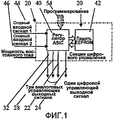
Фиг.1 представляет собой принципиальную схему примерного средства управления, используемого в предпочтительных вариантах воплощения изобретения;Figure 1 is a schematic diagram of an exemplary control used in preferred embodiments of the invention;
Фиг.2 представляет собой схематическую блок-схему первого предпочтительного варианта воплощения изобретения;Figure 2 is a schematic block diagram of a first preferred embodiment of the invention;
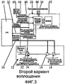
Фиг.3 представляет собой схематическую блок-схему второго предпочтительного варианта воплощения изобретения;Figure 3 is a schematic block diagram of a second preferred embodiment of the invention;
Фиг.4 представляет собой график, иллюстрирующий рабочие характеристики SSPA согласно известному уровню техники;4 is a graph illustrating the performance of SSPAs according to the prior art;
Фиг.5 представляет собой график, иллюстрирующий рабочие характеристики, ожидаемые в соответствии с настоящим изобретением;5 is a graph illustrating the performance expected in accordance with the present invention;
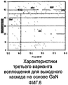
Фиг.6 представляет собой график, иллюстрирующий рабочие характеристики, ожидаемые в соответствии с настоящим изобретением для системы с несколькими несущими, в которой использованы силовые транзисторы на основе GaN в выходном каскаде;6 is a graph illustrating the performance expected in accordance with the present invention for a multi-carrier system that uses GaN-based power transistors in an output stage;
Фиг.7 представляет собой график, иллюстрирующий рабочие характеристики, ожидаемые в соответствии с настоящим изобретением для системы с одной несущей, в которой использованы силовые транзисторы на основе GaN в выходном каскаде;7 is a graph illustrating the performance expected in accordance with the present invention for a single-carrier system that utilizes GaN-based power transistors in an output stage;
Фиг.8 представляет собой схематическую блок-схему третьего предпочтительного варианта воплощения изобретения;FIG. 8 is a schematic block diagram of a third preferred embodiment of the invention; FIG.
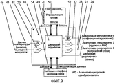
Фиг.9 представляет собой более подробное изображение средства управления согласно Фиг.1; иFig.9 is a more detailed image of the control according to Fig.1; and
Фиг.10 представляет собой концептуальную блок-схему системы усилителя согласно настоящему изобретению, в качестве примера которого приведен SSPA.10 is a conceptual block diagram of an amplifier system according to the present invention, an example of which is SSPA.
Описание предпочтительного варианта воплощенияDescription of the preferred embodiment
Рассмотрим сначала Фиг.10, где система усилителя согласно изобретению в одной примерной форме внедрена в виде твердотельного усилителя мощности (solid state power amplifier, SSPA), в котором секция источника питания содержит электронный стабилизатор напряжения (Electronic Power Conditioner, EPC) 10, причем секция 12 радиочастотного усилителя имеет канал усиления, включающий в себя предварительный усилитель 14, усилитель-формирователь 16 (предконечный каскад усилителя мощности) и усилитель мощности 18 (выходной каскад). Секция управления содержит цифровую 20 схему управления (digital control scheme, DCS), которая обеспечивает управляющими выходными сигналами предварительный 14 усилитель, и EPC 10. В частности, DCS 20 обеспечивает аналоговый управляющий сигнал по линии 22 в EPC 10, цифровой сигнал по линии 24 на фазовое управление 26 в предварительном усилителе 14 (в качестве альтернативы можно использовать аналоговое фазовое управление), аналоговый управляющий сигнал по линии 28 на управление 30 крутизной амплитудно-частотной характеристики и аналоговый управляющий сигнал по линии 32 на управление 34 коэффициентом усиления в предварительном усилителе 14. EPC 10 обеспечивает изменяемое напряжение 36 источника электропитания постоянного тока (напряжения стока или напряжения стока источника) на выходной каскад 18 и предконечный каскад 16 усилителя мощности.Consider first Figure 10, where the amplifier system according to the invention in one exemplary form is implemented as a solid state power amplifier (SSPA), in which the power supply section contains an electronic voltage stabilizer (Electronic Power Conditioner, EPC) 10, and the section The
Обратимся к Фиг.1 и 9, где DCS 20 состоит из смешанного управления аналогово-цифровых сигналов ASIC 40 и электронного стираемого постоянного запоминающего устройства 42 (Electronically Erasable Read Only Memory, EEPROM). Управление ASIC имеет два аналоговых входных порта 44, 46 опорных сигналов и три аналоговых (22, 28, 32) плюс один последовательный цифровой (24) выходных портов управления, доступных для пользователя. Как правило, входные опорные сигналы 44, 46 (обычно температура и входная мощность усилителя) оцифровываются в аналогово-цифровых преобразователях 48 и управляют блоком 49 цифровой обработки управления ASIC, считывающего значащие управляющие слова, хранящиеся в EEPROM. Управляющие слова 50 можно удобно хранить в матричной форме, показанной схематически в виде рядов для входной мощности и столбцов для входной температуры. Доступные управляющие слова затем обрабатываются посредством ASIC и оцифровываются в цифроаналоговых преобразователях 52 для обеспечения управляющих сигналов в его выходных портах 22-32. Управление ASIC 40 имеет программируемый интерфейс I2C 54 (могут быть использованы и другие стандартные интерфейсы), в результате чего может запрашиваться EEPROM, загруженная и считываемая в ходе запуска усилителя или процесса характеризации.Referring to Figs. 1 and 9, where the
Для всех вариантов воплощения, описанных в настоящем документе, принцип работы DCS 20 состоит в том, что усилитель, как часть процесса обработки, «охарактеризован» по всему диапазону его технических требований, особенно по диапазону входной мощности и температуры. В ходе данного процесса характеризации требуемые параметры управляются посредством программного обеспечения и испытательного оборудования, сопряженного с DCS, посредством цифровой настройки до желаемых значений, и, затем, полученные цифровые «управляющие слова» записывают. Таким образом, набирают массив цифровых управляющих слов 50 или «важнейших точек». Программное обеспечение может интерполировать между важнейшими точками для составления полного «скорректированного массива», который загружают в EEPROM 42. В качестве альтернативы в EEPROM 42 хранятся только важнейшие точки, с интерполяцией, выполняемой в реальном времени посредством ASIC 40. В обеих схемах результат состоит в том, что используются данные EEPROM, посредством схем в ASIC, для приведения в действие корректирующих элементов, включенных в конструкцию усилителя для достижения требуемой характеристики.For all the embodiments described herein, the principle of operation of the
Фиг.2 иллюстрирует первый вариант воплощения изобретения, с частями, подобными частям на Фиг.1, 9 и 10 и обозначенными одинаковыми номерами ссылок (также как и для всех последующих фигур). В данном случае на DCS 20 подают одиночный входной опорный сигнал 46 от радиочастотного усилителя 12, напряжение которого связано с его входной мощностью. Используют только один из аналоговых выходных сигналов 22 DCS, и он сопряжен с EPC 10 для управления подачей основного напряжения 36 на управляющий 16 и выходной 18 сток полевых транзисторов FET. В ходе процесса характеризации усилитель используют по всему его динамическому диапазону входной мощности и, посредством вышеупомянутого программного обеспечения и испытательного оборудования, осуществляют цифровое управление основным напряжением 36 EPC для поддержания предконечного и выходного каскадов 16, 18 радиочастотного усилителя при требуемой нелинейности искажений, в целях поддержания постоянного соотношения C/l.FIG. 2 illustrates a first embodiment of the invention, with parts similar to those in FIGS. 1, 9 and 10 and denoted by the same reference numbers (as well as for all subsequent figures). In this case, a single
Вариант воплощения согласно Фиг.2 представляет собой минимальную конфигурацию. На практике, коэффициент усиления усилителя может изменяться регулированием подачи питания стока на возбуждение и выход FET-транзистора, а также могут возникнуть температурные эффекты, с которыми возможно придется иметь дело. Поэтому второй вариант воплощения, показанный на Фиг.3, иллюстрирует конфигурацию изобретения, которое имеет большее практическое применение, где также используют DCS 20 для поддержания полного коэффициента усиления усилителя на постоянном уровне на всем рабочем динамическом диапазоне и температурном диапазоне. Второй опорный входной сигнал 44 подают на DCS 22 от температурного 60 датчика, выполненного на плате усилителя, а второй аналоговый выходной сигнал 32 используют для возбуждения регулируемого аттенюатора 34 (или другого цифрового или аналогового устройства с переменным коэффициентом усиления/ослабления) в радиочастотной цепи. В ходе процесса характеризации усилитель используют по всему динамическому диапазону его входной мощности и по всему диапазону рабочих температур. Таким образом, данные набираются не только для настройки нелинейных искажений с помощью возбуждающего входного сигнала, а также для исключения любых нежелательных изменений нелинейных искажений и абсолютного коэффициента усиления с температурой.The embodiment of FIG. 2 is a minimum configuration. In practice, the gain of the amplifier can be varied by adjusting the supply of drain power to the excitation and output of the FET transistor, and temperature effects can occur that you may have to deal with. Therefore, the second embodiment shown in FIG. 3 illustrates a configuration of the invention, which has a larger practical application, where
Сравнение между собой характеристик усилителя со смещением фиксированного класса A/B, оптимизированного для конкретной требуемой выходной мощности, и характеристик, предполагаемых согласно настоящему изобретению, приведено на Фиг.4 и 5. В усилителе использованы управляющий и выходной FET-транзисторы на основе GaAs, и он включает в себя секцию предварительного усилителя для повышения коэффициента усиления. Фиг.4 иллюстрирует случай фиксированного смещения, где условия смещения, в частности источник напряжения стока, в данном случае были отрегулированы и зафиксированы для достижения оптимальных характеристик в обычной рабочей точке (normal operating point, NOP), составляющей в данном случае чуть менее 12,0 дБ·Вт. Можно видеть, что максимальный кпд в 31% достигается при соотношении трехтональной несущей к интермодуляции (C/l), равном 20 дБ; это значение является типичной добротностью для мобильного усилителя мощности. Однако, поскольку усилитель сбрасывает мощность, кпд падает достаточно быстро, возникает повышение C/l, но это обычно не является техническим требованием системы. Поскольку данный усилитель снабжен DCS, спроектированной для управления полным коэффициентом усиления усилителя в динамическом диапазоне, то факт, что усилитель имеет нелинейные искажения в 2дБ, остается нераскрытым.A comparison of the characteristics of the amplifier with a fixed class A / B bias optimized for the specific required output power and the characteristics assumed according to the present invention is shown in FIGS. 4 and 5. The amplifier uses GaAs control and output FETs, and It includes a pre-amplifier section to increase the gain. Figure 4 illustrates the case of a fixed bias, where the bias conditions, in particular the drain voltage source, in this case were adjusted and fixed to achieve optimal performance at a normal operating point (NOP), which in this case is slightly less than 12.0 dBW You can see that the maximum efficiency of 31% is achieved when the ratio of the three-tone carrier to intermodulation (C / l) is 20 dB; this value is a typical figure of merit for a mobile power amplifier. However, since the amplifier resets power, the efficiency drops quickly enough, an increase in C / l occurs, but this is usually not a technical requirement of the system. Since this amplifier is equipped with a DCS designed to control the full gain of the amplifier in the dynamic range, the fact that the amplifier has 2dB non-linear distortion remains unresolved.
Фиг.5 иллюстрирует улучшение характеристик того же усилителя, включенного в вариант воплощения согласно Фиг.3. В данном случае функция DCS 20 расширена до автоматического поддержания соотношения C/l усилителя на уровне 20 дБ на всем динамическом диапазоне выходной мощности, находящемся чуть выше 3 дБ. Управление нелинейными искажениями скрыто в DCS, также управляющей полным коэффициентом усиления усилителя. Из Фиг.5 непосредственно видно, что, хотя максимальный кпд не больше кпд для случаев фиксированного смещения, кпд при сбросе мощности сильно повышен, а точнее более 30% в диапазоне выходной мощности 10,5-22 Вт. Динамический диапазон, выше которого данные характеристики могут быть достигнуты, зависит от минимальной допустимой линейности (C/l), требуемой, но, в конечном счете, ограниченной пределами допустимого напряжения для управляющего и выходного FET-транзистора.FIG. 5 illustrates an improvement in performance of the same amplifier included in the embodiment of FIG. 3. In this case, the
Следует отметить, что изобретение в равной мере можно применить для достижения постоянного кпд или даже постоянной характеристики рассеяния во всем заданном динамическом диапазоне.It should be noted that the invention can equally be applied to achieve a constant efficiency or even a constant scattering characteristic in the entire given dynamic range.
Настоящее изобретение можно применить к FET-транзиторам, в которых соединена технология широкополосного промежутка на основе нитрида галлия (GaN), а благодаря более высокому диапазону напряжения стока, допускаемому при использовании этих компонентов, можно получить намного более широкие динамические диапазоны.The present invention can be applied to FETs in which gallium nitride (GaN) -based gap technology is connected, and due to the higher drain voltage range allowed by using these components, much wider dynamic ranges can be obtained.
Фиг.6 иллюстрирует ожидаемые характеристики единичного выходного каскада на основе GaN в режиме работы с несколькими несущими и при применении изобретения для поддержания соотношения C/l постоянным и равным 20 дБ. В данном случае во всем динамическом диапазоне выходной мощности, вблизи 4 дБ (63-26 Вт), кпд поддерживается выше 45%.6 illustrates the expected characteristics of a single GaN-based output stage in a multi-carrier mode and when applying the invention to keep the C / l ratio constant and equal to 20 dB. In this case, in the entire dynamic range of the output power, near 4 dB (63-26 W), the efficiency is maintained above 45%.
Фиг.7 иллюстрирует ожидаемые характеристики для такого же выходного каскада на основе GaN в режиме работы с одной несущей, где, в данном случае, нелинейное искажение отрегулировано до достижения постоянного значения 2 дБ. Из Фиг.7 видно, что во всем динамическом диапазоне выходной мощности 126-52 Вт кпд поддерживается выше 56%.7 illustrates the expected performance for the same GaN-based output stage in single-carrier mode, where, in this case, the non-linear distortion is adjusted to achieve a constant value of 2 dB. From Fig. 7 it is seen that in the entire dynamic range of the output power of 126-52 W, the efficiency is maintained above 56%.
Фиг.8 иллюстрирует третий вариант воплощения изобретения, где DCS 20 расширена до ее максимальной способности к применению для работы усилителя в фазированной решетчатой антенне передающего спутника для связи с подвижными объектами. Здесь требуется, чтобы все усилители отслеживали друг за другом по коэффициенту усиления и фазе передачи при повышенной температуре и при работе на различных радиочастотных уровнях возбуждения. Таким образом, по сравнению со вторым вариантом воплощения согласно Фиг.3, обеспечены линии 24, 28 управления, управляемая фаза и крутизна амплитудно-частотной характеристики 26, 30. Схемы DCS в настоящее время используют для достижения таких характеристик, указанных на Фиг.5-7 при одновременном управлении усилителем выше требуемого динамического диапазона и температуры, как:FIG. 8 illustrates a third embodiment of the invention, where the
• полный коэффициент усиления,• full gain,
• фаза передачи,• transmission phase,
• амплитудно-частотная характеристика.• amplitude-frequency characteristic.
В модификациях настоящего изобретения метод достижения управления нелинейных искажений усилителя и кпд осуществляется посредством телеуправления. В данном случае усилитель демонстрирует требуемое нелинейное искажение и кпд, но только при дискретных, телеуправляемых установочных параметрах выходной мощности. Под действием входного телеуправляемого сигнала, на EPC 10, EPC 10 изменяет напряжение 36 питания стока радиочастотного усилителя 12 до достижения им заданного значения. Некоторые такие значения можно регулировать посредством команд. Это может привести к приближенной форме управления, которая может быть приемлемой в некоторых обстоятельствах.In the modifications of the present invention, the method of achieving control of non-linear distortion of the amplifier and efficiency is carried out by remote control. In this case, the amplifier demonstrates the required non-linear distortion and efficiency, but only with discrete, remote-controlled output power settings. Under the influence of the input telecontrol signal, on
На практике, коэффициент усиления усилителя будет изменяться при изменении напряжения стока, управляемого посредством команд, и это возможно придется компенсировать. Дополнительно, может потребоваться температурная компенсация коэффициента усиления. Следовательно, такая альтернатива телеуправления может по желанию включать в себя схему DCS 20, которая в свою очередь включает в себя EEPROM 42 для компенсации изменения коэффициента усиления. Если требуется, чтобы усилитель продемонстрировал постоянный коэффициент усиления и фазовую характеристику, требуемую для работы в фазированных антенных решетках, то можно использовать DCS, аналогичные тем, которые использованы на Фиг.8, причем в EEPROM можно хранить таблицу коррекции данных для каждого уровня телеуправляемых сигналов.In practice, the gain of the amplifier will change when the drain voltage controlled by commands changes, and this may have to be compensated. Additionally, temperature compensation of gain may be required. Therefore, such a telecontrol alternative may optionally include a
Claims (15)
средство радиочастотного усилителя, имеющее канал, усиливающий сигнал, который включает в себя, по меньшей мере, силовой выходной каскад;
средство источника электропитания для обеспечения изменяемого значения напряжения постоянного тока для электропитания, по меньшей мере, упомянутого силового выходного каскада упомянутого средства радиочастотного усилителя;
средство управления для приема в качестве первого управляющего входного сигнала сигнала входной мощности упомянутого средства радиочастотного усилителя и в качестве второго управляющего входного сигнала сигнала температуры средства радиочастотного усилителя для обеспечения в ответ на первый и второй управляющие входные сигналы сигнала управления напряжением для упомянутого средства источника электропитания для определения значения упомянутого напряжения постоянного тока;
и упомянутое средство управления, установленное таким образом, чтобы значение упомянутого напряжения постоянного тока для упомянутого силового выходного каскада изменялось так, чтобы управлять нелинейными искажениями упомянутого средства радиочастотного усилителя для изменения значений упомянутой входной мощности и температуры для регулирования, по меньшей мере, одного из: линейности усилителя, кпд усилителя и теплового рассеивания упомянутого средства радиочастотного усилителя.1. An amplifier system for powering an antenna element, the amplifier system comprising:
RF amplifier means having a signal amplifying channel that includes at least a power output stage;
power supply means for providing a variable DC voltage value for powering at least said power output stage of said RF amplifier means;
control means for receiving, as a first control input signal, an input power signal of said RF amplifier means and as a second control input signal of a temperature signal, an RF amplifier means for providing, in response to the first and second control input signals, a voltage control signal for said power supply means for determining the values of said DC voltage;
and said control means, set so that the value of said DC voltage for said power output stage is varied so as to control non-linear distortions of said means of a radio frequency amplifier to change values of said input power and temperature to control at least one of: linearity an amplifier, an efficiency of an amplifier, and thermal dissipation of said means of a radio frequency amplifier.
контролируют входную мощность на упомянутом средстве радиочастотного усилителя и температуру на средстве радиочастотного усилителя и
изменяют, в ответ на упомянутую входную мощность и температуру, значение упомянутого напряжения постоянного тока, посредством которого управляют нелинейными искажениями упомянутого средства радиочастотного усилителя для изменения значений упомянутой входной мощности и температуры в целях регулирования, по меньшей мере, одного из: линейности усилителя, кпд усилителя и теплового рассеяния средства радиочастотного усилителя.14. A method of controlling an amplifier system for powering an antenna element, the amplifier system comprises a radio frequency amplifier means having a channel amplifying a signal that includes at least a power output stage; and power supply means for providing a DC voltage for supplying at least said power output stage to said RF amplifier means; wherein the method comprises the steps in which:
control the input power on the said means of the radio frequency amplifier and the temperature on the means of the radio frequency amplifier and
changing, in response to said input power and temperature, the value of said DC voltage, by means of which the non-linear distortions of said means of the radio frequency amplifier are controlled to change the values of said input power and temperature in order to control at least one of the linearity of the amplifier, the efficiency of the amplifier and heat dissipation means of the radio frequency amplifier.
средство радиочастотного усилителя, имеющее канал, усиливающий сигнал, который включает в себя, по меньшей мере, силовой выходной каскад;
средство источника электропитания для обеспечения изменяемого значения напряжения постоянного тока для электропитания, по меньшей мере, упомянутого силового выходного каскада упомянутого средства радиочастотного усилителя;
средство управления для приема в качестве первого управляющего входного сигнала сигнала входной мощности от упомянутого средства радиочастотного усилителя и в качестве второго управляющего входного сигнала сигнала температуры средства радиочастотного усилителя для обеспечения в ответ на первый и второй управляющие входные сигналы сигнала управления напряжением для упомянутого средства источника электропитания для определения значения упомянутого напряжения постоянного тока; и
средство управления, включающее в себя средство хранения, которое содержит набор управляющих слов, которые задают выходные значения упомянутого сигнала управления напряжением для изменения значений упомянутого сигнала входной мощности и упомянутого сигнала температуры, посредством чего изменяют значение упомянутого напряжения постоянного тока и таким образом управляют заданным параметром упомянутого средства радиочастотного усилителя. 15. The amplifier system for powering the antenna element, the amplifier system contains:
RF amplifier means having a signal amplifying channel that includes at least a power output stage;
power supply means for providing a variable DC voltage value for powering at least said power output stage of said RF amplifier means;
control means for receiving, as a first control input signal, an input power signal from said RF amplifier means and as a second control input signal of a temperature signal, means of an RF amplifier to provide, in response to first and second control input signals, a voltage control signal for said power source means for determining the value of said DC voltage; and
control means including storage means that comprises a set of control words that specify the output values of said voltage control signal for changing values of said input power signal and said temperature signal, whereby changing the value of said DC voltage and thereby controlling a predetermined parameter of said means of a radio frequency amplifier.
Applications Claiming Priority (4)
| Application Number | Priority Date | Filing Date | Title |
|---|---|---|---|
| GB0608815.7 | 2006-05-05 | ||
| EP06270045A EP1852971A1 (en) | 2006-05-05 | 2006-05-05 | RF power amplifiers |
| EP06270045.5 | 2006-05-05 | ||
| GB0608815A GB0608815D0 (en) | 2006-05-05 | 2006-05-05 | RF Power Amplifiers |
Publications (2)
| Publication Number | Publication Date |
|---|---|
| RU2008147889A RU2008147889A (en) | 2010-06-10 |
| RU2434317C2 true RU2434317C2 (en) | 2011-11-20 |
Family
ID=38161936
Family Applications (1)
| Application Number | Title | Priority Date | Filing Date |
|---|---|---|---|
| RU2008147889/09A RU2434317C2 (en) | 2006-05-05 | 2007-05-04 | Radio-frequency power amplifiers |
Country Status (6)
| Country | Link |
|---|---|
| US (1) | US8208874B2 (en) |
| EP (1) | EP2022168B1 (en) |
| JP (1) | JP5574406B2 (en) |
| ES (1) | ES2693042T3 (en) |
| RU (1) | RU2434317C2 (en) |
| WO (1) | WO2007129118A1 (en) |
Cited By (4)
| Publication number | Priority date | Publication date | Assignee | Title |
|---|---|---|---|---|
| RU2730915C2 (en) * | 2015-09-03 | 2020-08-26 | Зе Боинг Компани | Matrix power amplifier, configured to change configuration with speeds for time separation of channels, and method of communication in architecture with frequency and time division of channels |
| RU2735905C1 (en) * | 2017-07-21 | 2020-11-10 | Телефонактиеболагет Лм Эрикссон (Пабл) | Multi-stage doherty power amplifier and transmitter |
| RU2761856C1 (en) * | 2020-12-28 | 2021-12-13 | Акционерное общество "ГлобалИнформСервис" | Method for increasing the linearity of high-frequency power amplifiers and apparatus for implementation thereof |
| RU2777654C1 (en) * | 2021-11-12 | 2022-08-08 | Акционерное общество «ГлобалИнформСервис» | Remote linearity enhancement system for high-frequency power amplifiers |
Families Citing this family (54)
| Publication number | Priority date | Publication date | Assignee | Title |
|---|---|---|---|---|
| DE102008016154B4 (en) * | 2008-03-28 | 2013-08-08 | Eads Deutschland Gmbh | Method for compensation of gain changes in an amplifier circuit |
| US8854019B1 (en) | 2008-09-25 | 2014-10-07 | Rf Micro Devices, Inc. | Hybrid DC/DC power converter with charge-pump and buck converter |
| US9166471B1 (en) | 2009-03-13 | 2015-10-20 | Rf Micro Devices, Inc. | 3D frequency dithering for DC-to-DC converters used in multi-mode cellular transmitters |
| US8315576B2 (en) | 2009-05-05 | 2012-11-20 | Rf Micro Devices, Inc. | Capacitive compensation of cascaded directional couplers |
| US8509713B2 (en) * | 2009-12-21 | 2013-08-13 | Ubidyne, Inc. | Single envelope tracking system for an active antenna array |
| US8548398B2 (en) | 2010-02-01 | 2013-10-01 | Rf Micro Devices, Inc. | Envelope power supply calibration of a multi-mode radio frequency power amplifier |
| US8538355B2 (en) | 2010-04-19 | 2013-09-17 | Rf Micro Devices, Inc. | Quadrature power amplifier architecture |
| US8706063B2 (en) | 2010-04-20 | 2014-04-22 | Rf Micro Devices, Inc. | PA envelope power supply undershoot compensation |
| US8942651B2 (en) | 2010-04-20 | 2015-01-27 | Rf Micro Devices, Inc. | Cascaded converged power amplifier |
| US8913967B2 (en) | 2010-04-20 | 2014-12-16 | Rf Micro Devices, Inc. | Feedback based buck timing of a direct current (DC)-DC converter |
| US8842399B2 (en) | 2010-04-20 | 2014-09-23 | Rf Micro Devices, Inc. | ESD protection of an RF PA semiconductor die using a PA controller semiconductor die |
| US8571492B2 (en) | 2010-04-20 | 2013-10-29 | Rf Micro Devices, Inc. | DC-DC converter current sensing |
| US9184701B2 (en) | 2010-04-20 | 2015-11-10 | Rf Micro Devices, Inc. | Snubber for a direct current (DC)-DC converter |
| US8892063B2 (en) | 2010-04-20 | 2014-11-18 | Rf Micro Devices, Inc. | Linear mode and non-linear mode quadrature PA circuitry |
| US8947157B2 (en) | 2010-04-20 | 2015-02-03 | Rf Micro Devices, Inc. | Voltage multiplier charge pump buck |
| US8559898B2 (en) | 2010-04-20 | 2013-10-15 | Rf Micro Devices, Inc. | Embedded RF PA temperature compensating bias transistor |
| US8831544B2 (en) | 2010-04-20 | 2014-09-09 | Rf Micro Devices, Inc. | Dynamic device switching (DDS) of an in-phase RF PA stage and a quadrature-phase RF PA stage |
| US8811920B2 (en) | 2010-04-20 | 2014-08-19 | Rf Micro Devices, Inc. | DC-DC converter semiconductor die structure |
| US8989685B2 (en) | 2010-04-20 | 2015-03-24 | Rf Micro Devices, Inc. | Look-up table based configuration of multi-mode multi-band radio frequency power amplifier circuitry |
| US8811921B2 (en) | 2010-04-20 | 2014-08-19 | Rf Micro Devices, Inc. | Independent PA biasing of a driver stage and a final stage |
| US9077405B2 (en) | 2010-04-20 | 2015-07-07 | Rf Micro Devices, Inc. | High efficiency path based power amplifier circuitry |
| US8942650B2 (en) | 2010-04-20 | 2015-01-27 | Rf Micro Devices, Inc. | RF PA linearity requirements based converter operating mode selection |
| US9900204B2 (en) | 2010-04-20 | 2018-02-20 | Qorvo Us, Inc. | Multiple functional equivalence digital communications interface |
| US8913971B2 (en) | 2010-04-20 | 2014-12-16 | Rf Micro Devices, Inc. | Selecting PA bias levels of RF PA circuitry during a multislot burst |
| US9362825B2 (en) | 2010-04-20 | 2016-06-07 | Rf Micro Devices, Inc. | Look-up table based configuration of a DC-DC converter |
| US8983407B2 (en) * | 2010-04-20 | 2015-03-17 | Rf Micro Devices, Inc. | Selectable PA bias temperature compensation circuitry |
| US8958763B2 (en) | 2010-04-20 | 2015-02-17 | Rf Micro Devices, Inc. | PA bias power supply undershoot compensation |
| US9577590B2 (en) | 2010-04-20 | 2017-02-21 | Qorvo Us, Inc. | Dual inductive element charge pump buck and buck power supplies |
| US9008597B2 (en) | 2010-04-20 | 2015-04-14 | Rf Micro Devices, Inc. | Direct current (DC)-DC converter having a multi-stage output filter |
| US9214865B2 (en) | 2010-04-20 | 2015-12-15 | Rf Micro Devices, Inc. | Voltage compatible charge pump buck and buck power supplies |
| US8712349B2 (en) | 2010-04-20 | 2014-04-29 | Rf Micro Devices, Inc. | Selecting a converter operating mode of a PA envelope power supply |
| US9214900B2 (en) | 2010-04-20 | 2015-12-15 | Rf Micro Devices, Inc. | Interference reduction between RF communications bands |
| US8699973B2 (en) | 2010-04-20 | 2014-04-15 | Rf Micro Devices, Inc. | PA bias power supply efficiency optimization |
| US8983410B2 (en) | 2010-04-20 | 2015-03-17 | Rf Micro Devices, Inc. | Configurable 2-wire/3-wire serial communications interface |
| US9030256B2 (en) | 2010-04-20 | 2015-05-12 | Rf Micro Devices, Inc. | Overlay class F choke |
| US9553550B2 (en) | 2010-04-20 | 2017-01-24 | Qorvo Us, Inc. | Multiband RF switch ground isolation |
| US9048787B2 (en) | 2010-04-20 | 2015-06-02 | Rf Micro Devices, Inc. | Combined RF detector and RF attenuator with concurrent outputs |
| US8731498B2 (en) | 2010-04-20 | 2014-05-20 | Rf Micro Devices, Inc. | Temperature correcting an envelope power supply signal for RF PA circuitry |
| US8515361B2 (en) | 2010-04-20 | 2013-08-20 | Rf Micro Devices, Inc. | Frequency correction of a programmable frequency oscillator by propagation delay compensation |
| US8565694B2 (en) | 2010-04-20 | 2013-10-22 | Rf Micro Devices, Inc. | Split current current digital-to-analog converter (IDAC) for dynamic device switching (DDS) of an RF PA stage |
| US8542061B2 (en) | 2010-04-20 | 2013-09-24 | Rf Micro Devices, Inc. | Charge pump based power amplifier envelope power supply and bias power supply |
| JP2011234155A (en) * | 2010-04-28 | 2011-11-17 | Renesas Electronics Corp | Transmitter |
| KR101577879B1 (en) | 2011-02-07 | 2015-12-15 | 스카이워크스 솔루션즈, 인코포레이티드 | Apparatus and methods for envelope tracking calibration |
| JP5638426B2 (en) * | 2011-03-07 | 2014-12-10 | 三菱電機株式会社 | Multistage amplifier |
| US9065505B2 (en) | 2012-01-31 | 2015-06-23 | Rf Micro Devices, Inc. | Optimal switching frequency for envelope tracking power supply |
| DE102013004673A1 (en) * | 2013-03-19 | 2014-09-25 | Tesat-Spacecom Gmbh & Co.Kg | Method for operating a repeater module of a satellite |
| KR101738730B1 (en) | 2013-04-23 | 2017-05-22 | 스카이워크스 솔루션즈, 인코포레이티드 | Apparatus and methods for envelope shaping in power amplifier systems |
| KR101537164B1 (en) * | 2013-10-22 | 2015-07-15 | 지씨티 세미컨덕터 인코포레이티드 | Generating method for gain combination of pre-amplifier in transmitter of mobile communication system, controlling method for output power of transmitter of mobile communication system in manufacturing process and controlling system for output power of transmitter of mobile communication system in manufacturing process |
| FR3023998B1 (en) * | 2014-07-18 | 2018-03-23 | Thales Sa | METHOD FOR DIGITAL COMPENSATION OF TEMPERATURE-BASED CHANGES IN THE ELECTRICAL SIZE OF AN INBOAT SPACE RADIO FREQUENCY TELECOMMUNICATIONS EQUIPMENT |
| US10075310B2 (en) * | 2014-08-28 | 2018-09-11 | Lockheed Martin Corporation | Adaptive linearizer |
| RU2597878C1 (en) * | 2015-03-26 | 2016-09-20 | Акционерное общество "Научно-производственное предприятие "Алмаз" (АО "НПП "Алмаз") | Phase stable travelling-wave tube |
| US11018425B1 (en) * | 2015-05-01 | 2021-05-25 | Rockwell Collins, Inc. | Active electronically scanned array with power amplifier drain bias tapering for optimal power added efficiency |
| US10290939B2 (en) | 2015-07-24 | 2019-05-14 | The Boeing Company | Heat regulation for components of phased array antennas |
| TWI727034B (en) | 2016-06-24 | 2021-05-11 | 日商東京計器股份有限公司 | Amplifying device |
Family Cites Families (30)
| Publication number | Priority date | Publication date | Assignee | Title |
|---|---|---|---|---|
| SU1429289A1 (en) | 1985-08-13 | 1988-10-07 | Ярославское научно-производственное объединение "Электронприбор" | Differentail amplifier |
| US5091919A (en) * | 1989-02-08 | 1992-02-25 | Nokia-Mobira Oy | Transmitter arrangement for digitally modulated signals |
| US5251330A (en) * | 1989-06-30 | 1993-10-05 | Nippon Telegraph & Telephone Corporation | Linear transmitter |
| JP2746685B2 (en) * | 1989-09-06 | 1998-05-06 | 富士通株式会社 | Transmission output control circuit |
| GB2282291B (en) | 1989-10-16 | 1995-08-09 | Int Standard Electric Corp | Amplifier circuit |
| US5119042A (en) | 1990-08-30 | 1992-06-02 | Hughes Aircraft Company | Solid state power amplifier with dynamically adjusted operating point |
| JPH0575352A (en) * | 1991-09-18 | 1993-03-26 | Fujitsu Ltd | Amplifier device |
| US6256482B1 (en) * | 1997-04-07 | 2001-07-03 | Frederick H. Raab | Power- conserving drive-modulation method for envelope-elimination-and-restoration (EER) transmitters |
| JPH10285059A (en) * | 1997-04-08 | 1998-10-23 | Sharp Corp | Level control circuit and communication equipment |
| US6301225B1 (en) * | 1998-04-18 | 2001-10-09 | Space Systems/Loral, Inc. | Configurable communication apparatus that permits use of unused multiplexer channels when operating in high power mode |
| WO2001024554A1 (en) * | 1999-09-30 | 2001-04-05 | Fujitsu Limited | Transmission power amplifying unit |
| JP2002290247A (en) * | 2001-03-28 | 2002-10-04 | Kyocera Corp | Power supply voltage controller and mobile communication terminal provided with the same |
| US6639471B2 (en) * | 2001-04-16 | 2003-10-28 | Matsushita Electric Industrial Co., Ltd. | Power amplifier circuit, control method for power amplifier circuit, and portable terminal apparatus for mobile communication |
| JP2003008365A (en) | 2001-04-16 | 2003-01-10 | Matsushita Electric Ind Co Ltd | Circuit for power amplification, control method of circuit for power amplification and portable terminal device |
| CN1231451C (en) * | 2001-07-18 | 2005-12-14 | 住友化学工业株式会社 | Process to enable recemation of optical rotatary vinyl substituted cyclopropane carboxylic compound |
| US6683496B2 (en) | 2001-08-20 | 2004-01-27 | Harris Corporation | System and method for minimizing dissipation in RF power amplifiers |
| US7164893B2 (en) * | 2001-08-31 | 2007-01-16 | Motorola, Inc. | Method and apparatus for optimizing supply modulation in a transmitter |
| US6914487B1 (en) * | 2002-04-19 | 2005-07-05 | National Semiconductor Corporation | Method and system for providing power management in a radio frequency power amplifier using adaptive envelope tracking |
| US7091777B2 (en) * | 2002-09-30 | 2006-08-15 | Lucent Technologies Inc. | Controller for an RF power amplifier |
| US7372333B2 (en) | 2003-02-03 | 2008-05-13 | Arizona Board Of Regents, Acting For And On Behalf Of Arizona State University | Monolithic supply-modulated RF power amplifier and DC-DC power converter IC |
| JP2004320418A (en) * | 2003-04-16 | 2004-11-11 | Daihen Corp | High-frequency power supply |
| US7221102B2 (en) | 2003-02-07 | 2007-05-22 | Daihen Corporation | High-frequency power supply device |
| JP2004363867A (en) * | 2003-06-04 | 2004-12-24 | Alps Electric Co Ltd | Transmitting circuit |
| EP1658671A1 (en) | 2003-06-16 | 2006-05-24 | Paragon Communications Ltd. | Method and apparatus for dynamically regulating the supply voltage of a power amplifier |
| JP3953452B2 (en) * | 2003-10-21 | 2007-08-08 | 松下電器産業株式会社 | Nonlinear circuit, wireless communication apparatus, and nonlinear amplification method |
| GB2412797A (en) | 2004-04-02 | 2005-10-05 | Motorola Inc | RF power amplifier with feedback-controlled dc supply voltage |
| US7369816B2 (en) * | 2004-08-06 | 2008-05-06 | Broadcom Corporation | Highly accurate temperature sensor employing mixed-signal components |
| JP4497470B2 (en) * | 2004-09-17 | 2010-07-07 | ソニー・エリクソン・モバイルコミュニケーションズ株式会社 | High frequency power amplifier and transmitter |
| US20060084398A1 (en) * | 2004-10-15 | 2006-04-20 | Maciej Chmiel | Method and apparatus for predictively optimizing efficiency of a radio frequency (RF) power amplifier |
| US7634240B2 (en) * | 2006-01-31 | 2009-12-15 | Motorola, Inc. | Method and apparatus for controlling a supply voltage to a power amplifier |
-
2007
- 2007-05-04 US US11/794,206 patent/US8208874B2/en active Active
- 2007-05-04 ES ES07733659.2T patent/ES2693042T3/en active Active
- 2007-05-04 EP EP07733659.2A patent/EP2022168B1/en active Active
- 2007-05-04 WO PCT/GB2007/050238 patent/WO2007129118A1/en active Application Filing
- 2007-05-04 JP JP2009508505A patent/JP5574406B2/en active Active
- 2007-05-04 RU RU2008147889/09A patent/RU2434317C2/en active
Cited By (5)
| Publication number | Priority date | Publication date | Assignee | Title |
|---|---|---|---|---|
| RU2730915C2 (en) * | 2015-09-03 | 2020-08-26 | Зе Боинг Компани | Matrix power amplifier, configured to change configuration with speeds for time separation of channels, and method of communication in architecture with frequency and time division of channels |
| RU2735905C1 (en) * | 2017-07-21 | 2020-11-10 | Телефонактиеболагет Лм Эрикссон (Пабл) | Multi-stage doherty power amplifier and transmitter |
| RU2761856C1 (en) * | 2020-12-28 | 2021-12-13 | Акционерное общество "ГлобалИнформСервис" | Method for increasing the linearity of high-frequency power amplifiers and apparatus for implementation thereof |
| RU2777654C1 (en) * | 2021-11-12 | 2022-08-08 | Акционерное общество «ГлобалИнформСервис» | Remote linearity enhancement system for high-frequency power amplifiers |
| RU2812494C1 (en) * | 2022-12-21 | 2024-01-30 | Сергей Николаевич Егоров | Signal frequency amplifier |
Also Published As
| Publication number | Publication date |
|---|---|
| JP5574406B2 (en) | 2014-08-20 |
| ES2693042T3 (en) | 2018-12-07 |
| WO2007129118A1 (en) | 2007-11-15 |
| US20080278236A1 (en) | 2008-11-13 |
| US8208874B2 (en) | 2012-06-26 |
| JP2009536483A (en) | 2009-10-08 |
| EP2022168A1 (en) | 2009-02-11 |
| EP2022168B1 (en) | 2018-09-05 |
| RU2008147889A (en) | 2010-06-10 |
Similar Documents
| Publication | Publication Date | Title |
|---|---|---|
| RU2434317C2 (en) | Radio-frequency power amplifiers | |
| US6735419B2 (en) | High efficiency wideband linear wireless power amplifier | |
| US6255908B1 (en) | Temperature compensated and digitally controlled amplitude and phase channel amplifier linearizer for multi-carrier amplification systems | |
| US5915213A (en) | Transmitter apparatus with linearizing circuit to compensate for distortion in power amplifier | |
| WO2004064247A1 (en) | Doherty amplifier | |
| US6531917B2 (en) | Non-linear distortion compensating apparatus | |
| JPH10242771A (en) | Linearization method for amplifier using improved feedforward correction | |
| US6646510B2 (en) | Method of adjusting gain and current consumption of a power amplifier circuit while maintaining linearity | |
| JP5049562B2 (en) | Power amplifier | |
| JP3314806B2 (en) | Power amplifier | |
| EP3334037B1 (en) | Amplifier devices with envelope signal shaping for gate bias modulation | |
| US9748901B2 (en) | Power amplifying apparatus | |
| US8237504B1 (en) | Microwave variable power solid state power amplifier (SSPA) with constant efficiency and linearity | |
| CN101485081B (en) | RF power amplifiers | |
| EP1852971A1 (en) | RF power amplifiers | |
| US6313702B1 (en) | Phase correction amplifier and a feed-forward amplifier using the same | |
| JP4628175B2 (en) | amplifier | |
| JP4267980B2 (en) | Linear power amplifier | |
| JP2000223960A (en) | Distortion compensator | |
| KR100320427B1 (en) | Method and Device for Compensation of Distortion Signal in Communication System | |
| JP2000040923A (en) | Microwave transmitter | |
| Seymour | Development of high power solid state power amplifiers | |
| JP2004320368A (en) | Amplifier circuit and transmitter | |
| Kohl et al. | PAMELA-Linearized solid state power amplifier at Ku-band frequency | |
| JPH08340220A (en) | Semiconductor amplifier |