RU2431732C1 - Device for cementing shank end in well - Google Patents
Device for cementing shank end in well Download PDFInfo
- Publication number
- RU2431732C1 RU2431732C1 RU2010115300/03A RU2010115300A RU2431732C1 RU 2431732 C1 RU2431732 C1 RU 2431732C1 RU 2010115300/03 A RU2010115300/03 A RU 2010115300/03A RU 2010115300 A RU2010115300 A RU 2010115300A RU 2431732 C1 RU2431732 C1 RU 2431732C1
- Authority
- RU
- Russia
- Prior art keywords
- funnel
- hollow
- liner
- pipe string
- hollow sleeve
- Prior art date
Links
Images
Landscapes
- Consolidation Of Soil By Introduction Of Solidifying Substances Into Soil (AREA)
Abstract
Description
Изобретение относится к нефтедобывающей промышленности, конкретно к строительству и ремонту скважин, в том числе и наклонно направленных.The invention relates to the oil industry, specifically to the construction and repair of wells, including directional.
Известно «Устройство для цементирования хвостовика в скважине» (патент РФ №2289677, МПК 8 Е21В 33/14, опубл. в бюл. 35 от 20.12.2006 г.), включающее хвостовик со спущенной в него колонной насосно-компрессорных труб (НКТ) ограниченной длины, разъединитель в виде переводника, соединенный верхней частью с подъемными трубами, а нижней - с НКТ ограниченной длины, снабженный наружной левой резьбой для соединения через муфту с верхним концом хвостовика, и башмак с проходным каналом и муфтой, при этом оно снабжено пакерующим узлом, состоящим из корпуса, жестко установленной в нем верхней упорной втулкой, цилиндрической эластичной манжетой с кольцевыми внутренними канавками, опирающейся снизу в подвижную внутреннюю втулку, между торцом которой и ниже расположенной подвижной наружной втулкой установлено пружинное стопорное кольцо с насечками, а на корпусе выполнены насечки противоположного направления; подвижная наружная втулка снабжена срезными винтами, расположенными в продольных пазах корпуса и соединенными другими концами меньшего диаметра с направляющей втулкой, установленной внутри корпуса и соединенной с ним срезными элементами; корпус пакерующего узла нижней частью соединен с заливочной муфтой, снабженной радиальными каналами, которая, в свою очередь, соединена с перфорированным участком хвостовика, а последний - с башмаком; колонна НКТ ограниченной длины через ступенчатый переводник соединена с ниппелем, представляющим собой патрубок с радиальными каналами в средней части, перекрытыми в исходном состоянии седлом, патрубок снабжен уплотнительными элементами выше и ниже радиальных каналов, поджатыми гайками; ниппель в нижней части соединен с наконечником; в муфте, соединяющей башмак с перфорированным участком хвостовика, установлена опорная втулка с центральным проходным каналом, через который пропущен наконечник, снабженная срезными винтами, которые на участке меньшего диаметра соединены с нижней поджимной гайкой ниппеля.It is known "Device for cementing the liner in the well" (RF patent No. 2289677, IPC 8 ЕВВ 33/14, published in bul. 35 dated 12/20/2006), including the liner with the string of tubing (tubing) deflated into it of limited length, a disconnector in the form of an adapter, connected by the upper part to the lifting pipes, and the lower one - to a tubing of limited length, equipped with an external left-hand thread for connection through a sleeve with the upper end of the shank, and a shoe with a passage channel and a sleeve, while it is equipped with a packing unit consisting of body, hard mouth tained therein the upper retaining sleeve, the cylindrical elastic sleeve with internal annular grooves, the bottom resting in movable inner sleeve, between which and an end face disposed below the movable outer sleeve installed snap ring with notches and incisions are made in opposite directions on the housing; the movable outer sleeve is provided with shear screws located in the longitudinal grooves of the housing and connected by other ends of a smaller diameter with a guide sleeve mounted inside the housing and connected with shear elements; the case of the packer assembly with the lower part is connected to the filling sleeve provided with radial channels, which, in turn, is connected to the perforated section of the shank, and the latter to the shoe; a string of tubing of limited length through a stepped sub is connected to a nipple, which is a pipe with radial channels in the middle part, seated in the initial state by a saddle, the pipe is equipped with sealing elements above and below the radial channels, tightened by nuts; the nipple at the bottom is connected to the tip; in the coupling connecting the shoe to the perforated portion of the shank, a support sleeve is installed with a central passageway through which a tip is passed, equipped with shear screws, which are connected to the lower clamping nut of the nipple in a section of a smaller diameter.
Недостатками данной конструкции являются:The disadvantages of this design are:
- во-первых, сложность конструкции, обусловленная большим количеством узлов и деталей;- firstly, the complexity of the design, due to the large number of nodes and parts;
- во-вторых, трудоемкость изготовления и сборки;- secondly, the complexity of manufacturing and assembly;
- в-третьих, сложность технологического процесса ее применения.- thirdly, the complexity of the technological process of its application.
Известно «Устройство для цементирования хвостовика в скважине» (патент на полезную модель №44348, МПК 8 Е21В 33/14, опубл. Бюл. №7 от 10.03.2005 г.), включающее хвостовик со спущенной в него колонной насосно-компрессорных труб (НКТ) ограниченной длины и разъединитель в виде переводника, соединенной верхней частью с подъемными трубами, клапанный узел, соединенный с нижней частью хвостовика и состоящий из верхнего и нижнего корпусов, связанных между собой срезными элементами, в которых установлены друг над другом два подпружиненных обратных клапана, причем нижний корпус установлен внутри верхнего с возможностью ограниченного продольного перемещения и снабжен радиальными каналами, сообщающими внутреннее пространство устройства с зоной скважины; разъединитель снабжен наружной левой резьбой для соединения с верхним концом хвостовика, а нижней частью разъединитель соединен с колонной НКТ, которая несколько короче хвостовика, при этом клапанный узел снизу соединен с башмаком, снабженным фильтром.It is known "Device for cementing the liner in the well" (utility model patent No. 44348, IPC 8 ЕВВ 33/14, publ. Bull. No. 7 of 03/10/2005), including a liner with a tubing string lowered into it ( Tubing) of limited length and a disconnector in the form of an sub connected by the upper part to the lifting pipes, a valve assembly connected to the lower part of the shank and consisting of upper and lower bodies interconnected by shear elements in which two spring-loaded check valves are mounted on top of each other, etc than the lower body is installed inside the upper, with limited longitudinal displacement and is provided with radial channels communicating with the inner space of the device borehole zone; the disconnector is equipped with an external left-hand thread for connection with the upper end of the shank, and the lower part of the disconnector is connected to the tubing string, which is slightly shorter than the shank, while the valve assembly from the bottom is connected to a shoe equipped with a filter.
Недостатками данного устройства являются:The disadvantages of this device are:
- во-первых, неконтролируемый процесс отворота левого переводника после проведения заливки хвостовика цементным раствором, кроме того, иногда практически невозможно произвести отворот левого переводника из-за большого набора кривизны зенитного угла скважины;- firstly, the uncontrolled process of turning the left sub after filling the shank with cement, in addition, sometimes it is almost impossible to turn the left sub due to the large set of curvature of the zenith angle of the well;
- во-вторых, поскольку из-за кривизны скважины невозможно произвести отворот левого переводника с колонной НКТ, то для гарантированного отворота требуется завоз бурильных труб, рабочей трубы квадратного сечения («квадрат»), устьевого гидравлического ротора, что ведет к увеличению времени ремонта скважины и, как следствие, дополнительным материальным и финансовым затратам.- secondly, because due to the curvature of the well it is impossible to turn the left sub with the tubing string, a guaranteed delivery requires the delivery of drill pipes, a square working pipe (“square”), and a wellhead hydraulic rotor, which leads to an increase in well repair time and, as a result, additional material and financial costs.
Наиболее близким по технической сущности является «Устройство для цементирования хвостовика в скважине» (патент на полезную модель №72715, МПК 8 Е21В 17/06, опубл. в бюл. №16 от 27.04.2008 г.), включающее хвостовик, колонну насосно-компрессорных труб (НКТ), разъединитель, соединяющий между собой верхнюю часть хвостовика и нижнюю часть колонны НКТ, клапанный узел, соединенный с нижней частью хвостовика и состоящий из верхнего и нижнего корпусов, в которых установлены друг над другом два подпружиненных обратных клапана, при этом клапанный узел снизу соединен с башмаком и снабжен фильтром, при этом разъединитель выполнен в виде стыковочного узла, состоящего из верхней воронки с прорезями и внутреннего освобождающегося ловителя, установленного на конце колонны НКТ, причем фиксаторы внутреннего освобождающегося ловителя размещены в прорезях воронки, при этом разъединение стыковочного узла происходит путем сбрасывания с устья скважины внутрь колонны НКТ шара и создания гидравлического давления в колонне НКТ с последующим ее извлечением вместе с внутренним освобождающимся ловителем, при этом перед закачкой цементного раствора в хвостовик спускается колонна заливочных труб, оснащенная ниппелем, имеющим возможность герметичного взаимодействия с воронкой стыковочного узла, причем выше клапанного узла хвостовик оснащен опрессовочным узлом, состоящим из опрессовочного седла и извлекаемой опрессовочной пробки.The closest in technical essence is the "Device for cementing the liner in the well" (utility model patent No. 72715, IPC 8 Е21В 17/06, published in Bulletin No. 16 of 04/27/2008), including a liner, a pumping string compressor pipes (tubing), a disconnector connecting the upper part of the liner and the lower part of the tubing string, a valve assembly connected to the lower part of the liner and consisting of upper and lower housings in which two spring-loaded check valves are mounted one above the other, while the valve bottom connection the inen with a shoe and is equipped with a filter, wherein the disconnector is made in the form of a docking unit consisting of an upper funnel with slots and an internal releasing catcher installed at the end of the tubing string, and the latches of the internal releasing catcher are placed in the slots of the funnel, and the docking unit is disconnected by dropping the ball from the wellhead into the tubing string and creating hydraulic pressure in the tubing string with its subsequent extraction together with the internal releasing catcher, etc. This cement slurry before injection into the shank descends column casting pipe, equipped nipple having a possibility of interaction with funnel sealing connection node, wherein the shank above the valve assembly equipped with pressure testing unit consisting of the pressing of the pressing saddle and extracted cork.
Недостатками данной конструкции являются:The disadvantages of this design are:
- во-первых, сложный и трудоемкий технологический процесс цементирования хвостовика, связанный с тем, что для его осуществления применяют внутренний освобождающийся ловитель, колонну НКТ, бросовый шар, воронки с прорезями;- firstly, the complex and time-consuming technological process of cementing the liner, associated with the fact that an internal releasing catcher, tubing string, throw ball, funnels with slots are used for its implementation;
- во-вторых, в процессе работ совершается две спуско-подъемные операции:- secondly, in the process of work two tripping operations are performed:
- первая, спуск на забой хвостовика с ловителем на колонне НКТ с последующим отсоединением ловителя от хвостовика и извлечением ловителя с колонной НКТ из скважины;- the first, descent to the bottom of the liner with the catcher on the tubing string, followed by disconnecting the catcher from the liner and removing the catcher with the tubing string from the well;
- вторая, спуск заливочных труб с ниппелем до взаимодействия с воронкой стыковочного узла хвостовика с последующим цементированием хвостовика, срезкой и извлечением из скважины ниппеля с заливочными трубами.- the second, the descent of the filling pipes with a nipple to interact with the funnel of the shank's docking unit, followed by cementing the shank, cutting and removing the nipple with the filling pipes from the well.
Задачей изобретения является упрощение технологии проведения цементирования хвостовика и сокращение спуско-подъемных операций, осуществляемых в процессе цементирования хвостовика.The objective of the invention is to simplify the technology of cementing the shank and reduce tripping operations carried out in the process of cementing the shank.
Поставленная задача решается устройством для цементирования хвостовика в скважине, включающим хвостовик с воронкой вверху и опрессовочным седлом внизу, колонну труб с ниппелем, выполненным с возможностью герметичного взаимодействия с воронкой хвостовика, разъединитель, соединяющий между собой верхнюю часть хвостовика и нижнюю часть колонны труб, клапанный узел с подпружиненными клапанами, соединенный с нижней частью хвостовика сверху и фильтром с башмаком снизу.The problem is solved by a device for cementing the liner in the well, including a liner with a funnel at the top and a compression saddle at the bottom, a pipe string with a nipple made with the possibility of tight interaction with the liner funnel, a disconnector connecting the upper part of the liner and the lower part of the pipe string, valve assembly with spring-loaded valves, connected to the bottom of the shank on top and a filter with a shoe on the bottom.
Новым является то, что в воронке выполнена кольцевая проточка, а разъединитель выполнен в виде полого корпуса, расположенного на колонне труб выше ниппеля, с кольцевым сужением, в котором выполнены радиальные окна, и полой втулкой, вставленной в кольцевое сужение с возможностью ограниченного упором герметичного перемещения вниз и зафиксированной срезным элементом, при этом в полой втулке на наружной поверхности выполнена конусная сужающаяся вверх поверхность, ниже которой выполнены радиальные каналы, выполненные с возможностью выхода из кольцевого сужения корпуса при перемещении вниз полой втулки, внизу которой изготовлено седло под бросовый шар, причем в радиальных каналах корпуса размещены фиксаторы, входящие снаружи в кольцевую проточку воронки, - транспортное положение, а изнутри - взаимодействующие с возможностью скольжения с конусной поверхностью полой втулки, при этом фиксаторы выполнены с возможностью перемещения внутрь под действием конусной поверхности полой втулки, перемещаемой вниз, с выходом из взаимодействия с кольцевой проточкой воронки - рабочее положение.What is new is that an annular groove is made in the funnel, and the disconnector is made in the form of a hollow body located on the pipe string above the nipple, with an annular narrowing in which radial windows are made, and a hollow sleeve inserted into the annular narrowing with the possibility of limited tight stop downward and fixed by a shear element, while in the hollow sleeve on the outer surface there is a conical tapering surface upward, below which there are radial channels configured to exit from the annular narrowing of the housing when moving down the hollow sleeve, at the bottom of which a saddle is made for the throw ball, and in the radial channels of the housing there are latches that enter the funnel’s annular groove from the outside - the transport position, and from the inside interact with the possibility of sliding with the conical surface of the hollow sleeve, while the latches are made with the possibility of moving inward under the action of the conical surface of the hollow sleeve moving downward, with the exit from the interaction with the annular groove of the funnel - working dix.
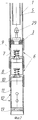
На фиг.1 изображена верхняя часть устройства.Figure 1 shows the upper part of the device.
На фиг.2 изображена нижняя часть устройства.Figure 2 shows the lower part of the device.
Устройство для цементирования хвостовика в скважине состоит из хвостовика 1 (см. фиг.1) с воронкой 2 вверху и опрессовочным седлом 3 внизу, а также колонны труб 4, например колонны насосно-компрессорных труб (см. фиг.2) с ниппелем 5, выполненным с возможностью герметичного взаимодействия с воронкой 2 хвостовика 1 (см. фиг.1). Клапанный узел 6 (см. фиг.2) соединен с нижней частью хвостовика 1 и состоит из верхнего 7 и нижнего 8 корпусов, в которых установлены друг над другом два подпружиненных обратных клапана 9 и 10 соответственно, при этом клапанный узел 6 снизу соединен с башмаком 11, оснащенным фильтром 12, причем на нижний конец башмака 11 навернута алюминиевая заглушка 13. В воронке 2 выполнена кольцевая проточка 14.A device for cementing a liner in a well consists of a liner 1 (see Fig. 1) with a funnel 2 at the top and a crimping
Разъединитель 15 (см. фиг.1 и 2) соединяет между собой верхнюю часть хвостовика 1 и нижнюю часть колонны труб 4 и выполнен в виде полого корпуса 16, расположенного на колонне труб 4 выше ниппеля 5 с кольцевым сужением 17, в котором выполнены радиальные окна 18, и полой втулкой 19, вставленной в кольцевое сужение 17 с возможностью ограниченного упором 20 герметичного перемещения вниз и зафиксированной срезным элементом 21.The disconnector 15 (see figures 1 and 2) connects the upper part of the
В полой втулке 19 на наружной поверхности выполнена конусная сужающаяся вверх поверхность 22, ниже которой выполнены радиальные каналы 23, выполненные с возможностью выхода из кольцевого сужения 17 полого корпуса 16 при перемещении вниз полой втулки 19, внизу которой изготовлено седло 24 под бросовый шар 25.A conical tapering surface 22 is made in the hollow sleeve 19 on the outer surface, below which there are radial channels 23 made with the possibility of exiting the annular narrowing 17 of the hollow body 16 when moving down the hollow sleeve 19, below which a seat 24 is made for the throw ball 25.
В радиальных окнах 18 полого корпуса 16 размещены фиксаторы 26, входящие снаружи в кольцевую проточку 14 воронки 2, - транспортное положение, а изнутри - взаимодействующие с возможностью скольжения с конусной поверхностью 22 полой втулки 19. Фиксаторы 26 выполнены с возможностью перемещения внутрь под действием конусной поверхности 22 полой втулки 19, перемещаемой вниз, с выходом из взаимодействия с кольцевой проточкой 14 воронки 2 - рабочее положение.In the radial windows 18 of the hollow body 16, latches 26 are placed, which are located externally into the annular groove 14 of the funnel 2, the transport position, and from the inside interacting with the possibility of sliding with the conical surface 22 of the hollow sleeve 19. The latches 26 are arranged to move inward under the action of the conical surface 22 of the hollow sleeve 19, moved downward, with the exit from the interaction with the annular groove 14 of the funnel 2 - working position.
С целью исключения несанкционированных перетоков жидкости сопрягаемые поверхности снабжены уплотнительными кольцами 27, 28.In order to exclude unauthorized fluid flows, the mating surfaces are provided with o-rings 27, 28.
Устройство работает следующим образом.The device operates as follows.
Сначала устройство для цементирования хвостовика в скважине, как показано на фиг.1 и 2, монтируют в скважине. Для этого сначала доливают скважину технологической жидкостью, например сточной водой, после чего спускают в нее одну трубу хвостовика 1 (см. фиг.2), оснащенную снизу башмаком 11 с фильтром 12 и алюминиевой заглушкой 13, а также клапанным узлом 6 и опрессовочным седлом 3 и размещенной на нем извлекаемой опрессовочной пробки 29.First, a device for cementing a liner in a well, as shown in FIGS. 1 and 2, is mounted in the well. To do this, first fill the well with technological fluid, for example, waste water, and then lower one
Закачкой технологической жидкости в межколонное пространство скважины (на фиг.1, 2, 3 не показано) производят опрессовку клапанного узла 6, то есть проверяют под давлением, ожидаемым на клапанный узел 6 после продавки цементного раствора в межколонное пространство скважины герметичность работы обратных клапанов 9 и 10, при этом пропуски не допускаются.By pumping the process fluid into the annulus of the well (not shown in FIGS. 1, 2, 3), the
Убедившись в герметичности клапанного узла 6, производят спуск всех труб хвостовика 1 с воронкой 2 (см. фиг.1 и 2) в скважину с доливом в него технологической жидкости, после чего производят опрессовку труб хвостовика 1. Затем в хвостовик 1 с устья скважины спускают любой известный ловильный инструмент (например, ловитель на канате) и производят захват и извлечение извлекаемой опрессовочной пробки 29 из скважины.After verifying the tightness of the
Далее спускают в хвостовик 1 нижний конец колонны труб 4, который должен быть расчетной длины в зависимости от длины хвостовика 1, оборудован центратором (на фиг.1 и 2 не показано) и находится выше на 3-5 метров опрессовочного седла 3 хвостовика 1. После чего приступают к соединению колонны труб 4 с верхним концом хвостовика 1. Производят сборку верхней части устройства, как показано на фиг.1.Next, lower the end of the pipe string 4, which should be the estimated length depending on the length of the
Далее спускают собранную компоновку (хвостовик 1 с колонной труб 4) до упора на забой скважин, что контролируют по индикатору веса (на фиг.1 и 2 не показано), размещенному на устье скважин. Затем производят разъединение колонны труб 4 от хвостовика 1.Next, lower the assembled assembly (
С устья скважины в колонну труб 4 сбрасывают шар 25 (см. фиг.1), который садится на седло 25 и перекрывает центральное отверстие 30 полой втулки 19, после чего доливают колонну труб 4 технологической жидкостью, например сточной водой, и создают в ней с помощью насосного агрегата (например, ЦА-320), размещенного на устье скважины, гидравлическое давление (5-6 МПа), при этом сначала разрушаются срезные элементы 21, например, давление, при котором происходит их разрушение составляет, например, 3-4 МПа, а затем фиксаторы 26, занимающие транспортное положение и расположенные в радиальных каналах 18 полого корпуса 16 и входящие снаружи в кольцевую проточку 14 воронки 2, занимают рабочее положение, в котором фиксаторы 26 перемещаются радиально внутрь под действием конусной поверхности 22 полой втулки 19, перемещаемой вниз под действием гидравлического давления внутри полой втулки 19 и колонне труб 4.From the wellhead into the pipe string 4, a ball 25 is dropped (see FIG. 1), which sits on the seat 25 and overlaps the central hole 30 of the hollow sleeve 19, after which the pipe string 4 is refilled with process fluid, for example, waste water, and is created in it with using a pump unit (for example, ЦА-320) located at the wellhead, hydraulic pressure (5-6 MPa), first, shear elements 21 are destroyed, for example, the pressure at which they are destroyed is, for example, 3-4 MPa and then the latches 26, occupying the transport position and p located in the radial channels 18 of the hollow body 16 and entering from the outside into the annular groove 14 of the funnel 2, occupy a working position in which the latches 26 are moved radially inward under the action of the conical surface 22 of the hollow sleeve 19, which is moved down under the action of hydraulic pressure inside the hollow sleeve 19 and the column pipes 4.
В результате фиксаторы 26 выходят из взаимодействия с кольцевой проточкой 14 воронки 2, при этом радиальные каналы 23 полой втулки 19 оказываются ниже нижнего торца 31 полой втулки 19, за который фиксируются с помощью стопорного пружинного кольца 32.As a result, the latches 26 go out of interaction with the annular groove 14 of the funnel 2, while the radial channels 23 of the hollow sleeve 19 are lower than the lower end 31 of the hollow sleeve 19, for which they are fixed with a snap ring 32.
Приподнимают колонну труб 4 вверх примерно на 1 метр, чтобы убедиться в разъединении колонны труб 4 от хвостовика 1, что контролируется по резкому снижению веса на индикаторе веса, поскольку хвостовик 1 отсоединен от колонны труб 4 и нижним торцом уперт на забой (на фиг.1 и 2 не показано), при этом нижний конец полого корпуса 16 должен герметично с помощью уплотнительных колец 28 взаимодействовать с внутренними стенками хвостовика 11.Raise the pipe string 4 upwards by about 1 meter to make sure that the pipe string 4 is disconnected from the
Заполняют колонну труб 4 (см. фиг.1 и 2) технологической жидкостью и производят вызов циркуляции прямой промывкой по колонне труб 4, радиальным каналам 23 полой втулки 19, хвостовику 1, клапанному узлу 6, фильтру 12 через межколонное пространство скважины на устье. Затем в колонну труб 4 закачивают расчетное количество цементного раствора и продавливают его жидкостью продавки в межколонное пространство скважины (на фиг.1 и 2 не показано).Fill the pipe string 4 (see FIGS. 1 and 2) with process fluid and cause a circulation by direct flushing through the pipe string 4, radial channels 23 of the hollow sleeve 19,
После закачки цементного раствора в межколонное пространство скважины колонну труб 4 с ниппелем 5 поднимают на 1-2 метра так, чтобы нижний конец ниппеля 5 находился выше верхнего торца воронки 2.After pumping cement into the annular space of the well, the pipe string 4 with the
Далее прямой промывкой по колонне труб 4 производят вымывание излишков цементного раствора из внутренней полости хвостовика 1.Next, by direct washing along the pipe string 4, the excess cement mortar is washed out of the inner cavity of the
Затем полностью извлекают из скважины колонну труб 4 с разъединителем 15, выполненным в виде полого корпуса 16, соединенного снизу с ниппелем 5, после чего оставляют скважину на ожидание затвердевания цемента (ОЗЦ).Then, the pipe string 4 with the disconnector 15, made in the form of a hollow body 16 connected from the bottom to the
По окончании времени ОЗЦ опрессовочное седло 3, клапанный узел 6 и алюминиевая заглушка 13 разбуриваются.At the end of the time, the OZZ
Предлагаемое устройство для цементирования хвостовика в скважине обладает простой технологией проведения работ, что позволяет снизить материальные затраты на цементирование хвостовика в скважине, а сокращение спуско-подъемных операций, осуществляемых в процессе цементирования хвостовика, позволит сократить общее время проведения работ и сократить финансовые затраты на ремонт скважины.The proposed device for cementing the liner in the well has a simple technology of work, which allows to reduce the material costs of cementing the liner in the well, and the reduction of hoisting operations carried out in the process of cementing the liner will reduce the total time of work and reduce the financial cost of repairing the well .
Claims (1)
Priority Applications (1)
| Application Number | Priority Date | Filing Date | Title |
|---|---|---|---|
| RU2010115300/03A RU2431732C1 (en) | 2010-04-16 | 2010-04-16 | Device for cementing shank end in well |
Applications Claiming Priority (1)
| Application Number | Priority Date | Filing Date | Title |
|---|---|---|---|
| RU2010115300/03A RU2431732C1 (en) | 2010-04-16 | 2010-04-16 | Device for cementing shank end in well |
Publications (1)
| Publication Number | Publication Date |
|---|---|
| RU2431732C1 true RU2431732C1 (en) | 2011-10-20 |
Family
ID=44999216
Family Applications (1)
| Application Number | Title | Priority Date | Filing Date |
|---|---|---|---|
| RU2010115300/03A RU2431732C1 (en) | 2010-04-16 | 2010-04-16 | Device for cementing shank end in well |
Country Status (1)
| Country | Link |
|---|---|
| RU (1) | RU2431732C1 (en) |
Cited By (2)
| Publication number | Priority date | Publication date | Assignee | Title |
|---|---|---|---|---|
| RU2691037C1 (en) * | 2018-07-13 | 2019-06-07 | Федеральное государственное бюджетное образовательное учреждение высшего образования "Тюменский индустриальный университет" (ТИУ) | Method of multistage pressure testing of pipes in well and device for its implementation |
| RU2809394C1 (en) * | 2023-10-11 | 2023-12-11 | Публичное акционерное общество "Татнефть" имени В.Д. Шашина | Method of pressure testing of pump-compressor pipes in wells with horizontal completion |
-
2010
- 2010-04-16 RU RU2010115300/03A patent/RU2431732C1/en not_active IP Right Cessation
Cited By (2)
| Publication number | Priority date | Publication date | Assignee | Title |
|---|---|---|---|---|
| RU2691037C1 (en) * | 2018-07-13 | 2019-06-07 | Федеральное государственное бюджетное образовательное учреждение высшего образования "Тюменский индустриальный университет" (ТИУ) | Method of multistage pressure testing of pipes in well and device for its implementation |
| RU2809394C1 (en) * | 2023-10-11 | 2023-12-11 | Публичное акционерное общество "Татнефть" имени В.Д. Шашина | Method of pressure testing of pump-compressor pipes in wells with horizontal completion |
Similar Documents
| Publication | Publication Date | Title |
|---|---|---|
| RU2595122C1 (en) | Method for cementing shank in well and device therefor | |
| RU2534690C1 (en) | Universal wellhead packer | |
| RU2414586C1 (en) | Procedure for isolating operations in well and packer equipment | |
| RU2455451C1 (en) | Device to cement tail in well | |
| RU2431732C1 (en) | Device for cementing shank end in well | |
| RU2603110C1 (en) | Method of placing cement plug in cased well and device therefor | |
| RU154295U1 (en) | PACKER DRILLED | |
| RU128896U1 (en) | DEVICE FOR TRANSFER OF WELLS, INCLUDING WATERFILLED, TO OPERATION ON TWO LIFT COLUMNS | |
| RU72715U1 (en) | DEVICE FOR CEMENTING A TAIL IN A WELL | |
| CN106321035B (en) | Full well bore is prevented returning and is told layering water injection tubular column | |
| RU2305173C2 (en) | Method and device for production string sealing during sandy well flushing | |
| RU142771U1 (en) | PACKER | |
| RU2307232C1 (en) | Device for casing pipe cementing inside well | |
| RU2425958C1 (en) | Device for cementing shank in well | |
| CN203230386U (en) | Outer sliding sleeve type oil drain device | |
| RU2709852C1 (en) | Hydraulic device for selective processing | |
| RU158968U1 (en) | DEVICE FOR NIZA OF A STEEL POLYMER-FREE COUPLING FLEXIBLE PIPE FOR OPERATION OF A WELL WITHOUT MUCHING | |
| RU2483192C1 (en) | Drillable packer | |
| CN113090224A (en) | Guide shoe for well cementation and expansion suspension well cementation tubular column | |
| RU58601U1 (en) | Casing Cementing Device | |
| RU2448234C1 (en) | Device for cementing shank in well | |
| RU2795659C1 (en) | Stand for pressure testing of double-row preventer | |
| RU2355866C1 (en) | Facility for cementing tail piece in well | |
| RU2795662C1 (en) | Device for pressure testing of double-row preventer for a well | |
| RU134574U1 (en) | DEVICE FOR CEMENTING A TAIL IN A WELL |
Legal Events
| Date | Code | Title | Description |
|---|---|---|---|
| MM4A | The patent is invalid due to non-payment of fees |
Effective date: 20170417 |