RU2428215C2 - Protector body system - Google Patents
Protector body system Download PDFInfo
- Publication number
- RU2428215C2 RU2428215C2 RU2009111267/14A RU2009111267A RU2428215C2 RU 2428215 C2 RU2428215 C2 RU 2428215C2 RU 2009111267/14 A RU2009111267/14 A RU 2009111267/14A RU 2009111267 A RU2009111267 A RU 2009111267A RU 2428215 C2 RU2428215 C2 RU 2428215C2
- Authority
- RU
- Russia
- Prior art keywords
- needle
- locking means
- sleeve
- protective
- locking
- Prior art date
Links
Images


Classifications
-
- A—HUMAN NECESSITIES
- A61—MEDICAL OR VETERINARY SCIENCE; HYGIENE
- A61M—DEVICES FOR INTRODUCING MEDIA INTO, OR ONTO, THE BODY; DEVICES FOR TRANSDUCING BODY MEDIA OR FOR TAKING MEDIA FROM THE BODY; DEVICES FOR PRODUCING OR ENDING SLEEP OR STUPOR
- A61M25/00—Catheters; Hollow probes
- A61M25/01—Introducing, guiding, advancing, emplacing or holding catheters
- A61M25/06—Body-piercing guide needles or the like
- A61M25/0612—Devices for protecting the needle; Devices to help insertion of the needle, e.g. wings or holders
- A61M25/0637—Butterfly or winged devices, e.g. for facilitating handling or for attachment to the skin
-
- A—HUMAN NECESSITIES
- A61—MEDICAL OR VETERINARY SCIENCE; HYGIENE
- A61M—DEVICES FOR INTRODUCING MEDIA INTO, OR ONTO, THE BODY; DEVICES FOR TRANSDUCING BODY MEDIA OR FOR TAKING MEDIA FROM THE BODY; DEVICES FOR PRODUCING OR ENDING SLEEP OR STUPOR
- A61M25/00—Catheters; Hollow probes
- A61M25/01—Introducing, guiding, advancing, emplacing or holding catheters
- A61M25/06—Body-piercing guide needles or the like
- A61M25/0612—Devices for protecting the needle; Devices to help insertion of the needle, e.g. wings or holders
- A61M25/0631—Devices for protecting the needle; Devices to help insertion of the needle, e.g. wings or holders having means for fully covering the needle after its withdrawal, e.g. needle being withdrawn inside the handle or a cover being advanced over the needle
-
- A—HUMAN NECESSITIES
- A61—MEDICAL OR VETERINARY SCIENCE; HYGIENE
- A61M—DEVICES FOR INTRODUCING MEDIA INTO, OR ONTO, THE BODY; DEVICES FOR TRANSDUCING BODY MEDIA OR FOR TAKING MEDIA FROM THE BODY; DEVICES FOR PRODUCING OR ENDING SLEEP OR STUPOR
- A61M5/00—Devices for bringing media into the body in a subcutaneous, intra-vascular or intramuscular way; Accessories therefor, e.g. filling or cleaning devices, arm-rests
- A61M5/178—Syringes
- A61M5/31—Details
- A61M5/32—Needles; Details of needles pertaining to their connection with syringe or hub; Accessories for bringing the needle into, or holding the needle on, the body; Devices for protection of needles
- A61M5/3205—Apparatus for removing or disposing of used needles or syringes, e.g. containers; Means for protection against accidental injuries from used needles
- A61M5/321—Means for protection against accidental injuries by used needles
- A61M5/3243—Means for protection against accidental injuries by used needles being axially-extensible, e.g. protective sleeves coaxially slidable on the syringe barrel
- A61M5/3245—Constructional features thereof, e.g. to improve manipulation or functioning
- A61M2005/3247—Means to impede repositioning of protection sleeve from needle covering to needle uncovering position
-
- A—HUMAN NECESSITIES
- A61—MEDICAL OR VETERINARY SCIENCE; HYGIENE
- A61M—DEVICES FOR INTRODUCING MEDIA INTO, OR ONTO, THE BODY; DEVICES FOR TRANSDUCING BODY MEDIA OR FOR TAKING MEDIA FROM THE BODY; DEVICES FOR PRODUCING OR ENDING SLEEP OR STUPOR
- A61M5/00—Devices for bringing media into the body in a subcutaneous, intra-vascular or intramuscular way; Accessories therefor, e.g. filling or cleaning devices, arm-rests
- A61M5/178—Syringes
- A61M5/31—Details
- A61M5/32—Needles; Details of needles pertaining to their connection with syringe or hub; Accessories for bringing the needle into, or holding the needle on, the body; Devices for protection of needles
- A61M5/3205—Apparatus for removing or disposing of used needles or syringes, e.g. containers; Means for protection against accidental injuries from used needles
- A61M5/321—Means for protection against accidental injuries by used needles
- A61M5/3243—Means for protection against accidental injuries by used needles being axially-extensible, e.g. protective sleeves coaxially slidable on the syringe barrel
- A61M5/3271—Means for protection against accidental injuries by used needles being axially-extensible, e.g. protective sleeves coaxially slidable on the syringe barrel with guiding tracks for controlled sliding of needle protective sleeve from needle exposing to needle covering position
Abstract
Description
Настоящее изобретение относится к устройству защитного приспособления для иглы, содержащему иглу, например, одноразового медицинского устройства, и защитный корпус для иглы, в котором игла крепится к втулке иглы, способной перемещаться относительно защитного корпуса между положением использования, в котором наконечник иглы, по меньшей мере, выступает за пределы защитного корпуса, и втянутым положением, в котором игла полностью находится в защитном корпусе.The present invention relates to a needle protector device comprising a needle, for example, a disposable medical device, and a needle protector in which the needle is attached to a needle sleeve capable of moving relative to the protector between a use position in which the needle tip is at least protrudes beyond the protective housing, and retracted position in which the needle is completely in the protective housing.
Устройство защитного приспособления для иглы такого типа хорошо известно и помогает предотвратить случайный контакт медицинского работника или любого другого человека с острым наконечником иглы после использования одноразового медицинского устройства. Такой случайный контакт с использованной иглой может вызвать передачу болезни типа гепатита, ВИЧ и т.д.A needle guard device of this type is well known and helps to prevent accidental contact of a medical professional or any other person with a sharp needle tip after using a disposable medical device. Such accidental contact with a used needle can cause transmission of a disease such as hepatitis, HIV, etc.
Растущая частота появления патогенов, переносимых кровью, таких как вирус иммунодефицита человека, ВИЧ (HIV), в сочетании с вирусом гепатита B (HBV) и вирусом гепатита C (HCV), представляет для медицинских работников профессиональную опасность, беспрецедентную в современной медицине. Риск заразиться HIV из-за травмы наконечником иглы составляет приблизительно 1 к 100, но для тех, кто заражается инфекцией HIV в результате травмы наконечником иглы, зараженным HIV, риск становится равным 1 к 1. Риск заразиться более инфекционным HBV в результате травмы наконечником иглы лежит в диапазоне от 1 к 6 до 1 к 20.The increasing incidence of blood borne pathogens, such as human immunodeficiency virus, HIV (HIV), combined with hepatitis B virus (HBV) and hepatitis C virus (HCV), poses a medical hazard that is unprecedented in modern medicine. The risk of contracting HIV due to a needle tip injury is approximately 1 to 100, but for those who become infected with HIV as a result of an HIV needle tip injury, the risk becomes 1 to 1. The risk of contracting a more infectious HBV due to a needle tip injury lies in the range from 1 to 6 to 1 to 20.
Существуют некоторые другие патогены, переносимые кровью, которые передаются через кровь и жидкости тела. Присутствие любого из этих патогенов у пациентов создает риск для медицинских работников при выполнении инвазивных процедур. Инфекционные болезни в настоящее время находятся на третьем месте среди причин смертности после болезней сердца и рака, тогда как десять лет назад они занимали пятое место, что указывает на возрастающую потребность в более безопасных медицинских устройствах.There are some other bloodborne pathogens that are transmitted through the blood and body fluids. The presence of any of these pathogens in patients poses a risk to healthcare providers when performing invasive procedures. Infectious diseases are currently in third place among the causes of death after heart disease and cancer, while ten years ago they took fifth place, indicating an increasing need for safer medical devices.
По мере того как популяция инфицированных людей растет, все больше людей будут пользоваться услугами медицинских работников, что создает дополнительные риски передачи болезней от пациентов медицинским работникам. Также использование одноразовых медицинских устройств увеличивается приблизительно на 10% в год. Дополнительно в мире выявлено заметное количество передачи болезней от пациентов к пациентам в медицинских учреждениях. Недавние данные предполагают, что прямой вклад в это увеличение вносят несоответствующие способы контроля инфекций, в том числе несоответствующее использование медицинских устройств, имеющих иглы, лекарственных пузырьков, содержащих большое число доз, и отказ от смены защитных перчаток и принадлежностей при обслуживании каждого нового пациента.As the population of infected people grows, more and more people will use the services of medical workers, which creates additional risks of transmission of diseases from patients to medical workers. Also, the use of disposable medical devices is increasing by approximately 10% per year. Additionally, a significant amount of disease transmission from patients to patients in medical institutions has been revealed in the world. Recent evidence suggests that inappropriate infection control methods make a direct contribution to this increase, including the inappropriate use of medical devices with needles, drug vials containing a large number of doses, and the refusal to change protective gloves and accessories when servicing each new patient.
Медицинские работники все больше и больше подвергаются риску передачи болезней, поскольку медсестры выполняют множество инвазивных подкожных процедур, таких как инъекции лекарственных средств, взятие крови и вставление катетеров для внутривенного (I.V) вливания. Медсестры и другой медицинский персонал обычно травмируются открытой колющей частью иглы после использования на пациенте. Критическим временем, в течение которого чрескожная травма может произойти, является время с момента, когда игла вынута из пациента или из места внутривенного введения, до времени, когда загрязненная игла безопасно уничтожается.Health care providers are increasingly at risk of transmission of disease, as nurses perform many invasive subcutaneous procedures, such as injecting drugs, taking blood, and inserting catheters for intravenous (I.V) infusion. Nurses and other medical personnel are usually injured by the open stitching part of the needle after use on the patient. The critical time during which a transdermal injury can occur is the time from when the needle was removed from the patient or from the site of intravenous administration to the time when the contaminated needle is safely destroyed.
До быстрого распространения HIV и серологического гепатита травма концом стержня иглы считалась обычной частью обеспечения ухода за пациентом. Травма концом стержня иглы в настоящее время несет угрожающие жизни последствия и работники здравоохранения ежедневно должны жить с этим страхом.Prior to the rapid spread of HIV and serological hepatitis, trauma to the tip of the needle shaft was considered a common part of patient care. Injury at the end of the needle shaft now has life-threatening consequences and health workers must live with this fear daily.
Существует потребность в дешевом безопасном защитном устройстве иглы универсального применения.There is a need for a cheap, safe needle guard device for universal use.
Задачей изобретения является обеспечение устройства защитного приспособления для иглы, дающего надежную защиту от случайного укола иглой, например одноразовым медицинским устройством, и которое можно легко и дешево изготавливать.The objective of the invention is to provide a protective device for the needle, which provides reliable protection against accidental injection by a needle, for example a disposable medical device, and which can be easily and cheaply manufactured.
Эта задача решается устройством защитного приспособления для иглы, имеющего признаки пункта 1 формулы изобретения.This problem is solved by the device of the protective device for the needle having the characteristics of paragraph 1 of the claims.
Устройство защитного приспособления для иглы в соответствии с изобретением содержит иглу, например, одноразового медицинского устройства и защитный корпус иглы, в котором игла крепится к втулке иглы, которая может перемещаться относительно защитного корпуса между положением использования, в котором наконечник иглы, по меньшей мере, выступает за пределы защитного корпуса, и втянутым положением, в котором игла находится в защитном корпусе. Устройство защитного приспособления для иглы дополнительно содержит запирающий механизм, выполненный с возможностью гарантированного размещения втулки иглы внутри защитного корпуса, когда втулка иглы находится во втянутом положении.The needle protector device according to the invention comprises a needle, for example, a disposable medical device and a needle protector, in which the needle is attached to the needle sleeve, which can be moved relative to the protector between the use position in which the needle tip protrudes at least beyond the protective housing, and the retracted position in which the needle is in the protective housing. The needle protector device further comprises a locking mechanism configured to guarantee the placement of the needle sleeve inside the protective case when the needle sleeve is in the retracted position.
Другими словами, изобретение предлагает устройство защитного приспособления для иглы, надежно запирающее иглу в защитном корпусе с помощью механизма зацепления. Запирающий механизм эффективно предотвращает высовывание иглы по неосторожности из защитного корпуса. Таким образом, защита от случайного укола иглой резко повышается. Следовательно, устройство защитного приспособления для иглы, соответствующее изобретению, обеспечивает безопасное уничтожение иглы после ее использования.In other words, the invention provides a needle guard device that locks the needle securely in the protective housing by means of an engagement mechanism. The locking mechanism effectively prevents the needle from protruding inadvertently from the protective housing. Thus, the protection against accidental needle pricking is dramatically increased. Therefore, the needle guard device of the invention provides for the safe destruction of the needle after use.
Следует отметить, что в контексте этого изобретения термин "игла" содержит любой предмет, имеющий острый наконечник, способный вызывать чрескожную травму. Конкретно, в этом контексте термин "игла" понимается как относящийся к игле не только в буквальном смысле слова, но также и к лезвию, которое имеет острый конец.It should be noted that in the context of this invention, the term “needle” contains any object having a sharp tip capable of causing percutaneous injury. Specifically, in this context, the term “needle” is understood to refer to a needle not only in the literal sense of the word, but also to a blade that has a sharp end.
К примерам одноразовых медицинских устройств, в которых может использоваться устройство защитного приспособления для иглы, относятся не только устройства, используемые для взятия крови у пациента или донора, или для вливания текучих сред пациенту, такие как комплекты для взятия крови (PSV-комплекты с наконечниками Люэра), мешки с иглами для взятия крови, комплекты для вен черепа и фистульные иглы, но также скальпели с лезвиями.Examples of disposable medical devices that may use a needle protector include not only devices used to collect blood from a patient or donor, or to infuse fluids to a patient, such as blood collection kits (PSV kits with Luer tips ), bags with needles for taking blood, sets for skull veins and fistula needles, but also scalpels with blades.
Если устройство защитного приспособления для иглы используется в комплекте для взятия крови, то втулка иглы может быть крыльчатым корпусом, к которому присоединяется трубка из ПХВ для сбора крови, берущейся у пациента.If the needle guard is used in the blood collection kit, then the needle sleeve may be a vane housing to which a PVC tube is attached to collect the blood taken from the patient.
В соответствии с предпочтительным вариантом осуществления, запирающий механизм содержит, по меньшей мере, одну пару первого запирающего средства и второго запирающего средства, сцепляющихся друг с другом, когда втулка иглы находится во втянутом положении, в котором первое запирающее средство обеспечивается на втулке иглы, и второе запирающее средство обеспечивается на защитном корпусе.According to a preferred embodiment, the locking mechanism comprises at least one pair of first locking means and a second locking means engaged with each other when the needle sleeve is in the retracted position in which the first locking means is provided on the needle sleeve, and a second locking means is provided on the protective housing.
По меньшей мере, две пары первого запирающего средства и второго запирающего средства могут быть установлены на одной и той же стороне устройства защитного приспособления для иглы и разделены друг от друга, если смотреть в осевом направлении иглы, когда втулка иглы находится во втянутом положении.At least two pairs of the first locking means and the second locking means can be mounted on the same side of the needle guard device and separated from each other when viewed in the axial direction of the needle when the needle sleeve is in the retracted position.
Альтернативно или дополнительно, по меньшей мере, одна пара первого запирающего средства и второго запирающего средства может быть установлена на первой стороне устройства защитного приспособления для иглы, в то время как, по меньшей мере, одна пара первого запирающего средства и второго запирающего средства может быть установлена на второй стороне устройства защитного приспособления для иглы напротив первой стороны, когда втулка иглы находится во втянутом положении.Alternatively or additionally, at least one pair of the first locking means and the second locking means may be mounted on the first side of the needle guard device, while at least one pair of the first locking means and the second locking means may be installed on the second side of the needle guard device opposite the first side when the needle sleeve is in the retracted position.
Устройство защитного приспособления для иглы особенно дешево для производства, если первое запирающее средство изготавливается вместе со втулкой иглы. Альтернативно первое запирающее средство может быть изготовлено на отдельном элементе, например кольце, которое крепится к втулке иглы.The needle guard device is particularly cheap to manufacture if the first locking means is made together with the needle sleeve. Alternatively, the first locking means can be made on a separate element, for example a ring, which is attached to the needle sleeve.
Предпочтительно, первое запирающее средство определяет поверхность, обращенную к наконечнику иглы, у которой, по меньшей мере, часть поверхности расширяется в плоскости, обычно перпендикулярной игле. Этим достигается наиболее эффективно возможное взаимодействие между первым запирающим средством и вторым запирающим средством.Preferably, the first locking means defines a surface facing the tip of the needle, in which at least a portion of the surface expands in a plane, usually perpendicular to the needle. This achieves the most effectively possible interaction between the first locking means and the second locking means.
В соответствии с предпочтительным вариантом осуществления, первое запирающее средство содержит выступ, выступающий из втулки иглы.According to a preferred embodiment, the first locking means comprises a protrusion protruding from the needle sleeve.
Например, первое запирающее средство может обычно иметь форму носика или скоса с радиальным размером, возрастающим в направлении наконечника иглы.For example, the first locking means may typically be in the form of a spout or bevel with a radial dimension increasing in the direction of the needle tip.
Предпочтительно, первое запирающее средство изготавливается таким, что радиальный размер запирающего средства может уменьшаться вод действием возвращающей силы. Например, первое запирающее средство может быть изготовлено из материала, обладающего упругими свойствами. Это может облегчить перемещение втулки иглы во внутреннем канале защитного корпуса.Preferably, the first locking means is made such that the radial size of the locking means can be reduced by the action of a restoring force. For example, the first locking means may be made of a material having elastic properties. This can facilitate the movement of the needle sleeve in the inner channel of the protective housing.
Первое запирающее средство может быть установлено в области ближнего конца втулки иглы. Такое расположение особенно выгодно, когда втулка иглы является крыльчатым корпусом.The first locking means may be installed in the region of the proximal end of the needle sleeve. This arrangement is particularly advantageous when the needle sleeve is a wing body.
Альтернативно первое запирающее средство может быть установлено в области удаленного конца втулки иглы. Такое расположение особенно выгодно, когда втулка иглы имеет форму, подобную прямоугольному параллелепипеду.Alternatively, the first locking means may be installed in the region of the distal end of the needle sleeve. This arrangement is particularly advantageous when the needle sleeve has a shape similar to a rectangular parallelepiped.
В последнем случае первое запирающее средство может быть изготовлено из выступа втулки иглы, обращенного к наконечнику иглы, в котором выступ предпочтительно определяет поверхность втулки иглы, обращенной к концу иглы, так что, по меньшей мере, часть поверхности приходится на плоскость, в целом, перпендикулярную к игле.In the latter case, the first locking means may be made of a protrusion of the needle sleeve facing the tip of the needle, in which the protrusion preferably defines the surface of the sleeve of the needle facing the end of the needle, so that at least part of the surface is on a plane generally perpendicular to the needle.
В соответствии с дополнительным вариантом осуществления, второе запирающее средство содержит отверстие, например щель в защитном корпусе, которая выполнена с возможностью приема первого запирающего средства, когда втулка иглы находится во втянутом положении. Второе запирающее средство в форме отверстия в защитном корпусе особенно выгодно, когда первое запирающее средство изготовлено из выступа, выступающего из втулки иглы, и обладает упругими свойствами, так что оно может входит в зацепление в отверстии, если правильно расположено, сцепляя таким образом между собой втулку иглы и защитный корпус.According to a further embodiment, the second locking means comprises an opening, for example a slot in the protective housing, which is adapted to receive the first locking means when the needle sleeve is in the retracted position. The second locking means in the form of an aperture in the protective housing is particularly advantageous when the first locking means is made of a protrusion protruding from the needle sleeve and is resilient so that it can engage in the hole, if correctly positioned, thereby locking the sleeve together needles and protective case.
В соответствии с альтернативным вариантом осуществления, второе запирающее средство содержит запирающий язычок, вытянутый в направлении ближнего конца защитного корпуса и выполненный с возможностью сцепления с первым запирающим средством, когда втулка иглы находится во втянутом положении.According to an alternative embodiment, the second locking means comprises a locking tongue extended in the direction of the proximal end of the protective housing and adapted to engage with the first locking means when the needle sleeve is in the retracted position.
Предпочтительно, запирающий язычок обладает упругими свойствами и вытянут в направлении внутренности защитного корпуса, так что он выталкивается наружу первым запирающим средством или втулкой иглы по мере того как втулка иглы перемещается в направлении ее втянутого положения, и защелкивается позади первого запирающего средства как только втулка иглы попадает в свое втянутое положение. В случае такого упругого запирающего язычка первое запирающее средство в форме выступа, выступающего из втулки иглы, может обладать упругими свойствами, однако, это не обязательно.Preferably, the locking tab has elastic properties and extends toward the inside of the protective housing so that it is pushed out by the first locking means or the needle sleeve as the needle sleeve moves in the direction of its retracted position and latches behind the first locking means as soon as the needle sleeve enters into its drawn position. In the case of such an elastic locking tongue, the first locking means in the form of a protrusion protruding from the needle sleeve may have elastic properties, however, this is not necessary.
Стоимость производства устройства защитного приспособления для иглы может быть дополнительно уменьшена, если запирающий язычок изготавливается целиком вместе с защитным корпусом.The cost of manufacturing a needle guard device can be further reduced if the locking tongue is made entirely with the shield body.
Защитный корпус предпочтительно содержит направляющее средство для направления первого запирающего средства в зацепление со вторым запирающим средством, когда втулка иглы двигается в направлении ее втянутого положения. Направляющее средство помогает обеспечить надежное зацепление между первым запирающим средством и вторым запирающим средством, в частности если первое запирающее средство является выступом, выступающим из втулки иглы, а второе запирающее средство является отверстием для приема выступа или запирающего язычка для зацепления позади выступа.The protective housing preferably comprises guiding means for guiding the first locking means into engagement with the second locking means when the needle sleeve moves in the direction of its retracted position. The guiding means helps to ensure reliable engagement between the first locking means and the second locking means, in particular if the first locking means is a protrusion protruding from the needle sleeve and the second locking means is an opening for receiving the protrusion or locking tongue for engagement behind the protrusion.
Чтобы достигнуть еще более надежного запирания иглы внутри защитного корпуса, запирающий механизм предпочтительно содержит удерживающий элемент, гарантирующий зацепление пары первого запирающего средства и второго запирающего средства.In order to achieve an even more reliable locking of the needle inside the protective housing, the locking mechanism preferably comprises a holding element that ensures that the pair of the first locking means and the second locking means are engaged.
Удерживающий элемент может быть изготовлен со стороны защитного приспособления на стороне, противоположной паре первого запирающего средства и второго запирающего средства. Тем самым удерживающий элемент помогает предотвратить расцепление первого запирающего элемента со вторым запирающим средством. Дополнительно растягивание действует как направляющая для втулки иглы, когда втулка иглы входит во внутренний канал плоской части защитного корпуса. Удерживающий элемент может, например, быть удлинением защитного корпуса, выступающим из ближней части защитного корпуса в направлении удаленного конца защитного корпуса.The retaining element may be made from the side of the protective device on the side opposite to the pair of the first locking means and the second locking means. Thereby, the holding member helps prevent the first locking element from releasing with the second locking means. Additionally, the stretching acts as a guide for the needle sleeve when the needle sleeve enters the inner channel of the flat portion of the protective housing. The holding element may, for example, be an extension of the protective housing protruding from the proximal portion of the protective housing towards the distal end of the protective housing.
В соответствии с дополнительным вариантом осуществления устройства защитного приспособления для иглы защитный корпус содержит вытянутую часть, имеющую форму одной половины трубы, разрезанной, по меньшей мере, приблизительно наполовину в осевом направлении. Защитный корпус такого вида особенно выгоден, если втулка иглы является крыльчатым корпусом, поскольку открытая форма вытянутой части защитного корпуса позволяет крыльям крыльчатого корпуса выступать из защитного корпуса, в то время как игла, прикрепленная к крыльчатому корпусу, попадает внутрь вытянутой части, когда втулка иглы движется в направлении ее втянутого положения.According to a further embodiment of the needle guard device, the guard body comprises an elongated portion having the shape of one half pipe cut at least about half in the axial direction. A protective case of this kind is particularly advantageous if the needle sleeve is a winged body, since the open shape of the elongated portion of the protective body allows the wings of the winged body to protrude from the protective body, while the needle attached to the winged body enters the extended part when the needle sleeve moves in the direction of its retracted position.
Кроме того, защитный корпус предпочтительно содержит трубчатую часть в области дальнего конца защитного корпуса и/или плоской части в области ближнего конца защитного корпуса. Трубчатая часть предотвращает залипание иглы сбоку при выходе из защитного корпуса, таким образом дополнительно увеличивая защитный эффект устройства защитного приспособления для иглы.In addition, the protective housing preferably comprises a tubular portion in the region of the distal end of the protective housing and / or a flat part in the region of the proximal end of the protective housing. The tubular portion prevents sticking of the needle on the side when exiting the protective case, thereby further increasing the protective effect of the needle protector device.
Плоская часть может содержать первую и вторую части, определяющие внутренний канал, в который попадает втулка иглы, когда втулка иглы переходит во втянутое положение. Чтобы дополнительно снизить производственные расходы, первая и вторая части могут быть интегрально изготовлены и соединены друг с другом пленочной петлей.The flat part may comprise first and second parts defining an inner channel into which the needle sleeve enters when the needle sleeve enters the retracted position. To further reduce production costs, the first and second parts can be integrally fabricated and connected to each other by a film loop.
В собранном состоянии первая и вторая части могут прикрепляться друг к другу посредством, по меньшей мере, одного из запирающегося механизма, клея или сварки.In the assembled state, the first and second parts can be attached to each other by at least one of the locking mechanism, glue or welding.
В соответствии с дополнительным альтернативным вариантом осуществления устройства защитного приспособления для иглы, фактически вся длина защитного корпуса, как видно в осевом направлении, имеет обычно трубчатую форму. Этот тип защитного корпуса может использоваться, например, когда втулка иглы не имеет каких-либо крыльев, а имеет, например, основную форму в виде прямоугольного параллелепипеда.According to a further alternative embodiment of the needle guard device, virtually the entire length of the guard body, as seen in the axial direction, is usually tubular. This type of protective housing can be used, for example, when the needle sleeve does not have any wings, but has, for example, the main shape in the form of a rectangular parallelepiped.
Предпочтительные варианты осуществления изобретения описаны в последующем описании и на сопроводительных чертежах, на которых:Preferred embodiments of the invention are described in the following description and in the accompanying drawings, in which:
Фиг.1 - вид в перспективе верхней стороны устройства защитного приспособления для иглы, соответствующего изобретению, согласно первому варианту осуществления, в котором игла выступает из защитного корпуса.Figure 1 is a perspective view of the upper side of the needle guard device of the invention according to the first embodiment, in which the needle protrudes from the guard.
Фиг.2 - вид в перспективе нижней стороны устройства защитного приспособления для иглы, показанного на Фиг.1, в котором игла выступает из защитного корпуса.FIG. 2 is a perspective view of the lower side of the needle guard device shown in FIG. 1, in which the needle protrudes from the guard.
Фиг.3 - вид в плане снизу устройства защитного приспособления, показанного на Фиг.1, с иглой, выступающей из защитного корпуса.Figure 3 is a plan view from below of the device of the protective device shown in Figure 1, with a needle protruding from the protective housing.
Фиг.4 - вид в разрезе устройства защитного приспособления для иглы, показанного на Фиг.1, по линии X-X на Фиг.3, с иглой, выступающей из защитного корпуса.FIG. 4 is a sectional view of the needle guard device shown in FIG. 1 along the line X-X in FIG. 3 with a needle protruding from the guard.
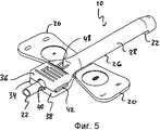
Фиг.5 - вид в перспективе сверху устройства защитного приспособления для иглы, показанного на Фиг.1, с иглой, убранной и запертой в защитном корпусе.FIG. 5 is a top perspective view of a needle guard device shown in FIG. 1 with a needle retracted and locked in a protective case.
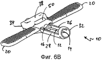
Фиг.6A,6B - виды в перспективе нижней стороны устройства защитного приспособления для иглы, показанного на Фиг.1, с иглой, убранной и запертой в защитном корпусе.6A, 6B are perspective views of the lower side of the needle guard device shown in FIG. 1 with the needle retracted and locked in the protective case.
Фиг.7 - вид в разрезе устройства защитного приспособления для иглы, показанного на Фиг.1, по линии Y-Y на Фиг.7A, с иглой, убранной и запертой в защитном корпусе.FIG. 7 is a sectional view of the needle guard device shown in FIG. 1 along the line Y-Y in FIG. 7A, with the needle retracted and locked in the protective case.
Фиг.8 - вид в разрезе устройства защитного приспособления для иглы, показанного на Фиг.1, по осевому направлению устройства, с иглой, убранной и запертой в защитном корпусе.Fig. 8 is a sectional view of the needle guard device shown in Fig. 1 in the axial direction of the device, with the needle retracted and locked in the protective case.
Фиг.9A - увеличенный участок вида в разрезе, показанного на Фиг.8, показывающий более подробно запирающий механизм для запирания иглы в защитном корпусе.FIG. 9A is an enlarged sectional view of FIG. 8, showing in more detail a locking mechanism for locking the needle in the protective housing.
Фиг.9B - вид в разрезе, показывающий альтернативную версию запирающего механизма.9B is a cross-sectional view showing an alternative version of the locking mechanism.
Фиг.10 - вид в разрезе плоской части защитного корпуса устройства защитного приспособления для иглы, показанного на Фиг.1.Figure 10 is a view in section of a flat part of the protective housing of the device of the protective device for the needle shown in Figure 1.
Фиг.11 - вид в перспективе сверху защитного корпуса устройства защитного приспособления для иглы, показанного на Фиг.1.11 is a top perspective view of the protective housing of the needle guard device shown in FIG. 1.
Фмг.12A, 12B - вид в перспективе с нижней стороны защитного корпуса устройства защитного приспособления для иглы, показанного на Фиг.1.Fmg 12A, 12B is a perspective view from the bottom side of the protective housing of the needle guard device shown in FIG. 1.
Фиг.13 - вид в перспективе устройства защитного приспособления для иглы, соответствующего изобретению, в соответствии со вторым вариантом осуществления, в котором игла выступает из защитного корпуса.FIG. 13 is a perspective view of a needle guard device of the invention in accordance with a second embodiment in which the needle protrudes from the guard.
Фиг.14A, 14B - вид в перспективе устройства защитного приспособления для иглы, показанного на Фиг.13.Figa, 14B is a perspective view of the device of the protective device for the needle shown in Fig.13.
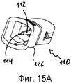
Фиг.15A, 15B - вид в перспективе устройства защитного приспособления для иглы, показанного на Фиг.13, с иглой, убранной и запертой в защитном корпусе.Figa, 15B is a perspective view of the device of the protective device for the needle shown in Fig.13, with the needle retracted and locked in a protective case.
Фиг.16 - вид в разрезе устройства защитного приспособления для иглы, показанного на Фиг.13, в осевом направлении устройства, с иглой, убранной и запертой в защитном корпусе.Fig. 16 is a sectional view of the needle guard device shown in Fig. 13 in the axial direction of the device, with the needle retracted and locked in the protective case.
Фиг.17 - увеличенный участок сечения, показанного на Фиг.16, показывающий более подробно запирающий механизм для запирания иглы в защитном корпусе.Fig. 17 is an enlarged sectional view of Fig. 16, showing in more detail the locking mechanism for locking the needle in the protective housing.
Фиг.18 - вид в разрезе устройства защитного приспособления для иглы, показанного на Фиг.13, в плоскости, перпендикулярной осевому направлению устройства, с иглой, убранной и запертой в защитном корпусе.Fig. 18 is a sectional view of the needle guard device shown in Fig. 13 in a plane perpendicular to the axial direction of the device, with the needle retracted and locked in the protective case.
Фиг.19 - вид в разрезе устройства защитного приспособления для иглы, соответствующего изобретению, согласно третьему варианту осуществления, в осевом направлении устройства, с иглой, убранной и запертой в защитном корпусе.Fig. 19 is a cross-sectional view of the needle guard device of the invention according to the third embodiment, in the axial direction of the device, with the needle retracted and locked in the protective case.
Фиг.20 - увеличенный участок вида в разрезе, показанного на Фиг.19, показывающий более подробно запирающий механизм для запирания иглы в защитном корпусе.Fig.20 is an enlarged sectional view of the section shown in Fig.19, showing in more detail the locking mechanism for locking the needle in the protective housing.
На Фиг.1-12 показано устройство 10 защитного приспособления для иглы, соответствующее первому варианту осуществления изобретения.1-12, a
Устройство 10 защитного приспособления для иглы является частью одноразового медицинского устройства, например комплекта для взятия крови, имеющего подкожную иглу 12, и предназначается для предотвращения случайного контакта медицинского персонала или любого другого человека с острым наконечником 14 иглы 12 после использования одноразового медицинского устройства.The
В этом контексте конец иглы 12, имеющий острый наконечник 14, обозначается как удаленный конец, тогда как противоположный конец иглы обозначается как ближний конец. Аналогично ориентация частей других конструктивных элементов, обращенных в направлении к наконечнику 14 иглы, будет упоминаться как удаленная, тогда как ориентация частей этих конструктивных элементов, обращенных в противоположном направлении, будет упоминаться как ближняя.In this context, the end of the
Игла 12 проходит в осевом направлении, определяя таким образом осевое направление устройства 10 защитного приспособления для иглы. Направление, перпендикулярное к осевому направлению, обозначается как радиальное.The
В области ее ближнего конца игла 12 присоединена, например приклеена, к втулке 16 иглы. Втулка 16 иглы в этом варианте осуществления изготовлена из крыльчатого корпуса, имеющего трубчатый основной корпус 18 и два крыла 20, которые направлены в противоположных радиальных направлениях от основного корпуса 18. Крылья 20 могут быть изготовлены либо как одно целое с основным корпусом 18 либо могут быть отдельными элементами, прикрепленными к основному корпусу 18.In the region of its proximal end, the
Один конец PVC-трубки 22 крепится, например приклеивается, к ближней торцевой части втулки 16 иглы. Другой конец PVC-трубки 22 может быть, например, присоединен к мешку для сбора крови (не показан) или любому другому компоненту, чтобы облегчить поток жидкости, такой как лекарственное средство или кровь, к пациенту или донору или от них.One end of the
Как можно видеть на Фиг.4, 7, 8 и 9, запирающий выступ 24 смонтирован на верхней боковой стороне основного корпуса 18 втулки 16 иглы в ближней ее области. Запирающий выступ 24 изготавливается вместе с основным корпусом 18 и обычно имеет форму носика или скоса, радиальный размер которого увеличивается в направлении наконечника 14 иглы 12. Удаленная поверхность 25 запирающего выступа 24, обращенная к наконечнику 14 иглы, располагается в плоскости, в целом, перпендикулярной осевому направлению.As can be seen in FIGS. 4, 7, 8 and 9, the locking
Устройство 10 защитного приспособления для иглы дополнительно содержит защитный корпус 26, в котором располагается и может скользить основной корпус 18 втулки 16 иглы. Более конкретно защитный корпус 26 содержит вытянутую часть 28, имеющую форму половины трубы, разрезанной, по меньшей мере, приблизительно наполовину в осевом направлении, определяя таким образом закрытую верхнюю сторону и открытую нижнюю сторону вытянутой части 28. Открытая нижняя сторона вытянутой части 28 позволяет крыльям 20 втулки 16 иглы проходить сбоку от защитного корпуса 26, когда основной корпус 18 втулки 16 иглы попадает в вытянутую часть 28.The
Как хорошо видно на Фиг.12A и 12B, в вытянутой части 28 могут обеспечиваться направляющие рельсы 30, проходящие в осевом направлении и выполненные с возможностью управления ориентацией запирающего выступа 24, когда втулка 16 иглы перемещается вдоль вытянутой части 28.12A and 12B, in the
В области удаленного конца вытянутой части 28 защитный корпус 26 содержит трубчатую часть 32, предотвращающую выход иглы 12 из защитного корпуса 26 сбоку.In the region of the distal end of the
В области ближнего торца вытянутой части 28 защитный корпус 26 содержит плоскую часть 34, изготовленную из верхней части 36 и нижней части 38. Верхняя и нижняя части 36, 38 вместе определяют внутренний канал 40, через который проходит PVC-трубка 22 и в который может быть помещена ближняя торцевая часть основного корпуса 18 втулки 16 иглы.In the region of the near end of the
Как можно видеть из Фиг.10-12, верхняя и нижняя части 36, 38 изготовлены как одно целое и соединены друг с другом пленочной петлей 42. Кроме того, верхняя и нижняя части 36, 38 скрепляются друг с другом запирающим механизмом 44. Альтернативно или дополнительно они могут быть соединены друг с другом клеем или сваркой.As can be seen from FIGS. 10-12, the upper and
Во внутреннем канале 40 плоской части 34 предусмотрены направляющие рельсы 46, которые выравнены с направляющими рельсами 30 вытянутой части 28, чтобы управлять ориентацией запирающего выступа 24, когда втулка 16 иглы входит в плоскую часть 34.In the
Запирающий язычок 48 обеспечивается в верхней части 36 из плоской части 34. Запирающий язычок 48 полностью изготавливается вместе с верхней частью 36 и обладает упругими свойствами. Запирающий язычок 48 выравнивается с внутренним каналом 40 и проходит в направлении ближнего конца защитного корпуса 26 и во внутреннем канале 40 (Фиг.4, 8, 9A и 9B).A locking
В целом, запирающий язычок 48 может иметь различные формы (Фиг.9A и 9B). Однако обязательным требованием является то, что запирающий язычок 48 должен иметь форму, которая должна быть такой, чтобы его свободный конец упирался в дальнюю поверхность 25 запирающего выступа 24, обращенного к наконечнику 14 иглы, когда игла полностью находится в защитном корпусе 26, как показано на Фиг.8, 9A и 9B.In general, the
Удерживающий элемент 50 изготовлен на нижней части 38 плоской части 34. Удерживающий элемент 50 имеет удлинение в форме язычка, которое проходит в направлении от дальнего конца нижней части 38 в осевом направлении.The holding
Функционирование устройства 10 защитного приспособления для иглы происходит следующим образом:The functioning of the
В исходном состоянии устройства 10 защитного приспособления для иглы втулка 16 иглы находится в самом крайнем удаленном положении, упомянутом здесь как положение использования, в котором крылья 20 втулки 16 иглы находятся рядом с трубчатой частью 32 защитного корпуса и игла 12 выступает из защитного корпуса 32.In the initial state of the
Медицинский работник держит крылья 20, прикрепленные к втулке 16 иглы и прокалывает кожу пациента иглой 12 так, что игла 12 попадает в вену пациента. По мере того как игла 12 входит в вену, кровь устремляется в иглу 12 и через основной корпус 18 втулки 16 иглы в PVC-трубку 22. Кровь собирается в мешок для взятия крови или вакуумную трубку, присоединенную к другому концу PVC-трубки 22. Альтернативно устройство может использоваться для вливания пациенту жидкостей или лекарственных препаратов.The medical professional holds the
После того как требуемое количество крови взято, игла 12 вытаскивается из вены, держа крылья 20. По мере того как игла 12 вытягивается из пациента, она входит в защитный корпус 26. В то же самое время крыльчатый корпус движется назад в направлении плоской части 34 защитного корпуса 26.After the required amount of blood has been taken, the
Когда ближняя концевая часть основного корпуса 18 крыльчатого корпуса прошла во внутренний канал 40 плоской части 34 защитного корпуса 26, запирающий выступ 24 втулки 16 иглы зацепляется за запирающий язычок 48 защитного корпуса 26. Запирающий язычок 48 движется по наклонной сторона запирающего выступа 24 и тем самым выталкивается наружу.When the proximal end portion of the wing housing
Когда втулка 16 иглы приняла положение, в котором игла 12 полностью убрана в защитный корпус 26, здесь упоминаемое как втянутое положение, запирающий выступ 24 проходит запирающий язычок 48, так что запирающий язычок 48 защелкивается внутри благодаря его упругим свойствам и входит в зацепление позади запирающего выступа 24, тем самым предотвращая движение втулки 16 иглы к удаленному концу защитного корпуса 26.When the
Во втянутом положении втулки 16 иглы удерживающий элемент 50 выступает за часть нижней стороны втулки 16 иглы. Таким образом удерживающий элемент 50 не только действует в качестве направляющей, помогающей втулке 16 иглы правильно войти во внутренний канал 40 из плоской части 34, но также и предотвращает движение втулки 16 иглы в радиальном направлении, в направлении от запирающего язычка 48, которое может вызвать расцепление запирающего выступа 24 и запирающего язычка 48 и может в конечном счете привести к случайному выходу иглы 12 из защитного корпуса.In the retracted position of the
Следовательно, во втянутом положении втулки 16 иглы игла 12 безопасно запирается внутри защитного корпуса 26 и комплект для взятия крови может надежно уничтожаться без опасности укола иглой любого человека.Therefore, in the retracted position of the
На Фиг.13-18 показано устройство 110 защитного приспособления для иглы, соответствующее второму варианту осуществления, которое может использоваться в одноразовом медицинском устройстве, таком как мешок для взятия крови с иглой. Элементы, соответствующие подобным элементам в приведенном выше первом варианте осуществления, будут обозначаться теми же самыми ссылочными номерами, увеличенными на 100.13-18, a
Устройство 110 защитного приспособления для иглы, соответствующее второму варианту осуществления, содержит иглу 112, имеющую на удаленном конце наконечник 114 иглы. Однако в отличие от первого варианта осуществления, игла 112 прикреплена не к крыльчатому корпусу, а к втулке 116 иглы, которая обычно имеет форму прямоугольного параллелепипеда и которая имеет на своих противоположных сторонах слегка вогнутые поверхности 152 для манипуляций с ней.The
Как лучше всего видно на Фиг.16 и 17, выступ 154 изготовлен на втулке 116 иглы, которая определяет удаленную поверхность 125, обращенную к наконечнику 114 иглы и расположенную в плоскости, обычно перпендикулярной осевому направлению иглы 112.As best seen in FIGS. 16 and 17, the
На ближнем конце втулка 116 иглы соединяется с трубкой 122, изготовленной из PVC.At the proximal end, the
Устройство 110 защитного приспособления для иглы дополнительно содержит защитный корпус 126, который является трубчатым по всей его длине, как видно в осевом направлении иглы 114, когда втулка 116 иглы помещается в защитный корпус 126 (Фиг.14А-15B).The
Защитный корпус 126 обычно имеет прямоугольное внутреннее сечение, видное в плоскости, перпендикулярной осевому направлению. Внутреннее сечение защитного корпуса 126 подогнано к внешнему сечению втулки 116 иглы так, что втулка 116 иглы может входить в защитный корпус 126 и двигаться внутри защитного корпуса 126 к его ближнему концу.The
В области ближнего конца защитного корпуса 126 два запирающих язычка 148 со свойствами, подобными пружине, изготавливаются на противоположных сторонах защитного корпуса 126. Запирающие язычки 148 изготавливаются вместе с защитным корпусом 126 и вытянуты в осевом направлении к ближнему концу защитного корпуса 126. В то же самое время запирающие язычки 148 изогнуты внутрь, то есть они вытянуты в радиальном направлении внутрь во внутреннюю полость, определенную защитным корпусом 126.In the region of the proximal end of the
Функционирование устройства 110 защитного приспособления для иглы происходит следующим образом:The operation of the
В исходном состоянии устройства 110 защитного приспособления для иглы игла 112 и втулка 116 иглы находятся снаружи защитного корпуса 126 в положении использования. В этом положении игла 112 может быть введена в пациента или донора.In the initial state of the
После того как игла 112 вынута из пациента, защитный корпус 126 надвигается на втулку 116 иглы так, что втулка 116 иглы и игла 112 входят в защитный корпус 126. Натягивая PVC-трубку 122, втулка 116 перемещается внутри защитного корпуса 126 в направлении его ближнего конца.After the
В то время как втулка 116 иглы движется в направлении ближнего конца защитного корпуса 126, втулка 116 иглы входит в зацепление с запирающими язычками 148 и толкает запирающие язычки 148 наружу, преодолевая возвращающую силу запирающих язычков 148.While the
Когда втулка 116 иглы доходит до области ближнего конца защитного корпуса 126, запирающие язычки 148 проходят удаленный выступ 154 втулки 116 иглы и защелкиваются внутри защитного корпуса 126, таким образом входя в зацепление позади поверхности 125 втулки 116 иглы.When the
В этой ситуации втулка 116 иглы устанавливается во втянутое положение, в котором игла 112 полностью находится в защитном корпусе 126 и игла 112 надежно заперта внутри защитного корпуса 126 запирающими язычками 148, препятствующими движению втулки 116 иглы в осевом направлении к удаленному концу защитного корпуса. Таким образом, медицинское устройство может быть благополучно уничтожено без опасности укола иглой какого-либо человека.In this situation, the
На Фиг.19 и 20 показано устройство 110 защитного приспособления для иглы, соответствующее третьему варианту осуществления, которое отличается от упомянутого описанного выше устройства 110 защитного приспособления для иглы, соответствующего второму варианту осуществления, только формой запирающих язычков 148.19 and 20 show the
Запирающие язычки 148 в третьем варианте осуществления имеют клиновидный профиль с их внешней поверхностью, обычно выравненной с внешней поверхностью защитного корпуса 126, в то время как размер запирающих язычков 148 по радиальному направлению увеличивается в направлении свободных концов запирающих язычков 148.The locking
Обычно возможны альтернативные формы запирающих язычков 148. Однако обязательным требованием является то, чтобы запирающие язычки 148 должны иметь такую форму, чтобы их свободные концы упирались в удаленную поверхность 125 выступа 154 втулки 116 иглы, когда игла 112 полностью находится в защитном корпусе 126.Alternative forms of locking
Дополнительно следует отметить, что возможны варианты осуществления устройства защитного приспособления для иглы, в которых втулка иглы содержит как выступ, который входит в зацепление с одним или более запирающих язычков защитного корпуса, так и выступающая часть, которая входит в зацепление с запирающим язычком или отверстием в защитном корпусе, когда втулка иглы находится во втянутом положении.Additionally, it should be noted that there are possible embodiments of a needle guard device in which the needle sleeve comprises both a protrusion that engages with one or more locking tabs of the protective housing, and a protruding portion that engages with the locking tab or hole in protective housing when the needle sleeve is retracted.
ССЫЛОЧНЫЕ НОМЕРАREFERENCE NUMBERS
10 Устройство защитного приспособления для иглы10 Needle guard
12 Игла12 Needle
14 Наконечник иглы14 needle tip
16 Втулка иглы16 needle bushing
18 Основной корпус18 Main body
20 Крыло20 wing
22 PVC-трубка22 PVC tube
24 Запирающая выступающая часть24 Locking protruding part
25 Удаленная поверхность25 Remote surface
26 Защитный корпус26 Protective housing
28 Вытянутая часть28 Elongated part
30 Направляющие рельсы30 Guide rails
32 Трубка32 Handset
34 Плоская часть34 flat part
36 Верхняя часть36 Upper
38 Нижняя часть38 Bottom
40 Канал40 Channel
42 Пленочная петля42 Film loop
44 Защелкивающий механизм44 latch mechanism
46 Направляющие рельсы46 Guide rails
48 Запирающий язычок48 Locking tongue
50 Удерживающий элемент50 holding element
110 Устройство защитного приспособления для иглы110 Needle guard
112 Игла112 Needle
114 Наконечник иглы114 needle tip
116 Втулка иглы116 needle bushing
118 Основной корпус118 Main building
122 PVC-трубка122 PVC tube
125 Удаленная поверхность125 Remote surface
126 Защитный корпус126 protective housing
148 Запирающий язычок148 Locking tongue
152 Поверхность для манипуляций152 Surface for handling
154 Выступ.154 Projection.
Claims (22)
в котором игла (12) прикреплена к втулке (16) иглы, которая выполнена с возможностью перемещения относительно защитного корпуса (26) между положением использования, в котором, по меньшей мере, наконечник (14) иглы (12) находится вне защитного корпуса (26), и втянутым положением, в котором игла (12) полностью находится в защитном корпусе (26),
при этом устройство защитного приспособления для иглы дополнительно содержит запирающий механизм, выполненный с возможностью крепления втулки (16) иглы внутри защитного корпуса (26), когда втулка (16) иглы находится во втянутом положении, и
запирающий механизм содержит, по меньшей мере, одну пару из первого и второго запирающих средств (24, 48), входящую в зацепление друг с другом, когда втулка (16) иглы находится во втянутом положении, причем первое запирающее средство (24) обеспечено на втулке (16) иглы и второе запирающее средство (48) обеспечено на защитном корпусе (26),
отличающееся тем, что
первое запирающее средство (24) имеет, в основном, форму носика или скоса с радиальным размером, увеличивающимся в направлении наконечника (14) иглы (12), изготовлено так, что радиальный размер первого запирающего средства может уменьшаться под действием возвращающей силы, и установлено в области ближайшего конца втулки (16) иглы.1. The device (10) of the protective device for the needle, containing the needle (12) and the protective housing (26) for the needle (12),
in which the needle (12) is attached to the sleeve (16) of the needle, which is configured to move relative to the protective housing (26) between the position of use, in which at least the tip (14) of the needle (12) is located outside the protective housing (26 ), and the retracted position, in which the needle (12) is completely in the protective case (26),
wherein the needle protector device further comprises a locking mechanism configured to fasten the needle sleeve (16) inside the protective case (26) when the needle sleeve (16) is in the retracted position, and
the locking mechanism comprises at least one pair of first and second locking means (24, 48) engaged with each other when the needle sleeve (16) is in the retracted position, the first locking means (24) being provided on the sleeve (16) needles and a second locking means (48) are provided on the protective housing (26),
characterized in that
the first locking means (24) is mainly in the shape of a nose or bevel with a radial size increasing in the direction of the tip (14) of the needle (12), is made so that the radial size of the first locking means can decrease under the action of the restoring force, and is set to the area of the nearest end of the needle sleeve (16).
Applications Claiming Priority (2)
| Application Number | Priority Date | Filing Date | Title |
|---|---|---|---|
| IN1921/DEL/2006 | 2006-08-28 | ||
| IN1921DE2006 | 2006-08-28 |
Related Child Applications (1)
| Application Number | Title | Priority Date | Filing Date |
|---|---|---|---|
| RU2011116510/14A Division RU2587957C2 (en) | 2006-08-28 | 2007-08-28 | Housing of protective device |
Publications (2)
| Publication Number | Publication Date |
|---|---|
| RU2009111267A RU2009111267A (en) | 2010-10-10 |
| RU2428215C2 true RU2428215C2 (en) | 2011-09-10 |
Family
ID=38896844
Family Applications (1)
| Application Number | Title | Priority Date | Filing Date |
|---|---|---|---|
| RU2009111267/14A RU2428215C2 (en) | 2006-08-28 | 2007-08-28 | Protector body system |
Country Status (11)
| Country | Link |
|---|---|
| US (1) | US9199063B2 (en) |
| EP (2) | EP2056905B1 (en) |
| CN (3) | CN102512746B (en) |
| AU (1) | AU2007291049B2 (en) |
| BR (2) | BRPI0716265B1 (en) |
| CA (1) | CA2661301C (en) |
| CL (1) | CL2008002105U1 (en) |
| DE (1) | DE202007019267U1 (en) |
| ES (1) | ES2438595T3 (en) |
| RU (1) | RU2428215C2 (en) |
| WO (1) | WO2008026037A2 (en) |
Families Citing this family (27)
| Publication number | Priority date | Publication date | Assignee | Title |
|---|---|---|---|---|
| JP4994775B2 (en) | 2006-10-12 | 2012-08-08 | 日本コヴィディエン株式会社 | Needle point protector |
| US8323249B2 (en) | 2009-08-14 | 2012-12-04 | The Regents Of The University Of Michigan | Integrated vascular delivery system |
| ES2841914T3 (en) * | 2009-09-22 | 2021-07-12 | Poly Medicure Ltd | Needle guard |
| US8814833B2 (en) | 2010-05-19 | 2014-08-26 | Tangent Medical Technologies Llc | Safety needle system operable with a medical device |
| US8771230B2 (en) | 2010-05-19 | 2014-07-08 | Tangent Medical Technologies, Llc | Integrated vascular delivery system |
| EP2509674B1 (en) * | 2010-09-07 | 2015-09-02 | Poly Medicure Limited | Needle protector assembly |
| ITPD20110070A1 (en) * | 2011-03-04 | 2012-09-05 | Axel Srl | MEDICAL DEVICE FOR THE INTRODUCTION OF A CATHETER IN A BLOOD VASE. |
| EP2517751B8 (en) | 2011-04-27 | 2018-02-28 | Kpr U.S., Llc | Safety IV catheter assemblies |
| WO2013048975A1 (en) | 2011-09-26 | 2013-04-04 | Covidien Lp | Safety catheter |
| EP2760521B1 (en) | 2011-09-26 | 2016-01-06 | Covidien LP | Safety iv catheter and needle assembly |
| WO2013056223A1 (en) | 2011-10-14 | 2013-04-18 | Covidien Lp | Safety iv catheter assembly |
| CN202314697U (en) * | 2011-11-03 | 2012-07-11 | 上海维朴芮国际贸易有限公司 | Safe butterfly-shaped venous infusion needle |
| WO2013068855A1 (en) * | 2011-11-11 | 2013-05-16 | Poly Medicure Limited | Protector cover assembly for needle of disposable medical device |
| CN104822404B (en) * | 2012-10-23 | 2018-09-28 | 波利麦迪克有限公司 | Needle set safety device |
| US10350366B2 (en) | 2013-02-01 | 2019-07-16 | Nxstage Medical, Inc. | Safe cannulation devices, methods, and systems |
| CN103191496B (en) * | 2013-04-10 | 2014-10-29 | 上海维朴芮国际贸易有限公司 | Butterfly-type needle assembly and butterfly-type needle protective sleeve |
| JP6461174B2 (en) | 2014-02-04 | 2019-01-30 | アイシーユー・メディカル・インコーポレーテッド | Self-priming system and self-priming method |
| CN104274190B (en) * | 2014-04-11 | 2015-05-27 | 上海金塔医用器材有限公司 | Safety blood taking needle |
| WO2016015364A1 (en) * | 2014-07-28 | 2016-02-04 | 上海金塔医用器材有限公司 | Safe blood sampling needle |
| CN111150902B (en) * | 2014-08-29 | 2022-02-08 | 医疗部件有限公司 | Hubeier safety needle |
| USD804021S1 (en) * | 2015-02-27 | 2017-11-28 | Medical Components, Inc. | Huber safety needle |
| USD804022S1 (en) * | 2015-02-27 | 2017-11-28 | Medical Components, Inc. | Huber safety needle |
| MX2018011221A (en) | 2016-03-18 | 2018-11-22 | Medical Components Inc | Huber safety needle. |
| USD828653S1 (en) | 2016-12-14 | 2018-09-11 | Brandon Penland | Treatment applicator |
| EP3755405B1 (en) | 2018-02-19 | 2023-12-13 | Becton Dickinson France | An injection system comprising a syringe and a protective assembly |
| US11883124B2 (en) | 2020-07-31 | 2024-01-30 | Vicky Chaleff | Disposable medical device covers |
| DE102021115556A1 (en) | 2021-06-16 | 2022-12-22 | Sarstedt Ag & Co. Kg | Safety Needle Assembly |
Family Cites Families (24)
| Publication number | Priority date | Publication date | Assignee | Title |
|---|---|---|---|---|
| US4676783A (en) * | 1985-09-03 | 1987-06-30 | The University Of Virginia Alumni Patents Foundation | Retractable safety needle |
| US4781692A (en) * | 1985-09-03 | 1988-11-01 | The University Of Virginia Alumni Patents Foundation | Retractable safety needles |
| JPH0637580B2 (en) * | 1987-03-16 | 1994-05-18 | 東海カ−ボン株式会社 | Carbon black for rubber compounding |
| US5085639A (en) * | 1988-03-01 | 1992-02-04 | Ryan Medical, Inc. | Safety winged needle medical devices |
| US5147326A (en) | 1988-06-28 | 1992-09-15 | Sherwood Medical Company | Combined syringe and needle shield and method of manufacture |
| ATE134886T1 (en) * | 1988-09-30 | 1996-03-15 | David S Utterberg | PROTECTED NEEDLE UNIT |
| ATE146362T1 (en) * | 1991-01-14 | 1997-01-15 | Precision Dynamics Corp | CANNULA PROTECTION |
| US5306258A (en) | 1991-04-03 | 1994-04-26 | Fuente Ricardo L De | Safety syringe and method of using same |
| AUPM432794A0 (en) | 1994-03-09 | 1994-03-31 | Noble House Group Pty Ltd | Protection assembly |
| US5683365A (en) | 1995-06-07 | 1997-11-04 | Johnson & Johnson Medical, Inc. | Tip protection device |
| US5562631A (en) | 1995-06-07 | 1996-10-08 | Johnson & Johnson Medical, Inc. | Catheter arrangement with interlocking sequenced guarding members for protecting cannula |
| AUPO915797A0 (en) | 1997-09-11 | 1997-10-02 | Noble House Group Pty Ltd | Needle guard and assembly |
| US6776776B2 (en) * | 1999-10-14 | 2004-08-17 | Becton, Dickinson And Company | Prefillable intradermal delivery device |
| US6632201B1 (en) * | 1999-11-17 | 2003-10-14 | Baxter International Inc. | Locking needle protector |
| AU9419101A (en) * | 2000-10-06 | 2002-04-22 | Jms Co Ltd | Wing retraction type mis-piercing preventer and winged needle having the mis-piercing preventer |
| ITBO20010497A1 (en) | 2001-07-31 | 2003-01-31 | Delta Med S R L | PROTECTION DEVICE FOR NEEDLE-CANNULA |
| DE10156587B4 (en) | 2001-11-20 | 2004-05-06 | Sarstedt Ag & Co. | Cover housing of a wing cannula |
| CN1463758A (en) | 2002-06-17 | 2003-12-31 | 上海康德莱企业发展集团有限公司 | Transfusion syringe having safety apparatus |
| US7566327B2 (en) | 2002-08-09 | 2009-07-28 | Fenwal, Inc. | Needle protector |
| US7175610B2 (en) * | 2003-03-20 | 2007-02-13 | Nipro Corporation | Protector sheath for winged-needle |
| JP4648615B2 (en) | 2003-04-04 | 2011-03-09 | 株式会社ジェイ・エム・エス | Medical needle device with a winged shield |
| US7201740B2 (en) * | 2004-07-01 | 2007-04-10 | Becton, Dickinson And Company | Forward-shielding blood collection set |
| ITMI20041471A1 (en) * | 2004-07-21 | 2004-10-21 | Sergio Restelli | STANDARD SYRINGE SAFETY KIT FOR SINGLE USE SAFETY SYRINGE |
| US8118786B2 (en) * | 2006-03-29 | 2012-02-21 | Kawasumi Laboratories, Inc. | Guarded medical winged needle assembly |
-
2007
- 2007-08-28 CN CN201110308424.0A patent/CN102512746B/en active Active
- 2007-08-28 EP EP07804843.6A patent/EP2056905B1/en active Active
- 2007-08-28 CN CN2007800321941A patent/CN101636190B/en active Active
- 2007-08-28 CN CN201110155038.2A patent/CN102274561B/en active Active
- 2007-08-28 AU AU2007291049A patent/AU2007291049B2/en active Active
- 2007-08-28 EP EP09009642.1A patent/EP2108394B1/en active Active
- 2007-08-28 BR BRPI0716265A patent/BRPI0716265B1/en active IP Right Grant
- 2007-08-28 US US12/438,717 patent/US9199063B2/en active Active
- 2007-08-28 DE DE202007019267U patent/DE202007019267U1/en not_active Expired - Lifetime
- 2007-08-28 ES ES07804843.6T patent/ES2438595T3/en active Active
- 2007-08-28 CA CA2661301A patent/CA2661301C/en not_active Expired - Fee Related
- 2007-08-28 WO PCT/IB2007/002472 patent/WO2008026037A2/en active Application Filing
- 2007-08-28 BR BRPI0722417A patent/BRPI0722417B8/en active IP Right Grant
- 2007-08-28 RU RU2009111267/14A patent/RU2428215C2/en active
-
2008
- 2008-07-17 CL CL2008002105U patent/CL2008002105U1/en unknown
Also Published As
| Publication number | Publication date |
|---|---|
| CA2661301A1 (en) | 2008-03-06 |
| EP2056905B1 (en) | 2013-11-27 |
| CN102274561A (en) | 2011-12-14 |
| EP2108394B1 (en) | 2017-12-06 |
| BRPI0722417B8 (en) | 2021-06-22 |
| RU2009111267A (en) | 2010-10-10 |
| RU2011116510A (en) | 2012-11-10 |
| EP2108394A1 (en) | 2009-10-14 |
| US20100082002A1 (en) | 2010-04-01 |
| EP2056905A2 (en) | 2009-05-13 |
| BRPI0716265A2 (en) | 2011-12-06 |
| CN102512746B (en) | 2014-05-14 |
| BRPI0722417A2 (en) | 2012-12-25 |
| DE202007019267U1 (en) | 2011-10-19 |
| CN101636190A (en) | 2010-01-27 |
| WO2008026037A3 (en) | 2008-05-29 |
| AU2007291049A1 (en) | 2008-03-06 |
| BRPI0722417B1 (en) | 2019-10-08 |
| US9199063B2 (en) | 2015-12-01 |
| BRPI0716265B1 (en) | 2016-05-24 |
| CN101636190B (en) | 2011-12-07 |
| CL2008002105U1 (en) | 2009-01-16 |
| CN102274561B (en) | 2014-06-18 |
| WO2008026037A2 (en) | 2008-03-06 |
| CN102512746A (en) | 2012-06-27 |
| ES2438595T3 (en) | 2014-01-17 |
| CA2661301C (en) | 2013-07-16 |
| AU2007291049B2 (en) | 2012-04-19 |
Similar Documents
| Publication | Publication Date | Title |
|---|---|---|
| RU2428215C2 (en) | Protector body system | |
| EP1638637B1 (en) | Safety needle shield apparatus | |
| JP3200232U (en) | Needle protector assembly | |
| JP6235030B2 (en) | Needle safety assembly | |
| RU2587957C2 (en) | Housing of protective device |