RU2428131C2 - Envelope for creating possibility for insertion and removal of device for anastomotic ring application - Google Patents
Envelope for creating possibility for insertion and removal of device for anastomotic ring application Download PDFInfo
- Publication number
- RU2428131C2 RU2428131C2 RU2006114818/14A RU2006114818A RU2428131C2 RU 2428131 C2 RU2428131 C2 RU 2428131C2 RU 2006114818/14 A RU2006114818/14 A RU 2006114818/14A RU 2006114818 A RU2006114818 A RU 2006114818A RU 2428131 C2 RU2428131 C2 RU 2428131C2
- Authority
- RU
- Russia
- Prior art keywords
- ring
- deployment mechanism
- ring deployment
- anastomotic
- surgical instrument
- Prior art date
Links
Images


Classifications
-
- A—HUMAN NECESSITIES
- A61—MEDICAL OR VETERINARY SCIENCE; HYGIENE
- A61B—DIAGNOSIS; SURGERY; IDENTIFICATION
- A61B17/00—Surgical instruments, devices or methods, e.g. tourniquets
- A61B17/04—Surgical instruments, devices or methods, e.g. tourniquets for suturing wounds; Holders or packages for needles or suture materials
-
- A—HUMAN NECESSITIES
- A61—MEDICAL OR VETERINARY SCIENCE; HYGIENE
- A61B—DIAGNOSIS; SURGERY; IDENTIFICATION
- A61B17/00—Surgical instruments, devices or methods, e.g. tourniquets
- A61B17/11—Surgical instruments, devices or methods, e.g. tourniquets for performing anastomosis; Buttons for anastomosis
- A61B17/1114—Surgical instruments, devices or methods, e.g. tourniquets for performing anastomosis; Buttons for anastomosis of the digestive tract, e.g. bowels or oesophagus
-
- A—HUMAN NECESSITIES
- A61—MEDICAL OR VETERINARY SCIENCE; HYGIENE
- A61B—DIAGNOSIS; SURGERY; IDENTIFICATION
- A61B17/00—Surgical instruments, devices or methods, e.g. tourniquets
- A61B17/11—Surgical instruments, devices or methods, e.g. tourniquets for performing anastomosis; Buttons for anastomosis
- A61B17/115—Staplers for performing anastomosis in a single operation
-
- A—HUMAN NECESSITIES
- A61—MEDICAL OR VETERINARY SCIENCE; HYGIENE
- A61B—DIAGNOSIS; SURGERY; IDENTIFICATION
- A61B17/00—Surgical instruments, devices or methods, e.g. tourniquets
- A61B2017/00367—Details of actuation of instruments, e.g. relations between pushing buttons, or the like, and activation of the tool, working tip, or the like
-
- A—HUMAN NECESSITIES
- A61—MEDICAL OR VETERINARY SCIENCE; HYGIENE
- A61B—DIAGNOSIS; SURGERY; IDENTIFICATION
- A61B17/00—Surgical instruments, devices or methods, e.g. tourniquets
- A61B2017/00831—Material properties
- A61B2017/00867—Material properties shape memory effect
-
- A—HUMAN NECESSITIES
- A61—MEDICAL OR VETERINARY SCIENCE; HYGIENE
- A61B—DIAGNOSIS; SURGERY; IDENTIFICATION
- A61B17/00—Surgical instruments, devices or methods, e.g. tourniquets
- A61B17/04—Surgical instruments, devices or methods, e.g. tourniquets for suturing wounds; Holders or packages for needles or suture materials
- A61B17/0401—Suture anchors, buttons or pledgets, i.e. means for attaching sutures to bone, cartilage or soft tissue; Instruments for applying or removing suture anchors
- A61B2017/0408—Rivets
-
- A—HUMAN NECESSITIES
- A61—MEDICAL OR VETERINARY SCIENCE; HYGIENE
- A61B—DIAGNOSIS; SURGERY; IDENTIFICATION
- A61B17/00—Surgical instruments, devices or methods, e.g. tourniquets
- A61B17/28—Surgical forceps
- A61B17/29—Forceps for use in minimally invasive surgery
- A61B2017/2901—Details of shaft
- A61B2017/2905—Details of shaft flexible
Abstract
Description
ОБЛАСТЬ ТЕХНИКИ, К КОТОРОЙ ОТНОСИТСЯ ИЗОБРЕТЕНИЕFIELD OF THE INVENTION
Изобретение относится, в общем, к хирургии, в частности к устройству для выполнения хирургической операции на пищеварительной системе.The invention relates, in General, to surgery, in particular to a device for performing surgery on the digestive system.
УРОВЕНЬ ТЕХНИКИ ИЗОБРЕТЕНИЯBACKGROUND OF THE INVENTION
Процентная доля населения мира, страдающего от патологического ожирения, постоянно увеличивается. Лица с выраженным ожирением могут быть подвержены повышенному риску сердечных заболеваний, инсульта, диабета, заболевания легких и травм. Вследствие влияния патологического ожирения на жизнь пациента способы лечения патологического ожирения стали объектом интенсивных исследований.The percentage of the world's population suffering from morbid obesity is constantly increasing. Persons with severe obesity may be at increased risk for heart disease, stroke, diabetes, lung disease, and injury. Due to the influence of pathological obesity on the patient's life, methods for treating pathological obesity have become the subject of intensive research.
Один известный способ лечения патологического ожирения включает в себя использование анастомотических колец. Устройства для наложения анастомотических колец известны в данной области техники. Устройства данного типа обычно выполнены так, чтобы вставлять сжатое анастомотическое кольцо в анастомотическое отверстие, образованное между соседними стенками из ткани желудочно-кишечного тракта. Данные устройства для наложения могут использовать механизм развертывания кольца, содержащий расширительный элемент, который приводится в действие, как только сжатое кольцо помещают в анастомотическое отверстие, и вынуждает анастомотическое кольцо расширяться из его сжатого положения в форме цилиндра в задействованное положение в форме полой заклепки.One known method for treating morbid obesity involves the use of anastomotic rings. Devices for applying anastomotic rings are known in the art. Devices of this type are usually designed to insert a compressed anastomotic ring into the anastomotic hole formed between adjacent walls of the tissue of the gastrointestinal tract. These overlay devices may use a ring deployment mechanism containing an expansion member that is actuated as soon as the compressed ring is placed in the anastomotic hole and causes the anastomotic ring to expand from its compressed cylinder-shaped position to the engaged position in the form of a hollow rivet.
В случае с некоторыми традиционными устройствами для наложения анастомотических колец, которые используют пальцы или аналогичные элементы для расширения анастомотических колец, возможен захват ткани между пальцами устройства для наложения, когда данное устройство вставляют вблизи соседних стенок из ткани желудочно-кишечного тракта. Аналогично, возможен захват ткани в механизме развертывания во время извлечения устройства из места анастомоза. Захват ткани между пальцами может приводить к нежелательным последствиям, например сдавливанию или разрыву ткани или даже к нарушению целостности анастомоза.In the case of some conventional devices for applying anastomotic rings that use fingers or similar elements to expand the anastomotic rings, it is possible to capture tissue between the fingers of the application device when this device is inserted near adjacent walls of the gastrointestinal tissue. Similarly, tissue capture in the deployment mechanism is possible during removal of the device from the site of the anastomosis. Capture of tissue between the fingers can lead to undesirable consequences, for example squeezing or tearing of the tissue or even to a violation of the integrity of the anastomosis.
Некоторые устройства для наложения анастомотических колец, известные в данной области техники, содержат трубчатую оболочку, которая расположена с возможностью скольжения на удлиненном стержне. Трубчатая оболочка обычно находится в положении поверх механизма развертывания кольца, когда устройство вставляют вблизи места анастомоза и во время извлечения устройства, и может быть отведена, чтобы обеспечить возможность развертывания кольца. Таким образом, может быть желательно наличие устройства для наложения анастомотических колец, которое обеспечивает снижение вероятности захвата ткани в механизм развертывания кольца в устройстве, но не обязательно требует времени и механизма для отведения оболочки с пальцев устройства.Some devices for applying anastomotic rings, known in the art, comprise a tubular shell that slides on an elongated shaft. The tubular casing is typically in a position over the ring deployment mechanism when the device is inserted close to the anastomosis site and during removal of the device and can be retracted to allow deployment of the ring. Thus, it may be desirable to have a device for applying anastomotic rings, which reduces the likelihood of tissue being trapped in the ring deployment mechanism in the device, but does not necessarily require time and mechanism to remove the shell from the fingers of the device.
СУЩНОСТЬ ИЗОБРЕТЕНИЯSUMMARY OF THE INVENTION
В одном варианте осуществления устройство для наложения анастомотического кольца содержит рукоятку, прикрепленную к удлиненному стержню. Удлиненный стержень содержит механизм развертывания анастомотического кольца. Оболочка покрывает механизм развертывания кольца, когда его вставляют вблизи места анастомоза и когда его извлекают из места, и тем самым предотвращает захват ткани в механизм развертывания. Данный вариант осуществления не требует от хирурга отдельного приведения в действие оболочки и механизма развертывания кольца.In one embodiment, the device for applying an anastomotic ring comprises a handle attached to an elongated shaft. The elongated shaft contains the deployment mechanism of the anastomotic ring. The shell covers the deployment mechanism of the ring when it is inserted near the site of the anastomosis and when it is removed from the site, and thereby prevents tissue from being taken into the deployment mechanism. This embodiment does not require the surgeon to separately actuate the sheath and ring deployment mechanism.
В другом варианте осуществления устройство для наложения анастомотического кольца содержит рукоятку, прикрепленную к удлиненному стержню, содержащему проксимальный участок и дистальный участок. Дистальный участок удлиненного стержня содержит механизм развертывания кольца. Механизм развертывания кольца содержит множество пальцев, которые могут перемещаться из незадействованного положения продольного совмещения с удлиненным стержнем во второе положение, в котором пальцы срабатывают наружу от продольной оси удлиненного стержня, чтобы привести в действие участок анастомотического кольца. Устройство дополнительно содержит оболочку, которая выполнена, чтобы охватывать пальцы механизма развертывания кольца, и которая выполнена, чтобы перемещаться с пальцами из первого положения продольного совмещения с удлиненным стержнем во второе положение, в котором пальцы выдвигаются из продольного совмещения со стержнем. Поэтому устройство может предотвратить захват ткани в пальцы механизма развертывания кольца.In another embodiment, the device for applying an anastomotic ring includes a handle attached to an elongated shaft containing a proximal section and a distal section. The distal portion of the elongated shaft comprises a ring deployment mechanism. The ring deployment mechanism comprises a plurality of fingers that can move from an unused longitudinal alignment position with the elongated shaft to a second position in which the fingers operate outward from the longitudinal axis of the elongated shaft to actuate a portion of the anastomotic ring. The device further comprises a shell that is designed to enclose the fingers of the deployment mechanism of the ring, and which is made to move with the fingers from the first position of the longitudinal alignment with the elongated shaft to the second position, in which the fingers extend from the longitudinal alignment with the rod. Therefore, the device can prevent tissue from being trapped in the fingers of the ring deployment mechanism.
В еще одном варианте осуществления устройство для наложения анастомотического кольца содержит рукоятку, соединенную с механизмом развертывания кольца удлиненным стержнем. Механизм развертывания кольца содержит продольную оконечность и центральный участок. Устройство содержит приводной механизм, который выполнен, чтобы перемещать продольную оконечность механизма развертывания кольца к центральному участку с приведением тем самым в действие участка анастомотического кольца. Устройство для наложения дополнительно содержит оболочку, которая выполнена, чтобы охватывать продольную оконечность механизма развертывания кольца, и которая выполнена, чтобы перемещаться вместе с продольной оконечностью к центру устройства. Это обеспечивает возможность безопасной вставки и извлечения устройства без введения этапов отведения оболочки в процесс развертывания анастомотического кольца.In yet another embodiment, the device for applying an anastomotic ring comprises a handle connected to the ring deployment mechanism by an elongated shaft. The ring deployment mechanism comprises a longitudinal extremity and a central portion. The device comprises a drive mechanism, which is designed to move the longitudinal tip of the deployment mechanism of the ring to the Central section, thereby actuating the section of the anastomotic ring. The overlay device further comprises a shell that is configured to cover the longitudinal tip of the ring deployment mechanism, and that is configured to move with the longitudinal tip toward the center of the device. This provides the ability to safely insert and remove the device without introducing the steps of the removal of the shell in the deployment process of the anastomotic ring.
КРАТКОЕ ОПИСАНИЕ ЧЕРТЕЖЕЙBRIEF DESCRIPTION OF THE DRAWINGS
Прилагаемые чертежи, которые включены в настоящее описание и составляют его часть, иллюстрируют варианты исполнения изобретения и вместе с вышеприведенным общим описанием и нижеприведенным подробным описанием вариантов исполнения служат для пояснения принципов настоящего изобретения.The accompanying drawings, which are incorporated in and constitute a part of the present description, illustrate embodiments of the invention and, together with the above general description and the following detailed description of embodiments, serve to explain the principles of the present invention.
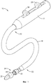
Фиг.1 - вид в перспективе устройства для наложения анастомотического кольца.Figure 1 is a perspective view of a device for applying an anastomotic ring.
Фиг.2 - местный вид в перспективе дистального участка устройства для наложения анастомотического кольца, удерживающего анастомотическое кольцо в незадействованном положении.Figure 2 is a partial perspective view of the distal portion of the device for applying an anastomotic ring holding the anastomotic ring in an unused position.
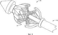
Фиг.3 - местный вид в перспективе дистального участка устройства, изображенного на фиг.2, показанного без оболочки, удерживающего анастомотическое кольцо в задействованном положении.Figure 3 is a partial perspective view of the distal portion of the device depicted in figure 2, shown without a sheath, holding the anastomotic ring in the engaged position.
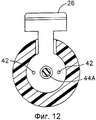
Фиг.4 - вид спереди приведенного в действие анастомотического кольца.Figure 4 is a front view of a powered anastomotic ring.
Фиг.5 - вид в перспективе устройства для наложения анастомотического кольца, изображенного на фиг.1, с задействованным дистальным участком его механизма развертывания кольца.FIG. 5 is a perspective view of a device for applying an anastomotic ring of FIG. 1 with a distal portion of its ring deployment mechanism engaged.
Фиг.6 - вид в перспективе устройства, изображенного на фиг.1, с задействованными дистальным участком и проксимальным участком его механизма развертывания кольца.6 is a perspective view of the device depicted in figure 1, with the distal portion involved and the proximal portion of its ring deployment mechanism.
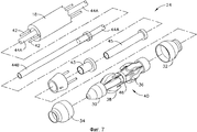
Фиг.7 - вид в перспективе с пространственным разделением деталей механизма развертывания анастомотического кольца устройства, изображенного на фиг.1.Fig.7 is a perspective view with a spatial separation of the details of the deployment mechanism of the anastomotic ring of the device shown in Fig.1.
Фиг.8 - вид в перспективе, в разрезе, с пространственным разделением деталей проксимального участка устройства, изображенного на фиг.1, с удаленной левой половиной корпуса.Fig.8 is a perspective view, in section, with a spatial separation of the details of the proximal portion of the device shown in Fig.1, with the left half of the body removed.
Фиг.9 - местное сечение дистального участка устройства, изображенного на фиг.1, вставленного через анастомотическое отверстие.Fig.9 is a local section of the distal portion of the device shown in Fig.1, inserted through the anastomotic hole.
Фиг.10 - местное сечение дистального участка устройства, изображенного на фиг.1, образующего анастомотическое скрепление между соседними стенками из ткани желудочно-кишечной системы.Figure 10 is a local section of the distal portion of the device depicted in figure 1, forming an anastomotic bond between adjacent walls of tissue of the gastrointestinal system.
Фиг.11 - местное сечение проксимального участка устройства, изображенного на фиг.1.11 is a local section of the proximal section of the device depicted in figure 1.
Фиг.12 - сечение по плоскости 12, показанной на фиг.11.12 is a section along the
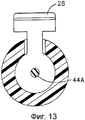
Фиг.13 - сечение по плоскости 13, показанной на фиг.11.Fig.13 is a section along the
ПОДРОБНОЕ ОПИСАНИЕ ВАРИАНТОВ ОСУЩЕСТВЛЕНИЯ ИЗОБРЕТЕНИЯDETAILED DESCRIPTION OF EMBODIMENTS OF THE INVENTION
Если обратиться к чертежам, на которых одинаковыми позициями обозначены одинаковые компоненты на нескольких видах, на фиг.1 представлено устройство 10 для наложения, которое функционально предназначено для развертывания и приведения в действие анастомотического кольцевого устройства (не показанного на фиг.1) изменением в основном цилиндрической формы на форму, обладающую свойствами полой заклепки или кольца, способного к образованию анастомотического скрепления на намеченном месте анастомоза, например, при желудочном шунтировании пациента с патологическим ожирением. На фиг.2 изображено другое устройство 12 для наложения. Очевидно, что устройства 10, 12 для наложения можно использовать множеством способов, включая, но без ограничения, лапароскопию или эндоскопию. Устройство 12 для наложения показано на фиг.2 с анастомотическим кольцом 14 на механизме 16 развертывания. На фиг.2 анастомотическое кольцо 14 показано в сжатом положении в форме цилиндра. На фиг.3 механизм 16 развертывания устройства 12 для наложения перевел анастомотическое кольцо 14 в приведенное в действие положение в форме полой заклепки. Фиг.4 дает увеличенное изображение анастомотического кольца 14 в приведенном в действие положении. Анастомотическое кольцо 14 может содержать материал с памятью формы (SME), например нитинол, только в виде примера, который дополнительно способствует срабатыванию до зацепляющей формы полой заклепки. Специалистам со средним уровнем компетентности в данной области техники будут очевидны другие подходящие материалы для анастомотических колец 14. Примерное анастомотическое кольцо 14 подробно описано в публикации заявки на патент США № US 2003/0032967 изобретателя Парка с соавторами (Park et al.).If we turn to the drawings, in which the same numbers denote the same components in several views, Fig. 1 shows an
Следует понимать, что термины «проксимальный» и «дистальный» в настоящем описании служат для указания положения относительно захвата врачом рукоятки устройства 10 для наложения. Следует также понимать, что для удобства и ясности такие термины, как «правый», «левый», «вертикальный» и «горизонтальный», служат в настоящем описании для указания пространственного положения на чертежах. Однако существует много ориентаций и положений применения хирургических инструментов и упомянутые термины нельзя считать имеющими ограничительный и абсолютный смысл. Кроме того, аспекты изобретения применимы к хирургическим операциям, выполняемым эндоскопическим и лапароскопическим способами, а также к открытой операции или другим операциям. Применение в настоящем описании одного из данных или аналогичных терминов не следует толковать в смысле ограничения применения настоящего изобретения при хирургических операциях только одной категории.It should be understood that the terms "proximal" and "distal" in the present description are used to indicate the position regarding the capture by the doctor of the handle of the
Как показано на фиг.1, устройство 10 для наложения в настоящем примере содержит рукоятку 17, соединенную с удлиненным стержнем 18, имеющим проксимальный конец 20 и дистальный конец 22. Как показано на фиг.1, удлиненный стержень 18 является гибким либо по всей его длине, либо в, по меньшей мере, одном шарнире. Разумеется, стержень 18 может быть, в качестве альтернативы, жестким, упругим, пластичным или может обладать другими свойствами. Дистальный конец 22 стержня 18 содержит механизм 24 развертывания кольца. Механизм 24 развертывания можно задействовать кнопкой или рычагом, расположенным на рукоятке 17. Как показано на фиг.1, рукоятка 17 содержит пару приводных элементов 26, 28. В настоящем примере приводные элементы 26, 28 содержат движки. Функционирование примерных приводных движков 26, 28 описано ниже. Однако следует понимать, что приводные элементы 26, 28 могут принимать множество других форм и выполнять множество других функций.As shown in FIG. 1, the
В настоящем примере механизм 24 развертывания кольца расположен проксимально относительно наконечника 30. Устройство 10 для наложения содержит конструктивный элемент для предотвращения захвата ткани в механизм 24 развертывания, когда устройство 10 для наложения вставляют в место анастомоза или извлекают из него. На фиг.1 показаны проксимальная оболочка 32 и дистальная оболочка 34.In the present example, the
На фиг.7 механизм 24 развертывания кольца в соответствии с настоящим примером представлен на виде в перспективе с пространственным разделением деталей, где показано, как проксимальная оболочка 32 надевается на множество проксимальных пальцев 36 и дистальная оболочка 34 надевается на множество дистальных пальцев 38. Механизм 24 развертывания кольца содержит неподвижный формованный приводной элемент 40. Конечно, формованный приводной элемент 40 может быть выполнен с использованием любого подходящего способа, отличающегося от формования. В настоящем примере формованный приводной элемент 40 содержит проксимальные пальцы 36 и дистальные пальцы 38. Формованный приводной элемент 40 содержит также центральный участок 46, который жестко соединен со средней трубкой 45. Средняя трубка 45 зафиксирована в дистальном конце 22 стержня 18. Проксимальные пальцы 36 соединены с первым приводным движком 26 через тянуще-толкающие тросы 42 стержня 18 (фиг.12). Тянуще-толкающие тросы 42 сообщаются с внешней трубкой 43, которая жестко соединена с проксимальными пальцами 36. Дистальные пальцы 38 соединены со вторым приводным движком 28 через внутренние трубки 44A, 44B стержня 18 (фиг.13). Внутренняя трубка 44A жестко соединена с внутренней трубкой 44B. Каждый из проксимальных пальцев 36 и дистальных пальцев 38 двухшарнирно связан с центральным участком 46 формованного приводного элемента 40. Специалистам со средним уровнем компетентности в данной области техники будут очевидны другие подходящие конфигурации механизма 24 развертывания кольца.7, the
На фиг.8 и 11 показаны примерные компоненты рукоятки 17. В настоящем примере дистальное перемещение первого приводного движка 26 сообщает дистальное смещение проксимальным пальцам 36 через тянуще-толкающиие тросы 42, чем вынуждает проксимальные пальцы 36 срабатывать наружу наподобие зонтика благодаря их шарнирной связи с центральным участком 46. Аналогично, проксимальное перемещение второго приводного движка 28 сообщает проксимальное смещение дистальным пальцам 38 через внутренние трубки 44A, 44B, чем вынуждает дистальные пальцы 38 срабатывать наружу благодаря их шарнирной связи с центральным участком 46. Следовательно, в данном примере дистальное смещение первого приводного движка 26 приводит в действие проксимальный участок анастомотического кольца 14 из сжатого положения в задействованное положение, тогда как проксимальное смещение второго движка 28 приводит в действие дистальный участок анастомотического кольца 14 из сжатого положения в задействованное положение. В другом варианте осуществления рукоятка 17 выполнена в такой конфигурации, что первый приводной движок 26 связан с дистальными пальцами 38, тогда как второй приводной движок 28 связан с проксимальными пальцами 36. Специалистам со средним уровнем компетентности в данной области техники будут очевидны другие конфигурации, подходящие для обеспечения данных связей. В качестве альтернативы, можно использовать любое другое подходящее средство, способ или механизм для приведения в действие анастомотического кольца из сжатого положения в задействованное положение.Figs. 8 and 11 show exemplary components of the
Пальцы 36, 38 выполнены так, чтобы удерживать анастомотическое кольцо зацеплением лепестков 52 до и во время развертывания анастомотического кольца и отпускать лепестки 52 после развертывания анастомотического кольца 14. Проксимальные пальцы 36 и дистальные пальцы 38 в настоящем примере содержат захватные пазы 48, из которых каждый содержит направленный внутрь фиксирующий наконечник 50. Захватные пазы 48 могут способствовать фиксации анастомотического кольца 14, когда данное кольцо находится в сжатом положении, тогда как фиксирующий наконечник 50 может позволять анастомотическому кольцу 14 выходить из зацепления с лепестками 52 анастомотического кольца 14 после того, как данное кольцо развернуто в приведенное в действие положение. Специалистам со средним уровнем компетентности в данной области техники будут очевидны другие подходящие конфигурации пальцев 36, 38.The
Как показано на фиг.7, механизм 24 развертывания кольца содержит зазоры 54 между проксимальными пальцами 36 и между дистальными пальцами 38. Проксимальная оболочка 32 выполнена так, чтобы охватывать проксимальные пальцы 36, и дистальная оболочка 34 выполнена так, чтобы охватывать дистальные пальцы 38, для того, чтобы предотвращать застревание ткани в зазорах 54 во время вставки и извлечения устройства 10 для наложения. Как показано на фиг.5, дистальная оболочка 34 выполнена так, чтобы перемещаться в задействованное положение вместе с дистальными пальцами 38 в ответ на перемещение в проксимальном направлении второго приводного движка 28. Это позволяет дистальной оболочке 34 предотвращать захват ткани в зазоры 54 во время вставки или извлечения устройства 10 для наложения без помех развертыванию анастомотического кольца 14 или необходимости для хирурга затрачивать дополнительное время и усилия на извлечение оболочки. На фиг.6 показаны как проксимальные пальцы 36, так и дистальные пальцы 38, перемещенные в расширенное положение в результате перемещения приводных движков 26, 28.As shown in FIG. 7, the
Проксимальная и дистальная оболочки 32, 34 могут быть прикреплены к проксимальным и дистальным пальцам 36, 38 соответственно связующим материалом, например клеем, механическим крепежом или любым другим подходящим средством или способом. В одном варианте осуществления проксимальная и дистальная оболочки 32, 34 содержат высокоэластичный материал, который расширяется вместе с проксимальными и дистальными пальцами 36, 38 соответственно. В другом варианте осуществления проксимальная и дистальная оболочки 32, 34 выполнены из нитяной оплетки. Даже если нитяной материал и не обладает эластичностью, он может легко расширяться, чем обеспечивает охват зазоров 54 и при этом позволяет пальцам 36, 38 перемещаться в расширенное положение. Специалистам со средним уровнем компетентности в данной области техники будут очевидны другие подходящие материалы и конфигурации оболочек 32, 34.The proximal and
В одном примере функционирования анастомотическое кольцо 14 удерживается на механизме 24 развертывания кольца захватными пазами 48 проксимальных и дистальных пальцев 36, 38. Устройство 10 для наложения вставляют вблизи места анастомоза, где отверстие 56 выполнено в двух соседних желудочно-кишечных проходах 58, 60, как показано на фиг.9. Когда устройство 10 для наложения вставляют, проксимальная и дистальная оболочки 32, 34 выполняют функцию предотвращения захвата ткани в зазоры 54. Конечно, оболочки 32, 34 могут быть полезными для множества других целей.In one operation example, the
Как показано на фиг.10, после того как механизм 24 развертывания кольца вставлен в анастомотическое отверстие, первый и второй приводные движки 26, 28 можно перевести в соответствующие им задействованные положения, что вынуждает пальцы 36, 38 срабатывать наружу. Это может расширить анастомотическое кольцо 14 из его сжатого положения в форме цилиндра в приведенное в действие положение в форме полой заклепки с образованием анастомотического скрепления между стенками из ткани желудочно-кишечной системы. Специалистам со средним уровнем компетентности в данной области техники будут очевидны другие применения и способы приведения в действие устройства 10 для наложения.As shown in FIG. 10, after the
Выше показаны и описаны различные варианты осуществления и принципы изобретения, однако специалисты со средним уровнем компетентности в данной области техники смогут осуществить дополнительные доработки вышеописанных способов и систем посредством соответствующих модификаций без выхода за пределы объема изобретения. Некоторые из упомянутых возможных вариантов осуществления, модификаций и изменений упоминались, а другие очевидны специалистам в данной области техники в свете вышеописанного изложения. Соответственно предполагается, что изобретение должно охватывать все упомянутые варианты осуществления, модификации и изменения, которые могут быть в пределах сущности и объема притязаний прилагаемой формулы изобретения, и, очевидно, не должно ограничиваться деталями конструкции и функционирования, показанными и описанными в спецификации и на чертежах. Специалистам в данной области техники могут быть очевидны дополнительные преимущества.Various embodiments and principles of the invention are shown and described above, however, specialists with an average level of competence in the art will be able to further refine the above methods and systems through appropriate modifications without departing from the scope of the invention. Some of the mentioned possible embodiments, modifications and changes have been mentioned, while others are obvious to those skilled in the art in light of the foregoing. Accordingly, the invention is intended to cover all of the above embodiments, modifications, and changes that may be within the spirit and scope of the appended claims, and obviously should not be limited to the details of construction and operation shown and described in the specification and in the drawings. Those of ordinary skill in the art may appreciate the additional benefits.
Claims (20)
(i) рукоятку;
(ii) механизм развертывания кольца, выполненный с возможностью вмещения анастомотического кольца, при этом механизм развертывания кольца выполнен с возможностью перемещения между незадействованным, по существу, цилиндрическим положением и приведенным в действие положением, образующим полую заклепку;
(iii) приводной механизм для сообщения приводного усилия механизму развертывания кольца;
(iv) удлиненный стержень, соединяющий рукоятку с механизмом развертывания кольца и выполненный с функциональной возможностью передачи приводного усилия от рукоятки к механизму развертывания кольца; и
(v) оболочка, выполненная с возможностью охвата механизма развертывания кольца во время вставки и извлечения инструмента, при этом оболочка выполнена с возможностью перемещения из незадействованного положения в приведенное в действие положение вместе с механизмом развертывания кольца.1. A surgical instrument for implanting an anastomotic ring device, comprising:
(i) a handle;
(ii) a ring deployment mechanism configured to receive an anastomotic ring, wherein the ring deployment mechanism is movable between an unused, substantially cylindrical position and an actuated position forming a hollow rivet;
(iii) a drive mechanism for communicating drive force to the ring deployment mechanism;
(iv) an elongated rod connecting the handle to the ring deployment mechanism and configured to transmit drive force from the handle to the ring deployment mechanism; and
(v) a shell configured to cover the ring deployment mechanism during insertion and removal of the tool, wherein the shell is movable from an unused position to the actuated position along with the ring deployment mechanism.
(i) рукоятку;
(ii) удлиненный стержень, содержащий проксимальный участок и дистальный участок, при этом упомянутый удлиненный стержень прикреплен к упомянутой рукоятке вблизи проксимального участка удлиненного стержня;
(iii) механизм развертывания кольца, содержащий продольную оконечность и центральный участок, расположенный на дистальном участке удлиненного стержня, при этом механизм развертывания кольца выполнен с возможностью вмещения сжатого анастомотического кольца;
(iv) приводной механизм для перемещения продольной оконечности механизма развертывания кольца к центральному участку механизма развертывания кольца для приведения в действие участка анастомотического кольца; и
(v) оболочку, выполненную с возможностью охвата, по меньшей мере, участка продольной оконечности механизма развертывания кольца во время вставки и извлечения инструмента, при этом оболочка выполнена с возможностью перемещения вместе с продольной оконечностью механизма развертывания кольца.13. A surgical tool for implantation of an anastomotic ring, containing:
(i) a handle;
(ii) an elongated rod comprising a proximal portion and a distal portion, wherein said elongated rod is attached to said handle near the proximal portion of the elongated rod;
(iii) a ring deployment mechanism comprising a longitudinal tip and a central portion located on a distal portion of the elongated shaft, wherein the ring deployment mechanism is configured to receive a compressed anastomotic ring;
(iv) a drive mechanism for moving a longitudinal tip of the ring deployment mechanism to a central portion of the ring deployment mechanism to actuate a portion of the anastomotic ring; and
(v) a shell configured to cover at least a portion of a longitudinal tip of a ring deployment mechanism during insertion and removal of a tool, the shell being movable along with a longitudinal tip of a ring deployment mechanism.
(i) стержень, содержащий дистальный конец и проксимальный конец, при этом дистальный конец содержит ось, определяющую продольное и радиальное направления;
(ii) механизм развертывания кольца, расположенный на дистальном конце стержня на оси, при этом механизм развертывания кольца содержит множество элементов, выполненных с возможностью приведения их в движение в радиальном направлении из первого положения во второе положение, при этом первое положение соответствует незадействованному положению анастомотического кольца, причем второе положение соответствует приведенному в действие положению анастомотического кольца;
(iii) приводной механизм, связанный с механизмом развертывания кольца, при этом приводной механизм выполнен с возможностью приведения в движение множества элементов из первого положения во второе положение; и
(iv) по меньшей мере, одну оболочку, охватывающую, по меньшей мере, участок множества элементов, при этом, по меньшей мере, одна оболочка выполнена с возможностью перемещения в радиальном направлении из первого положения во второе положение вместе с соответствующими элементами.16. A tool for implanting an anastomotic ring, while the tool contains:
(i) a rod comprising a distal end and a proximal end, wherein the distal end contains an axis defining longitudinal and radial directions;
(ii) a ring deployment mechanism located at the distal end of the rod on the axis, wherein the ring deployment mechanism comprises a plurality of elements configured to radially move them from a first position to a second position, wherein the first position corresponds to an unused position of the anastomotic ring wherein the second position corresponds to the actuated position of the anastomotic ring;
(iii) a drive mechanism associated with the ring deployment mechanism, wherein the drive mechanism is configured to drive a plurality of elements from a first position to a second position; and
(iv) at least one shell spanning at least a portion of the plurality of elements, wherein at least one shell is configured to radially move from a first position to a second position together with corresponding elements.
Applications Claiming Priority (2)
| Application Number | Priority Date | Filing Date | Title |
|---|---|---|---|
| US11/120,824 US7632285B2 (en) | 2005-05-03 | 2005-05-03 | Sheath for enabling insertion and extraction of anastomotic ring applier |
| US11/120,824 | 2005-05-03 |
Publications (2)
| Publication Number | Publication Date |
|---|---|
| RU2006114818A RU2006114818A (en) | 2007-11-27 |
| RU2428131C2 true RU2428131C2 (en) | 2011-09-10 |
Family
ID=36888587
Family Applications (1)
| Application Number | Title | Priority Date | Filing Date |
|---|---|---|---|
| RU2006114818/14A RU2428131C2 (en) | 2005-05-03 | 2006-05-02 | Envelope for creating possibility for insertion and removal of device for anastomotic ring application |
Country Status (15)
| Country | Link |
|---|---|
| US (1) | US7632285B2 (en) |
| EP (1) | EP1719456B1 (en) |
| JP (1) | JP2006312052A (en) |
| KR (1) | KR20060115600A (en) |
| CN (1) | CN100579472C (en) |
| AT (1) | ATE390085T1 (en) |
| AU (1) | AU2006201715B2 (en) |
| BR (1) | BRPI0601511B8 (en) |
| CA (1) | CA2545795C (en) |
| DE (1) | DE602006000782T2 (en) |
| HK (1) | HK1097171A1 (en) |
| IL (1) | IL175289A0 (en) |
| RU (1) | RU2428131C2 (en) |
| SG (1) | SG126912A1 (en) |
| TW (1) | TWI400058B (en) |
Families Citing this family (4)
| Publication number | Priority date | Publication date | Assignee | Title |
|---|---|---|---|---|
| US20070021759A1 (en) * | 2005-07-22 | 2007-01-25 | Ethicon Endo-Surgery, Inc. | Flexible endoscopic anastomotic ring applier device |
| US20110087252A1 (en) | 2009-10-08 | 2011-04-14 | Wilson-Cook Medical Inc. | Biliary decompression and anastomosis stent |
| CN110868965B (en) * | 2017-05-03 | 2021-12-28 | 波士顿科学国际有限公司 | Medical device with sealing assembly |
| JP6709928B1 (en) * | 2019-03-12 | 2020-06-17 | 功祐 氏平 | Minimally invasive surgical equipment |
Family Cites Families (17)
| Publication number | Priority date | Publication date | Assignee | Title |
|---|---|---|---|---|
| JPH06327683A (en) * | 1993-05-19 | 1994-11-29 | Olympus Optical Co Ltd | Surgical suture instrument |
| US5443477A (en) * | 1994-02-10 | 1995-08-22 | Stentco, Inc. | Apparatus and method for deployment of radially expandable stents by a mechanical linkage |
| US5904697A (en) * | 1995-02-24 | 1999-05-18 | Heartport, Inc. | Devices and methods for performing a vascular anastomosis |
| US5855312A (en) * | 1996-07-25 | 1999-01-05 | Toledano; Haviv | Flexible annular stapler for closed surgery of hollow organs |
| NL1007349C2 (en) * | 1997-10-24 | 1999-04-27 | Suyker Wilhelmus Joseph Leonardus | System for the mechanical production of anastomoses between hollow structures; as well as device and applicator for use therewith. |
| US7018387B2 (en) | 1998-10-22 | 2006-03-28 | Innovative Interventional Technologies B.V. | Mechanical anastomosis system for hollow structures |
| US6428550B1 (en) * | 1999-05-18 | 2002-08-06 | Cardica, Inc. | Sutureless closure and deployment system for connecting blood vessels |
| US6451029B1 (en) * | 1999-08-23 | 2002-09-17 | University Of South Florida | Intestinal stapling device and method |
| JP2002272748A (en) * | 2001-03-14 | 2002-09-24 | Terumo Corp | Extravascular everting device |
| JP4201702B2 (en) * | 2001-06-20 | 2008-12-24 | パーク メディカル リミテッド ライアビリティ カンパニー | Anastomosis device |
| JP4504599B2 (en) * | 2001-07-27 | 2010-07-14 | 治文 加藤 | Anastomosis aid |
| US6726714B2 (en) * | 2001-08-09 | 2004-04-27 | Scimed Life Systems, Inc. | Stent delivery system |
| US20050119682A1 (en) * | 2001-10-30 | 2005-06-02 | Eric Nguyen | Vascular exclusion catheter |
| WO2004098417A1 (en) | 2003-04-16 | 2004-11-18 | Tyco Healthcare Group Lp | Method and apparatus for radical prostatectomy anastomosis including an anchor for engaging a body vessel and deployable sutures |
| US7608086B2 (en) * | 2003-09-30 | 2009-10-27 | Ethicon Endo-Surgery, Inc. | Anastomosis wire ring device |
| US20050070939A1 (en) * | 2003-09-30 | 2005-03-31 | Jean Beaupre | Unfolding anastomosis ring device |
| US7309341B2 (en) | 2003-09-30 | 2007-12-18 | Ethicon Endo-Surgery, Inc. | Single lumen anastomosis applier for self-deploying fastener |
-
2005
- 2005-05-03 US US11/120,824 patent/US7632285B2/en active Active
-
2006
- 2006-04-26 AU AU2006201715A patent/AU2006201715B2/en not_active Ceased
- 2006-04-27 IL IL175289A patent/IL175289A0/en unknown
- 2006-04-27 SG SG200602861A patent/SG126912A1/en unknown
- 2006-05-02 TW TW095115635A patent/TWI400058B/en not_active IP Right Cessation
- 2006-05-02 JP JP2006128518A patent/JP2006312052A/en active Pending
- 2006-05-02 RU RU2006114818/14A patent/RU2428131C2/en not_active IP Right Cessation
- 2006-05-02 EP EP06252335A patent/EP1719456B1/en active Active
- 2006-05-02 CA CA2545795A patent/CA2545795C/en not_active Expired - Fee Related
- 2006-05-02 DE DE602006000782T patent/DE602006000782T2/en active Active
- 2006-05-02 AT AT06252335T patent/ATE390085T1/en not_active IP Right Cessation
- 2006-05-03 KR KR1020060039930A patent/KR20060115600A/en not_active Application Discontinuation
- 2006-05-03 BR BRPI0601511A patent/BRPI0601511B8/en active IP Right Grant
- 2006-05-08 CN CN200610077480A patent/CN100579472C/en active Active
-
2007
- 2007-04-20 HK HK07104183A patent/HK1097171A1/en not_active IP Right Cessation
Also Published As
| Publication number | Publication date |
|---|---|
| AU2006201715B2 (en) | 2012-03-22 |
| AU2006201715A1 (en) | 2006-11-23 |
| DE602006000782D1 (en) | 2008-05-08 |
| HK1097171A1 (en) | 2007-06-22 |
| CN1857176A (en) | 2006-11-08 |
| ATE390085T1 (en) | 2008-04-15 |
| KR20060115600A (en) | 2006-11-09 |
| TW200701932A (en) | 2007-01-16 |
| DE602006000782T2 (en) | 2009-04-30 |
| CA2545795A1 (en) | 2006-11-03 |
| JP2006312052A (en) | 2006-11-16 |
| CA2545795C (en) | 2014-02-11 |
| US7632285B2 (en) | 2009-12-15 |
| RU2006114818A (en) | 2007-11-27 |
| IL175289A0 (en) | 2006-09-05 |
| EP1719456A1 (en) | 2006-11-08 |
| BRPI0601511B8 (en) | 2021-06-22 |
| BRPI0601511B1 (en) | 2018-03-13 |
| US20060253133A1 (en) | 2006-11-09 |
| BRPI0601511A (en) | 2006-12-26 |
| TWI400058B (en) | 2013-07-01 |
| EP1719456B1 (en) | 2008-03-26 |
| SG126912A1 (en) | 2006-11-29 |
| CN100579472C (en) | 2010-01-13 |
Similar Documents
| Publication | Publication Date | Title |
|---|---|---|
| RU2426505C2 (en) | Membrane-free device for installation of anastomosis ring | |
| RU2428132C2 (en) | Surgical instrument for removal of anastomotic ring device | |
| RU2426510C2 (en) | Device for anastomosis ring application set in action by double movement | |
| JP2007029728A (en) | Disposable anastomosis ring applier | |
| RU2428131C2 (en) | Envelope for creating possibility for insertion and removal of device for anastomotic ring application | |
| RU2426508C2 (en) | Flexible anastomosis ring applicator | |
| JP5389319B2 (en) | Flexible endoscopic anastomosis ring applier device | |
| MXPA06004947A (en) | Sheath for enabling insertion and extraction of anastomotic ring applier | |
| MXPA06005163A (en) | Anastomotic ring applier with double motion actuation | |
| MXPA06008304A (en) | Flexible endoscopic anastomotic ring applier device | |
| MXPA06004948A (en) | Surgical instrument for extracting an anastomotic ring device | |
| MXPA06004964A (en) | Sheathless anastomotic ring applier device |
Legal Events
| Date | Code | Title | Description |
|---|---|---|---|
| MM4A | The patent is invalid due to non-payment of fees |
Effective date: 20200503 |