RU2425307C2 - Device for loose material drying - Google Patents
Device for loose material drying Download PDFInfo
- Publication number
- RU2425307C2 RU2425307C2 RU2009136105/06A RU2009136105A RU2425307C2 RU 2425307 C2 RU2425307 C2 RU 2425307C2 RU 2009136105/06 A RU2009136105/06 A RU 2009136105/06A RU 2009136105 A RU2009136105 A RU 2009136105A RU 2425307 C2 RU2425307 C2 RU 2425307C2
- Authority
- RU
- Russia
- Prior art keywords
- drum
- sinusoid
- generatrix
- axis
- section
- Prior art date
Links
- 238000001035 drying Methods 0.000 title claims abstract description 14
- 239000000463 material Substances 0.000 title claims description 13
- 230000000694 effects Effects 0.000 abstract description 4
- 230000006378 damage Effects 0.000 abstract description 3
- 238000000034 method Methods 0.000 abstract description 3
- 239000000126 substance Substances 0.000 abstract description 2
- 239000002245 particle Substances 0.000 description 7
- 238000010586 diagram Methods 0.000 description 2
- 238000004519 manufacturing process Methods 0.000 description 2
- 239000007787 solid Substances 0.000 description 2
- 208000027418 Wounds and injury Diseases 0.000 description 1
- 230000005540 biological transmission Effects 0.000 description 1
- 239000013590 bulk material Substances 0.000 description 1
- 238000010276 construction Methods 0.000 description 1
- 230000008030 elimination Effects 0.000 description 1
- 238000003379 elimination reaction Methods 0.000 description 1
- 238000005265 energy consumption Methods 0.000 description 1
- 230000005484 gravity Effects 0.000 description 1
- 238000010438 heat treatment Methods 0.000 description 1
- 208000014674 injury Diseases 0.000 description 1
- 238000009434 installation Methods 0.000 description 1
- 230000007246 mechanism Effects 0.000 description 1
- 230000035939 shock Effects 0.000 description 1
Images

Landscapes
- Drying Of Solid Materials (AREA)
Abstract
Description
Изобретение относится к сушильной технике и может быть использовано в сельском хозяйстве, пищевой, химической, фармацевтической, строительной и других отраслях промышленности.The invention relates to drying equipment and can be used in agriculture, food, chemical, pharmaceutical, construction and other industries.
Известна барабанная сушилка сыпучих материалов (а.с. СССР №954747 A1, F26B 11/04, 30.08.1982, 3 стр.), которая является наиболее близким техническим решением к данному изобретению по своей сущности. Здесь сушильный барабан состоит из нескольких секций, причем каждая секция выполнена с криволинейной боковой поверхностью. В результате образующая барабана по длине приобретает в целом синусоидальный профиль.Known drum dryer of bulk materials (AS USSR No. 954747 A1, F26B 11/04, 08/30/1982, 3 pp.), Which is the closest technical solution to this invention in essence. Here, the drying drum consists of several sections, and each section is made with a curved side surface. As a result, the drum generatrix acquires a generally sinusoidal profile in length.
Синусоидальный, т.е. «зигзагообразный», профиль образующей барабана, выполненный для обеспечения перемещения частиц с различными скоростями, при прочих равных условиях затормаживает перемещение материала вдоль оси и увеличивает сопротивление перемещению, следовательно, увеличивает энергоемкость технологического процесса и ухудшает осевую турбулизацию потока. В быстроходном режиме он оказывает многократное ударно-сжимающее воздействие на контактный слой материала из-за внутрициклового изменения знака радиуса кривизны стенок. Перпендикулярное ударно-сжимающее воздействие, как известно, травмирует такие сыпучие материалы, как семена сельскохозяйственных культур и лесных растений. Помимо этого, здесь скорости перемещения частиц варьируют путем изменения радиуса кривизны синусоиды, что влечет дополнительные затраты на изготовление секций с различными значениями указанного параметра.Sinusoidal i.e. "Zigzag", the profile of the forming drum, made to ensure the movement of particles with different speeds, ceteris paribus inhibits the movement of material along the axis and increases resistance to movement, therefore, increases the energy consumption of the process and impairs axial flow turbulence. In high-speed mode, it exerts a multiple shock-compressive effect on the contact layer of the material due to the intracyclic change in the sign of the radius of curvature of the walls. Perpendicular shock-compressive action is known to injure bulk materials such as seeds of crops and forest plants. In addition, here the particle velocity varies by changing the radius of curvature of the sinusoid, which entails additional costs for the manufacture of sections with different values of the specified parameter.
Цель изобретения - устранение перечисленных недостатков, а также повышение эффективности работы сушилок.The purpose of the invention is the elimination of these disadvantages, as well as improving the efficiency of dryers.
Поставленная цель достигается тем, что сушильный барабан выполнен сплошным, а синусоидальная его образующая повернута по направлению вращения барабана по винтовой линии с углом ее наклона ![]()
![]()
![]()
![]()
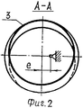
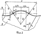
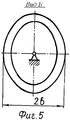
На фиг.1 представлена конструктивно-технологическая схема предлагаемого сушильного устройства, на фиг.2 - сечение А-А на фиг.1, на фиг.3 - профиль образующей барабана с указанием конструктивных параметров, на фиг.4 - схема секционированного по длине сушильного барабана, а на фиг.5 - вид Б на фиг.4.Figure 1 presents the structural and technological diagram of the proposed drying device, figure 2 is a section aa in figure 1, figure 3 is a profile of the generatrix of the drum indicating the design parameters, figure 4 is a diagram of a section along the length of the dryer drum, and figure 5 is a view of B in figure 4.
Устройство для сушки сыпучих материалов (фиг.1) состоит из рамы 1, загрузочного бункера 2, сушильного барабана 3, привода барабана, состоящего из электродвигателя 4 и клиноременной передачи 5, а также воздуховода 6. Горячий воздух во внутрь барабана 3 нагнетается посредством центробежного вентилятора 7. Источниками тепла 8 могут служить известные в технике электрокалориферы или специальные газовые горелки. Для снижения сопротивления материала перемещению и улучшения турбулизации потока в осевом направлении, а также уменьшения травмирования материала синусоидальная образующая 9 (фиг.3) конструктивно повернута по направлению вращения барабана по винтовой линии. На практике значение угла наклона α винта назначается равным 15…20°. Период S синусоиды при заданном значении диаметра D барабана вычисляется по формуле: S=πDtgα. Данный параметр одновременно является и шагом винта. Образующая 9 барабана выполнена в виде синусоиды строго с радиусом кривизны R. Для обеспечения перемещения частиц внутри камеры с различными скоростями барабана 3 закреплен на оси с эксцентриситетом e (фиг.2). В конструктивном исполнении барабан 3 сушильной установки может быть и многосекционным (фиг.4). Профиль образующей в целом - синусоидальный с параметрами S и R, которые одинаковы с параметрами сплошного барабана, указанного на фиг.3. Здесь длина ℓ каждой секции равна периоду S синусоиды, а поперечное сечение выполнено в виде эллипса, большая ось которого наклонена к оси вращения под углом 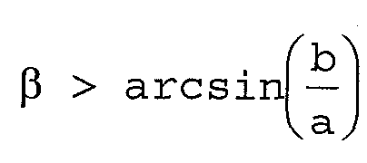
Работает предлагаемое устройство следующим образом. Исходный сыпучий материал из загрузочного бункера 2 (фиг.1) самотеком поступает в сушильный барабан 3, который приводится во вращательное движение через клиноременную передачу 5 электродвигателем 4. Одновременно через воздуховод 6 посредством центробежного вентилятора 7 в сушильную камеру - вовнутрь барабана 3 подается горячий воздух из нагревательного устройства 8. Благодаря выполнению сушильного барабана с синусоидальной образующей, которая повернута по направлению движения по винтовой линии и эксцентричному закреплению его на оси вращения, а также выполнению барабана секционированным по длине, поперечное сечение каждой секции которого выполнено в виде наклоненного к оси вращения эллипса, внутри камеры сушки обеспечивается перемещение частиц в радиальном и осевом направлениях с различными скоростями. Такое конструктивное исполнение барабана резко усиливает турбулизацию потока в осевом направлении, по сравнению с аналогом снижает сопротивление массы перемещению, исключает ударные воздействия на слой материала и обеспечивает вывод высушенного материала из устройства без дополнительных механизмов.The proposed device operates as follows. The source bulk material from the loading hopper 2 (Fig. 1) by gravity enters the
Технико-экономический эффект выразится в значительном повышении эффективности сушилки. Снижается энергоемкость технологического процесса. Уменьшаются затраты, связанные с оптимизацией параметров, поскольку исключается изготовление секций с различными значениями радиуса кривизны стенок. При сушке семян сельскохозяйственных культур и лесных растений уменьшается травмирование материала.The technical and economic effect is expressed in a significant increase in the efficiency of the dryer. The energy intensity of the process is reduced. The costs associated with optimizing the parameters are reduced, since the manufacture of sections with different values of the radius of curvature of the walls is excluded. When drying seeds of agricultural crops and forest plants, the damage to the material is reduced.
Claims (2)
Priority Applications (1)
| Application Number | Priority Date | Filing Date | Title |
|---|---|---|---|
| RU2009136105/06A RU2425307C2 (en) | 2009-09-29 | 2009-09-29 | Device for loose material drying |
Applications Claiming Priority (1)
| Application Number | Priority Date | Filing Date | Title |
|---|---|---|---|
| RU2009136105/06A RU2425307C2 (en) | 2009-09-29 | 2009-09-29 | Device for loose material drying |
Publications (2)
| Publication Number | Publication Date |
|---|---|
| RU2009136105A RU2009136105A (en) | 2011-04-10 |
| RU2425307C2 true RU2425307C2 (en) | 2011-07-27 |
Family
ID=44051833
Family Applications (1)
| Application Number | Title | Priority Date | Filing Date |
|---|---|---|---|
| RU2009136105/06A RU2425307C2 (en) | 2009-09-29 | 2009-09-29 | Device for loose material drying |
Country Status (1)
| Country | Link |
|---|---|
| RU (1) | RU2425307C2 (en) |
Citations (4)
| Publication number | Priority date | Publication date | Assignee | Title |
|---|---|---|---|---|
| SU518607A1 (en) * | 1975-02-14 | 1976-06-25 | Львовский Ордена Ленина Политехнический Институт | Drum dryer for dispersed materials |
| SU542079A1 (en) * | 1975-05-19 | 1977-01-05 | Институт Неорганической Химии И Электрохимии Ан Грузинской Сср | Installation for drying and heating of fine-grained material lumpy |
| SU657222A1 (en) * | 1976-12-06 | 1979-04-15 | Белорусское Отделение Всесоюзного Государственного Научно-Исследовательского И Проектно-Конструкторского Института Энергетики Промышленности | Method of heat treatment of fluent materials and device for effecting same |
| SU954747A1 (en) * | 1981-01-21 | 1982-08-30 | Производственное Объединение "Электрон" | Drum dryer for loose materials |
-
2009
- 2009-09-29 RU RU2009136105/06A patent/RU2425307C2/en not_active IP Right Cessation
Patent Citations (4)
| Publication number | Priority date | Publication date | Assignee | Title |
|---|---|---|---|---|
| SU518607A1 (en) * | 1975-02-14 | 1976-06-25 | Львовский Ордена Ленина Политехнический Институт | Drum dryer for dispersed materials |
| SU542079A1 (en) * | 1975-05-19 | 1977-01-05 | Институт Неорганической Химии И Электрохимии Ан Грузинской Сср | Installation for drying and heating of fine-grained material lumpy |
| SU657222A1 (en) * | 1976-12-06 | 1979-04-15 | Белорусское Отделение Всесоюзного Государственного Научно-Исследовательского И Проектно-Конструкторского Института Энергетики Промышленности | Method of heat treatment of fluent materials and device for effecting same |
| SU954747A1 (en) * | 1981-01-21 | 1982-08-30 | Производственное Объединение "Электрон" | Drum dryer for loose materials |
Also Published As
| Publication number | Publication date |
|---|---|
| RU2009136105A (en) | 2011-04-10 |
Similar Documents
| Publication | Publication Date | Title |
|---|---|---|
| EP3626106A3 (en) | Dryer | |
| US8985313B2 (en) | Screw conveyor | |
| CN107990679A (en) | A kind of dryer of homogeneous heating | |
| CN108700374B (en) | Rotary dryer with multiple drying chambers | |
| RU2425307C2 (en) | Device for loose material drying | |
| RU2620095C1 (en) | Device for grain drying | |
| CN201059850Y (en) | Infrared Dryer | |
| CN207894192U (en) | A kind of dryer of homogeneous heating | |
| CN113349402A (en) | Loosening device for airflow cut-tobacco drier | |
| CA1166443A (en) | Continuously operating hydro-extractor | |
| CN103968645B (en) | A kind of forced fluidized bed formula drying machine | |
| CN107166919B (en) | A fast drying drum dryer | |
| CN105466200B (en) | Hot cyclone drying machine | |
| RU2650011C1 (en) | Conveyor dryer | |
| CN215898851U (en) | Loosening device for airflow cut-tobacco drier | |
| JP2005030650A (en) | Drier | |
| US1339260A (en) | Rotary drier | |
| RU2597275C1 (en) | Method of drying and grinding of plant products and their combinations and dryer for its implementation | |
| CN108332547A (en) | A kind of cylinder separate type drum dryer | |
| CN207040826U (en) | A kind of agrocybe drying unit | |
| RU2386092C2 (en) | Device for implementing bulk material drying method | |
| US2430686A (en) | Gravity flow cotton dryer having opposed throwing members | |
| US907219A (en) | Drier. | |
| US2364274A (en) | Dehydrating apparatus | |
| CN209057475U (en) | A kind of corn seed film forming storehouse |
Legal Events
| Date | Code | Title | Description |
|---|---|---|---|
| MM4A | The patent is invalid due to non-payment of fees |
Effective date: 20110930 |