RU2425268C2 - Device for control of stepless transmission - Google Patents
Device for control of stepless transmission Download PDFInfo
- Publication number
- RU2425268C2 RU2425268C2 RU2008152318/11A RU2008152318A RU2425268C2 RU 2425268 C2 RU2425268 C2 RU 2425268C2 RU 2008152318/11 A RU2008152318/11 A RU 2008152318/11A RU 2008152318 A RU2008152318 A RU 2008152318A RU 2425268 C2 RU2425268 C2 RU 2425268C2
- Authority
- RU
- Russia
- Prior art keywords
- torque
- variator
- gear ratio
- control
- adjusting
- Prior art date
Links
Images

Classifications
-
- F—MECHANICAL ENGINEERING; LIGHTING; HEATING; WEAPONS; BLASTING
- F16—ENGINEERING ELEMENTS AND UNITS; GENERAL MEASURES FOR PRODUCING AND MAINTAINING EFFECTIVE FUNCTIONING OF MACHINES OR INSTALLATIONS; THERMAL INSULATION IN GENERAL
- F16H—GEARING
- F16H61/00—Control functions within control units of change-speed- or reversing-gearings for conveying rotary motion ; Control of exclusively fluid gearing, friction gearing, gearings with endless flexible members or other particular types of gearing
- F16H61/66—Control functions within control units of change-speed- or reversing-gearings for conveying rotary motion ; Control of exclusively fluid gearing, friction gearing, gearings with endless flexible members or other particular types of gearing specially adapted for continuously variable gearings
- F16H61/664—Friction gearings
- F16H61/6648—Friction gearings controlling of shifting being influenced by a signal derived from the engine and the main coupling
-
- F—MECHANICAL ENGINEERING; LIGHTING; HEATING; WEAPONS; BLASTING
- F16—ENGINEERING ELEMENTS AND UNITS; GENERAL MEASURES FOR PRODUCING AND MAINTAINING EFFECTIVE FUNCTIONING OF MACHINES OR INSTALLATIONS; THERMAL INSULATION IN GENERAL
- F16H—GEARING
- F16H15/00—Gearings for conveying rotary motion with variable gear ratio, or for reversing rotary motion, by friction between rotary members
- F16H15/02—Gearings for conveying rotary motion with variable gear ratio, or for reversing rotary motion, by friction between rotary members without members having orbital motion
- F16H15/04—Gearings providing a continuous range of gear ratios
-
- F—MECHANICAL ENGINEERING; LIGHTING; HEATING; WEAPONS; BLASTING
- F16—ENGINEERING ELEMENTS AND UNITS; GENERAL MEASURES FOR PRODUCING AND MAINTAINING EFFECTIVE FUNCTIONING OF MACHINES OR INSTALLATIONS; THERMAL INSULATION IN GENERAL
- F16H—GEARING
- F16H61/00—Control functions within control units of change-speed- or reversing-gearings for conveying rotary motion ; Control of exclusively fluid gearing, friction gearing, gearings with endless flexible members or other particular types of gearing
- F16H61/66—Control functions within control units of change-speed- or reversing-gearings for conveying rotary motion ; Control of exclusively fluid gearing, friction gearing, gearings with endless flexible members or other particular types of gearing specially adapted for continuously variable gearings
- F16H61/664—Friction gearings
-
- F—MECHANICAL ENGINEERING; LIGHTING; HEATING; WEAPONS; BLASTING
- F16—ENGINEERING ELEMENTS AND UNITS; GENERAL MEASURES FOR PRODUCING AND MAINTAINING EFFECTIVE FUNCTIONING OF MACHINES OR INSTALLATIONS; THERMAL INSULATION IN GENERAL
- F16H—GEARING
- F16H63/00—Control outputs from the control unit to change-speed- or reversing-gearings for conveying rotary motion or to other devices than the final output mechanism
- F16H63/02—Final output mechanisms therefor; Actuating means for the final output mechanisms
- F16H63/04—Final output mechanisms therefor; Actuating means for the final output mechanisms a single final output mechanism being moved by a single final actuating mechanism
- F16H63/06—Final output mechanisms therefor; Actuating means for the final output mechanisms a single final output mechanism being moved by a single final actuating mechanism the final output mechanism having an indefinite number of positions
- F16H63/065—Final output mechanisms therefor; Actuating means for the final output mechanisms a single final output mechanism being moved by a single final actuating mechanism the final output mechanism having an indefinite number of positions hydraulic actuating means
-
- F—MECHANICAL ENGINEERING; LIGHTING; HEATING; WEAPONS; BLASTING
- F16—ENGINEERING ELEMENTS AND UNITS; GENERAL MEASURES FOR PRODUCING AND MAINTAINING EFFECTIVE FUNCTIONING OF MACHINES OR INSTALLATIONS; THERMAL INSULATION IN GENERAL
- F16H—GEARING
- F16H61/00—Control functions within control units of change-speed- or reversing-gearings for conveying rotary motion ; Control of exclusively fluid gearing, friction gearing, gearings with endless flexible members or other particular types of gearing
- F16H61/24—Providing feel, e.g. to enable selection
Abstract
Description
Настоящее изобретение относится к управлению бесступенчатой трансмиссией.The present invention relates to a continuously variable transmission control.
Обычная трансмиссия автомобиля с ручной ступенчатой коробкой передач, в типичном случае, имеет приводимое в действие пользователем сцепление между двигателем и коробкой передач, служащее для их сцепления/расцепления. Когда транспортное средство трогается, то есть когда оно начинает движение от состояния покоя, существует неизбежное первоначальное рассогласование скоростей между входом трансмиссии и выходом двигателя, и, допуская проскальзывание сцепления на этом этапе, водитель вызывает приложение вращающего момента к трансмиссии для разгона транспортного средства, не применяя неприемлемой нагрузки к двигателю, которая могла бы вызвать его остановку. В случае с обычными автоматическими ступенчатыми трансмиссиями первоначальное рассогласование скоростей урегулируется преобразователем вращающего момента. Сцепление и преобразователь вращающего момента являются примерами того, что будет называться здесь "стартовыми устройствами".A typical car transmission with a manual speed gearbox typically has a user-driven clutch between the engine and gearbox to engage / disengage them. When the vehicle moves off, that is, when it begins to move from a standstill, there is an inevitable initial mismatch of speeds between the input of the transmission and the output of the engine, and, allowing the clutch to slip at this stage, the driver causes the application of torque to the transmission to accelerate the vehicle without applying an unacceptable load on the engine that could cause it to stop. In the case of conventional automatic speed transmissions, the initial speed mismatch is regulated by a torque converter. The clutch and torque converter are examples of what will be referred to herein as “starting devices”.
В некоторых бесступенчатых трансмиссиях стартовое устройство не требуется. Вместо этого такие бесступенчатые трансмиссии способны обеспечивать бесконечное понижение скорости. То есть посредством регулирования передаточного числа и без физического отсоединения двигателя от выхода трансмиссии они могут достигать состояния, в котором выход трансмиссии неподвижен, в то время как двигатель работает.In some continuously variable transmissions, a starting device is not required. Instead, such continuously variable transmissions are capable of providing an infinite reduction in speed. That is, by adjusting the gear ratio and without physically disconnecting the engine from the transmission output, they can reach a state in which the transmission output is stationary while the engine is running.
Это состояние упоминается как "сцепленное нейтральное состояние". Старт может быть достигнут просто смещением передаточного числа бесступенчатой трансмиссии от сцепленного нейтрального состояния, и нет необходимости в отсоединении трансмиссии от двигателя для остановки транспортного средства.This condition is referred to as a “linked neutral state". The start can be achieved simply by shifting the gear ratio of the continuously variable transmission from the engaged neutral state, and there is no need to disconnect the transmission from the engine to stop the vehicle.
Однако изобретатели обнаружили, что было бы предпочтительно, если такая трансмиссия могла бы быть выполнена так, чтобы она имитировала в некоторых отношениях функциональные возможности ручной трансмиссии, имеющей приводимое в действие пользователем сцепление. Использование сцепления очень знакомо многим водителям. Оно дает стабильную гарантию того, что вращающий момент проскальзывания не будет прилагаться к колесам транспортного средства. Оно также полезно, например, при некоторых маневрах с малой скоростью.However, the inventors have found that it would be preferable if such a transmission could be made so that it imitates in some respects the functionality of a manual transmission having a user-driven clutch. Using the clutch is very familiar to many drivers. It provides a stable guarantee that the slipping torque will not be applied to the wheels of the vehicle. It is also useful, for example, for certain low speed maneuvers.
Следует отметить, что слово "двигатель" используется здесь для краткости для ссылки на любую форму вращательного привода и должно рассматриваться как охватывающее не только двигатели внутреннего сгорания, но также и электродвигатели, двигатели внешнего сгорания и т.д.It should be noted that the word “engine” is used here for brevity to refer to any form of rotary drive and should be considered as encompassing not only internal combustion engines, but also electric motors, external combustion engines, etc.
Слово "вариатор" будет использоваться здесь для ссылки на устройство, которое имеет вращательный вход и вращательный выход и которое передает приводное усилие от одного другому с передаточным числом, которое может непрерывно изменяться. Такое устройство можно обнаружить в любой бесступенчатой трансмиссии. Большинство, если не все, вариаторы имеют некоторую подвижную часть для передачи вращающего момента, которая участвует в передаче приводного усилия, и положение которой соответствует передаточному отношению вариатора. В известном случае с вариатором с тороидальной дорожкой качения и тягой качения ролики служат подвижными частями передачи вращающего момента. Они передают приводное усилие от одной тороидальной утопленной дорожки качения к другой, и их движение вызывает изменение наклона роликов, который связан с изменением приводного передаточного числа вариатора. Сила применяется к подвижной части для передачи вращающего момента для влияния на ее положение и, таким образом, для влияния на приводное передаточное число вариатора. В принципе эта сила могла бы передаваться через некоторое прямое соединение со средством управления пользователя, таким как рычаг или педаль. На практике, за исключением случая с очень легкими транспортными средствами, требуемая сила, которая связана с вращающими моментами, воздействующими на вариатор, оказывается слишком большой для комфортабельного применения пользователем. Достижение сцепленного нейтрального состояния с таким устройством также может быть проблематичным, так как любое незначительное отклонение положения части для передачи вращающего момента от положения, требуемого для сцепленного нейтрального состояния, заставит трансмиссию принимать очень низкое приводное передаточное число, потенциально приводящее к большому "вращающему моменту проскальзывания", хотя и при низкой скорости вращения колеса.The word “variator” will be used here to refer to a device that has a rotational input and a rotational output and which transfers drive force from one to another with a gear ratio that can be continuously changed. Such a device can be found in any continuously variable transmission. Most, if not all, variators have some moving part for transmitting torque, which is involved in the transmission of the drive force, and the position of which corresponds to the gear ratio of the variator. In the known case, with a variator with a toroidal raceway and a thrust, the rollers serve as moving parts of the transmission of torque. They transmit the drive force from one toroidal recessed raceway to another, and their movement causes a change in the inclination of the rollers, which is associated with a change in the drive gear ratio of the variator. The force is applied to the moving part to transmit torque to influence its position and, thus, to influence the drive gear ratio of the variator. In principle, this force could be transmitted through some direct connection to a user's control means, such as a lever or pedal. In practice, except in the case of very light vehicles, the required force, which is associated with the torques acting on the variator, is too large for the user to comfortably use. Achieving an adhered neutral state with such a device can also be problematic, since any slight deviation of the position of the torque transmission part from the position required for the adhered neutral state will cause the transmission to adopt a very low drive gear ratio, potentially leading to a large “slippage torque” , although at low wheel speeds.
Современные бесступенчатые трансмиссии, в типичном случае, основаны на сложных электронных контроллерах для управления двигателем и трансмиссией. Однако на рынке есть потребность в простых физических устройствах для управления бесступенчатыми трансмиссиями. Они были бы, в частности, привлекательны для использования, например, в базовых моделях тракторов.Modern continuously variable transmissions are typically based on sophisticated electronic controllers for controlling the engine and transmission. However, there is a need in the market for simple physical devices to drive continuously variable transmissions. They would be particularly attractive for use, for example, in basic tractor models.
В соответствии с первым объектом настоящего изобретения предложено устройство управления вариатором, причем устройство содержит управляемую пользователем часть для регулирования передаточного числа, средство соединения в рабочем положении части для регулирования передаточного числа с подвижной частью для передачи вращающего момента вариатора, позволяющее пользователю осуществлять управление передаточным отношением вариатора, и средство отключения вращающего момента, приводимое в действие пользователем для отсоединения части для регулирования передаточного числа от подвижной части для передачи вращающего момента.In accordance with a first aspect of the present invention, there is provided a CVT control device, the device comprising a user-controlled part for adjusting the gear ratio, means for connecting, in the operating position, the part for adjusting the gear number with the movable part for transmitting the variator torque, allowing the user to control the variator gear ratio, and torque switching means driven by a user to disconnect part d I control the transmission ratio of the movable part for transmitting torque.
Частью для регулирования передаточного числа может быть, например, педаль или рычаг, приводимые в действие пользователем. Рабочее соединение части для регулирования передаточного числа с частью для передачи вращающего момента предпочтительно таково, что положение части для передачи вращающего момента определяется положением части для регулирования передаточного числа.The part for adjusting the gear ratio may be, for example, a pedal or lever operated by a user. The working connection of the part for regulating the gear ratio with the part for transmitting torque is preferably such that the position of the part for transmitting torque is determined by the position of the part for adjusting the gear ratio.
В соответствии со вторым объектом настоящего изобретения предложено устройство управления вариатором, причем устройство содержит приводимую в действие пользователем часть для регулирования передаточного числа, средство соединения в рабочем положении части для регулирования передаточного числа с подвижной частью для передачи вращающего момента вариатора, позволяющее пользователю осуществлять управление передаточным отношением вариатора, и средство приложения к части для регулирования передаточного числа усилия, которое изменяется в соответствии с силой, испытываемой подвижной частью для передачи вращающего момента.According to a second aspect of the present invention, there is provided a variator control device, the apparatus comprising a user-driven part for adjusting a gear ratio, means for connecting, in a working position, a part for adjusting a gear ratio with a movable part for transmitting a variator torque, allowing the user to control the gear ratio variator, and means of application to the part for regulating the gear ratio of the force, which changes in accordance with the force experienced by the moving part to transmit torque.
Конкретные варианты осуществления настоящего изобретения будут теперь описаны только для примера, со ссылками на прилагаемые чертежи, на которых:Specific embodiments of the present invention will now be described by way of example only, with reference to the accompanying drawings, in which:
фиг.1 - очень упрощенный и схематический вид вариатора, пригодного для использования при осуществлении настоящего изобретения;figure 1 is a very simplified and schematic view of a variator suitable for use in the implementation of the present invention;
фиг.2 - схематический вид бесступенчатой трансмиссии, пригодной для использования при осуществлении настоящего изобретения; иfigure 2 is a schematic view of a continuously variable transmission suitable for use in the implementation of the present invention; and
фиг.3 - схематический вид устройства управления, соответствующего варианту осуществления настоящего изобретения.3 is a schematic view of a control device according to an embodiment of the present invention.
На фиг.1 показан вариатор известного типа с тороидальной дорожкой качения с тягой качения. Настоящее изобретение было разработано в связи с бесступенчатой трансмиссией с использованием этого типа вариатора, который особенно хорошо пригоден для этой цели, но, в принципе, могут использоваться вариаторы других типов.Figure 1 shows a variator of the known type with a toroidal raceway with a rolling thrust. The present invention was developed in connection with a continuously variable transmission using this type of variator, which is particularly well suited for this purpose, but, in principle, other types of variators can be used.
Вариатор 10 включает соосно установленные входную и выходную дорожки 12, 14 качения, смежные поверхности 6, 8 которых имеют полутороидальные выемки и совместно образуют в целом тороидальную полость 16, содержащую подвижную часть для передачи вращающего момента в форме ролика 18. Фактически, существующий на практике вариатор, в типичном случае, имеет два или три таких ролика, разнесенных с интервалами по окружности полости 16. Каждый ролик 18 катится по поверхностям 6, 8 соответствующих дорожек 12, 14 качения и, таким образом, служит для передачи приводного усилия от одной другой. Ролик 18 способен двигаться назад и вперед в направлении по окружности вокруг общей оси 20 дорожек 12, 14 качения. Он также способен прецессировать. То есть, ось ролика способна поворачиваться, изменяя отклонение оси ролика относительно оси диска. В показанном примере эти движения предусмотрены благодаря установке ролика 18 с возможностью вращения в носителе 22, соединенном штоком 24 с поршнем 26 привода 28. Линия 19 от центра поршня 26 к центру ролика 18 составляет ось прецессии, вокруг которой может вращаться весь узел. Прецессия ролика приводит к изменениям радиусов траекторий, проходимых роликом по дорожкам 12, 14 качения, и, следовательно, к изменению передаточного числа привода вариатора.The
Следует отметить, что в этом примере ось 19 прецессии не лежит точно в плоскости, перпендикулярной общей оси 20, но вместо этого наклонена относительно этой плоскости. Угол отклонения обозначен ссылочной позицией СА на чертеже и известен как "угол самоориентации ролика". Когда ролик движется назад и вперед, он следует круговой траектории с центром на общей оси 20. Кроме того, воздействие дорожек 12, 14 качения на ролик создает правящий момент, который имеет тенденцию сохранять его с таким отклонением, чтобы ось ролика пересекала общую ось 20. Это пересечение осей может поддерживаться, несмотря на перемещение ролика назад и вперед по его круговой траектории, на основании угла самоориентации ролика. Когда ролик перемещается по его траектории, он также направляется действием дорожек качения, вызывающих его прецессию таким образом, чтобы сохранять пересечение осей. В результате положение ролика на его траектории соответствует определенному отклонению ролика и, следовательно, определенному приводному передаточному числу вариатора.It should be noted that in this example, the
Привод 28 принимает противодействующие давления рабочей жидкости по линиям 30, 32. Сила, таким образом созданная приводом 28, вызывает движение ролика по его круговой траектории вокруг общей оси 20, и в состоянии равновесия он балансируется силами, прилагаемыми к ролику дорожками 12, 14 качения. Сила, прилагаемая дорожками качения, пропорциональна сумме вращающих моментов, прилагаемых извне к дорожкам качения вариатора. Эта сумма, представляющая собой сумму входного вращающего момента вариатора и выходного вращающего момента вариатора, является эффективным крутящим моментом, который должен воздействовать на крепежные средства вариатора и упоминается как реактивный момент.The
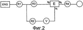
На фиг.2 двигатель представлен блоком ENG, вариатор кружком V и планетарная параллельная передача блоком Е. Вход вариатора соединен с двигателем зубчатыми передачами R1, R2. Его выход соединен с первым входным валом S1 планетарной параллельной передачей Е. Второй входной вал S2 планетарной параллельной передачи Е соединен через передачи R1, R3 с постоянным передаточным отношением с двигателем. Выходной вал S3 планетарной параллельной передачи Е соединен через зубчатую передачу R4 с пунктом использования мощности, в данном случае, колесами W автомобиля. Действие и конструкция планетарной трансмиссии хорошо известны. Скорость выходного вала S3 может быть выражена как функция скоростей входных валов S1, S2. При определенном приводном передаточном числе вариатора скорости валов S1 и S2 уравновешивают друг друга, и выходная скорость вала S3 является нулевой независимо от скорости двигателя. Это представляет собой "сцепленное нейтральное" состояние, упомянутое выше. Приводные передаточные числа вариатора к одной стороне в сцепленном нейтральном состоянии для вала S3 выдают вращение в одном направлении, и приводные передаточные числа вариатора к другой стороне в сцепленном нейтральном состоянии для вала S3 выдают вращение в противоположном направлении.In Fig.2, the engine is represented by the ENG block, the variator is in a circle V and the planetary gear is in parallel with the E. The CVT input is connected to the engine by gears R1, R2. Its output is connected to the first input shaft S1 by planetary parallel gear E. The second input shaft S2 of planetary parallel gear E is connected via gears R1, R3 with a constant gear ratio to the engine. The output shaft S3 of the planetary parallel gear E is connected via a gear transmission R4 to a power use point, in this case, the car wheels W. The action and design of a planetary transmission is well known. The speed of the output shaft S3 can be expressed as a function of the speeds of the input shafts S1, S2. With a certain gear ratio of the variator, the speeds of the shafts S1 and S2 balance each other, and the output speed of the shaft S3 is zero regardless of the engine speed. This is the “linked neutral” state mentioned above. The gear ratios of the variator to one side in the engaged neutral state for the shaft S3 produce rotation in one direction, and the gear ratios of the variator to the other side in the engaged neutral state for the shaft S3 produce rotation in the opposite direction.
Таким образом, посредством регулирования приводного передаточного числа вариатора можно переходить от движения вперед через сцепленное нейтральное состояние к движению назад.Thus, by adjusting the drive gear ratio of the variator, it is possible to switch from moving forward through an adhered neutral state to moving backward.
Устройство управления, соответствующее настоящему изобретению, будет теперь описано со ссылками на фиг.3, где привод управления вариатором и поршень опять обозначены ссылочными позициями 28 и 26, соответственно. Устройство служит для управления гидравлическими давлениями, прилагаемыми к приводу, который, в свою очередь, управляет передаточным отношением вариатора.The control device of the present invention will now be described with reference to FIG. 3, where the variator control drive and piston are again indicated by 28 and 26, respectively. The device is used to control the hydraulic pressures applied to the actuator, which, in turn, controls the gear ratio of the variator.
Приводимая в действие пользователем часть для регулирования передаточного числа обозначена ссылочной позицией 50 на фигуре. Часть для регулирования передаточного числа в рабочем положении соединена с роликами вариатора. Пользователь перемещает эту часть для регулирования передаточного числа, принятого вариатором и, следовательно, трансмиссией в целом. Передаточное отношение вариатора является функцией положения части для регулирования передаточного числа. Часть для регулирования передаточного числа может перемещаться в непрерывном диапазоне, обозначенном стрелками на чертеже, от положения максимального передаточного числа для движения вперед через сцепленное нейтральное положение к положению максимального передаточного числа для движения назад. Диапазоны передаточных отношений вперед и назад, в типичном случае, будут разными, давая более высокие скорости движения вперед, чем назад. Часть для регулирования передаточного числа в этом варианте конструкции сформирована ручным рычагом. В альтернативном варианте ею может быть педаль. Механизмы педали известны, причем водитель, используя подушечки и пятку стопы, может качать педаль в обе стороны от нейтрального положения. Они были бы хорошо пригодны в этом контексте, но альтернативным вариантом может быть предоставление водителю двух педалей, то есть одну для движения вперед и одну для движения назад.The user-driven gear ratio adjusting portion is indicated at 50 in the figure. The part for adjusting the gear ratio in the working position is connected to the variator rollers. The user moves this part to control the gear ratio adopted by the variator and, therefore, the transmission as a whole. The gear ratio of the variator is a function of the position of the part for adjusting the gear ratio. The gear ratio adjusting part can move in a continuous range, indicated by arrows in the drawing, from the maximum gear ratio for forward movement through the engaged neutral position to the maximum gear ratio for reverse movement. The ranges of gear ratios forward and backward, in a typical case, will be different, giving higher forward speeds than backward. The gear ratio control part in this embodiment is formed by a hand lever. Alternatively, it may be a pedal. The pedal mechanisms are known, and the driver, using the pads and the heel of the foot, can swing the pedal to both sides of the neutral position. They would be well suited in this context, but an alternative would be to provide the driver with two pedals, that is, one for moving forward and one for moving backward.
Средство, использованное для рабочего соединения части для регулирования передаточного числа с роликами вариатора, можно видеть на чертеже, и оно является гидромеханическим. Коротко, в числе его основных компонентов используется компаратор 52, который принимает и сравнивает (a) положение части для регулирования передаточного числа и (b) положение роликов вариатора и в результате модулирует силу для перемещения роликов в положение, указанное пользователем при помощи части для регулирования передаточного числа. Эта сила создается при помощи средства 54 регулирования гидравлического давления, подающего давление жидкости приводу 28. Средство также служит для приложения силы обратной связи, показательной для вращающего момента вариатора, к части для регулирования передаточного числа для снабжения пользователя информацией о вращающем моменте. Это осуществляется при помощи средства 56 силовой обратной связи. Пользователь снабжается средством 58 управления отключением вращающего момента, которое, действуя через средство 60 отключения вращающего момента, служит для рабочего отсоединения части 50 для регулирования передаточного числа от вариатора и, таким образом, для обнуления реактивного момента вариатора, таким образом создавая функциональные возможности, которые до некоторой степени подобны обеспечиваемым сцеплением в обычной ручной трансмиссии.The tool used for the working connection of the part for adjusting the gear ratio with the variator rollers can be seen in the drawing, and it is hydromechanical. Briefly, among its main components, a comparator 52 is used, which receives and compares (a) the position of the part for adjusting the gear ratio and (b) the position of the variator rollers and as a result modulates the force to move the rollers to the position indicated by the user with the part for regulating the gear numbers. This force is generated by means of a hydraulic pressure control means 54 supplying fluid pressure to the
Эти объекты будут теперь описаны более подробно, начиная со средства 52 компаратора.These objects will now be described in more detail, starting with means 52 of the comparator.
В данном варианте осуществления изобретения в компараторе используется система механических рычагов. Рычаг, формирующий часть 50 для регулирования передаточного числа, поворачивается вокруг фиксированной точки 62 опоры и проходит за точку опоры к шарнирному соединению со связующей частью 64, которая, в свою очередь, имеет первое шарнирное соединение 65 компаратора с тягой 66 компаратора. Следовательно, перемещение части 50 для регулирования передаточного числа перемещает первое соединение 65 тяги компаратора.In this embodiment, the comparator uses a mechanical lever system. The lever forming the gear ratio adjusting portion 50 rotates around a fixed fulcrum 62 and extends beyond the fulcrum to a swivel with a connecting portion 64, which, in turn, has a first swivel 65 of the comparator with the comparator link 66. Therefore, moving the gear ratio adjusting portion 50 moves the first comparator link connection 65.
Поршень 26 в данном варианте конструкции соединен с тягой компаратора при помощи тросика 68 и средства 70 момента обратной связи (функция средства 70 момента обратной связи будет описана ниже). Средство момента обратной связи шарнирно соединено с тягой 66 компаратора через второе соединение 72 компаратора. Следовательно, положение второго соединения компаратора соответствует положению ролика вариатора и, таким образом, передаточному отношению вариатора.In this embodiment, the
Между первым и вторым соединениями 65, 72 компаратора тяга 66 компаратора имеет контрольное соединение 74 с тягой 76 управления клапаном, в свою очередь, ведущей к клапану 78 регулирования давления.Between the first and second comparator connections 65, 72, the comparator rod 66 has a control connection 74 with a valve control rod 76, which in turn leads to a pressure control valve 78.
Действие рычажного средства состоит в установке состояния клапана 78 регулирования давления на основе сравнения передаточного числа вариатора с положением части 50 для регулирования передаточного числа.The action of the lever means is to set the state of the pressure control valve 78 based on a comparison of the gear ratio of the variator with the position of the gear ratio adjusting part 50.
Клапан 78 регулирования давления формирует часть средства 54 регулирования давления. Он имеет отверстие, которое принимает жидкость под давлением, поступающую по линии 80 для жидкости от насоса 82. Насос 82 всасывает из картера 84 и снабжен предохранительным клапаном 86. Клапан регулирования давления имеет отверстия, сообщающиеся с двумя подающими трубопроводами S1, S2, приспособленными для подачи жидкости, соответственно, к противоположным сторонам поршня 26 вариатора. Давление в линии S1 перемещает поршень 26 в одном направлении. Давление в линии S2 перемещает его в другом направлении. Клапан 78 регулирования давления является пропорциональным клапаном с тремя состояниями. В одном он подает жидкость под давлением от насоса в линию S1. В другом, он подает жидкость от насоса в линию S2. В третьем, промежуточном состоянии он изолирует линии S1 и S2 от давления насоса.The pressure control valve 78 forms part of the pressure control means 54. It has an opening that receives fluid under pressure from the fluid line 82 from the pump 82. The pump 82 is sucked from the crankcase 84 and is equipped with a safety valve 86. The pressure control valve has openings in communication with the two supply pipelines S1, S2, adapted for supplying fluid, respectively, to opposite sides of the
Рассмотрим, что происходит, когда в системе, бывшей в состоянии равновесия, пользователь перемещает часть 50 для регулирования передаточного числа. Это производит рассогласование между положением управляющей части и передаточным отношением вариатора. Первое соединение 65 компаратора перемещается. В этом примере предположим, что это перемещение влево при взгляде на фигуру. Контрольное соединение 74, таким образом, также перемещается влево, заставляя клапан регулирования давления принять его второе состояние, подавая давление насоса в линию S2 и сливая из S1 в картер. Результирующее давление на поршень 26 увлекает его влево, как видно на фигуре, перемещая поршень и изменяя передаточное отношение вариатора. Это движение передается через тросовое соединение 68, перемещая второе соединение компаратора вправо. Когда это движение вправо второго соединения компаратора достаточно для уравновешивания движения влево первого соединения компаратора, клапан 78 регулирования давления возвращается к его третьему положению для сохранения давления поршня и положения.Consider what happens when, in an equilibrium system, the user moves part 50 to adjust the gear ratio. This produces a mismatch between the position of the control part and the gear ratio of the variator. The first comparator connection 65 moves. In this example, suppose this is a left shift when looking at a shape. The test connection 74 thus also moves to the left, causing the pressure control valve to assume its second state, supplying pump pressure to line S2 and draining from S1 to the crankcase. The resulting pressure on the
Фактически, это сервосистема для управления положением ролика с использованием гидравлического привода и механической обратной связи по положению.In fact, it is a servo system for controlling the position of the roller using a hydraulic actuator and mechanical position feedback.
Пользователь, в принципе, способен затребовать любое отношение в любой момент, и это может создавать трудности. Очень быстрое изменение требуемого передаточного отношения может привески, например, к чрезмерному вращающему моменту колеса. Система была разработана в связи с сельскохозяйственными транспортными средствами, имеющими низкие передаточные числа и высокие вращающие моменты двигателя, и в этом контексте вполне возможно из-за неосторожности пользователя вызвать движение транспортного средства на двух колесах, с его рулевыми колесами в воздухе. Для снабжения пользователя информацией о вращающих моментах, создаваемых в трансмиссии, средство 56 силовой обратной связи прилагает к части для регулирования передаточного числа пользователя силу, которая соответствует вращающему моменту. Как показано на фиг.3, средство силовой обратной связи содержит средство двойного действия поршня 88 и цилиндра 90. К противоположным сторонам поршня прилагаются давления, принятые прямо из соответствующих подающих трубопроводов S1, S2. Сила, таким образом прилагаемая к части для регулирования передаточного числа, таким образом, пропорциональна силе, прилагаемой к роликам вариатора поршнем 26 вариатора, хотя посредством пригодного подбора площадей поршня обеспечивается то, что первая меньше, чем последняя. Как описано выше, сила, воздействующая на ролики вариатора, пропорциональна реактивному моменту вариатора, в результате чего пользователь испытывает силу обратной связи, которая прямо связана с реактивным моментом.The user, in principle, is able to request any relationship at any time, and this can create difficulties. A very rapid change in the required gear ratio can result in, for example, excessive wheel torque. The system was developed in connection with agricultural vehicles having low gear ratios and high engine torques, and in this context it is quite possible, due to the carelessness of the user, to cause the vehicle to move on two wheels, with its steering wheels in the air. To provide the user with information about the torques created in the transmission, the force feedback means 56 applies a force corresponding to the torque to the part for adjusting the user's gear ratio. As shown in FIG. 3, the force feedback means comprises a dual-action piston 88 and a cylinder 90. Pressure is applied to opposite sides of the piston directly from respective supply pipelines S1, S2. The force thus applied to the gear ratio adjusting part is thus proportional to the force applied to the variator rollers by the
Обращаясь теперь к средству 58 управления отключением вращающего момента, отметим, что оно может быть, например, ручным рычагом или ножной педалью. При помощи средства 58 управления водитель способен установить на ноль силу, прилагаемую к роликам вариатора. Таким образом, реактивный момент вариатора аналогично устанавливается на ноль, и вариатор становится неспособным поддерживать выходной вращающий момент для привода колес транспортного средства. Эффект является родственным разъединению в обычной ручной трансмиссии в том, что он предотвращает приложение трансмиссией вращающего момента к колесам транспортного средства, но это достигается без какого-либо физического отсоединения двигателя от колес. Вместо этого он основан на рабочем отсоединении роликов вариатора от части 50 для регулирования передаточного числа. Часть 58 для управления отключением вращающего момента воздействует на средство 60 отключения вращающего момента, сформированное в этом варианте осуществления изобретения как клапан отключения вращающего момента, ведущий от одной линии S1 подачи жидкости к другой S2. Когда он открыт, клапан создает путь для уравнивания давлений в подающих трубопроводах. При небольшой или при отсутствии разности давлений на уровне поршня существенная сила не прилагается к роликам вариатора, и, таким образом существенный реактивный момент не может поддерживаться. Закрытие клапана 60 отключения вращающего момента восстанавливает реактивный момент. Клапан 60 представляет собой пропорциональный клапан, и пользователь может регулировать степень его открывания.Turning now to the means 58 control off the torque, we note that it can be, for example, a manual lever or foot pedal. Using the control means 58, the driver is able to set to zero the force exerted on the variator rollers. Thus, the variator reactive moment is likewise set to zero, and the variator becomes unable to maintain the output torque for driving the wheels of the vehicle. The effect is akin to separation in a conventional manual transmission in that it prevents the transmission of torque from applying to the wheels of the vehicle, but this is achieved without any physical disconnection of the engine from the wheels. Instead, it is based on the working disconnection of the variator rollers from part 50 for adjusting the gear ratio. The torque-off control part 58 acts on the torque-off means 60 formed in this embodiment as a torque-off valve leading from one fluid supply line S1 to another S2. When it is open, the valve provides a way to equalize the pressures in the supply lines. With little or no pressure difference at the piston level, a substantial force is not applied to the variator rollers, and thus, a substantial reaction torque cannot be maintained. Closing the torque shutoff valve 60 restores the reactive moment. The valve 60 is a proportional valve, and the user can adjust the degree of its opening.
Средство управления отключением вращающего момента может использоваться аналогично типу стартового устройства, описанного выше, посредством сначала установки части 50 для регулирования передаточного числа для задания движения вперед или назад и затем прогрессивного закрывания клапана 60 отключения вращающего момента для доведения передаточного числа управляемым образом до требуемой величины, вызывая ускорение транспортного средства от состояния покоя. Средство управления отключением вращающего момента может использоваться для плавного медленного движения транспортного средства к желательному положению, как при парковке. В этом случае оно служит для ограничения вращающего момента колеса снова очень подобно обычному сцеплению. Средство управления отключением вращающего момента может также использоваться для отключения любого вращающего момента проскальзывания, например, когда транспортное средство припарковано с работающим двигателем. Однако следует отметить, что пользователь может также управлять трансмиссией без использования этого средства управления. Например, он/она может переключать от движения вперед на движение назад и наоборот с использованием только части 50 для регулирования передаточного числа.The torque off control means can be used similarly to the type of starting device described above, by first setting the gear ratio adjusting part 50 to set the forward or backward movement and then progressively closing the torque shutoff valve 60 to bring the gear ratio in a controlled manner to the required value, causing acceleration of the vehicle from a state of rest. The torque off control can be used to smoothly move the vehicle slowly to the desired position, as in parking. In this case, it serves to limit the torque of the wheel again very much like a conventional clutch. The torque shutdown control can also be used to shut off any slippage torque, for example when the vehicle is parked with the engine running. However, it should be noted that the user can also control the transmission without using this control. For example, he / she can switch from forward to reverse and vice versa using only part 50 to control the gear ratio.
Необходимо также описать средство 70 вращающего момента обратной связи. Оно служит для изменения передаточного отношения вариатора на основе реактивного момента. Оно содержит цилиндр 91, который может двигаться при помощи тросового соединения 68 и который содержит поршень 92, соединенный связующей частью 94 со вторым соединением 72 компаратора. Внутри цилиндра 91 расположены пружины с обеих сторон поршня 92, смещая его к определенному положению. Силы, прилагаемые к поршню при управлении клапаном 78 регулирования давления, не являются большими, и пружины достаточно жесткие, благодаря чему перемещение поршня 92 в его цилиндре, создаваемое этими силами, небольшое или отсутствует совсем. Однако поршень также подвергается воздействию через отсечной клапан 96 давлений в линиях S1/S2. В результате достаточный реактивный момент и, соответственно, достаточная разность давлений в линиях S1 и S2 заставляет поршень двигаться с противодействием пружинам, изменяя действительную длину соединения от троса 68 до тяги 66 компаратора. Результатом является изменение передаточного отношения вариатора таким образом, чтобы понижать реактивный момент, придавая системе некоторую податливость и предохранение от чрезмерного вращающего момента. Отсечной клапан устраняет эту возможность, изолируя средство вращающего момента обратной связи от давлений в линиях S1/S2, когда оно не требуется.It is also necessary to describe the feedback torque means 70. It serves to change the gear ratio of the variator based on the reactive moment. It comprises a cylinder 91, which can be moved by cable connection 68 and which includes a piston 92 connected by a connecting portion 94 to a second comparator connection 72. Inside the cylinder 91, springs are located on both sides of the piston 92, displacing it to a certain position. The forces applied to the piston when controlling the pressure control valve 78 are not large, and the springs are quite rigid, so that the movement of the piston 92 in its cylinder created by these forces is small or absent. However, the piston is also exposed through the shut-off valve 96 pressure in the lines S1 / S2. As a result, a sufficient reactive moment and, accordingly, a sufficient pressure difference in the lines S1 and S2 causes the piston to move against the springs, changing the actual length of the connection from the cable 68 to the thrust 66 of the comparator. The result is a change in the gear ratio of the variator in such a way as to lower the reactive moment, giving the system some flexibility and protection against excessive torque. The shut-off valve eliminates this possibility by isolating the feedback torque means from the pressures in lines S1 / S2 when it is not needed.
Ссылочными позициями 98 и 100 на фиг.3 обозначены гидравлические амортизаторы. Их функцией является гашение нежелательного колебательного поведения вариатора посредством создания некоторого сопротивления потоку в поршень 26 и из него. Ссылочной позицией 102 обозначен перепускной клапан для реверсирования давлений, прилагаемых к вариатору для выхода за установленные пределы.Reference numerals 98 and 100 in FIG. 3 indicate hydraulic shock absorbers. Their function is to quench the undesired oscillatory behavior of the variator by creating some resistance to flow into and out of the
Описанный выше вариант конструкции служит примером только возможного варианта осуществления настоящего изобретения. Возможны многие другие способы осуществления изобретения. Например, рычажное средство, используемое для сравнения положения ролика и требуемого передаточного отношения, может быть заменено клапаном известного типа, в котором золотник и втулка могут перемещаться роликами и частью для регулирования передаточного числа.The embodiment described above is an example of only a possible embodiment of the present invention. Many other methods of carrying out the invention are possible. For example, the lever means used to compare the position of the roller and the desired gear ratio can be replaced by a valve of a known type in which the spool and sleeve can be moved by rollers and part for adjusting the gear ratio.
Claims (17)
Applications Claiming Priority (2)
| Application Number | Priority Date | Filing Date | Title |
|---|---|---|---|
| GB0611265.0 | 2006-06-08 | ||
| GBGB0611265.0A GB0611265D0 (en) | 2006-06-08 | 2006-06-08 | Arrangement for control of a continuously variable transmission |
Publications (2)
| Publication Number | Publication Date |
|---|---|
| RU2008152318A RU2008152318A (en) | 2010-07-20 |
| RU2425268C2 true RU2425268C2 (en) | 2011-07-27 |
Family
ID=36745444
Family Applications (1)
| Application Number | Title | Priority Date | Filing Date |
|---|---|---|---|
| RU2008152318/11A RU2425268C2 (en) | 2006-06-08 | 2007-05-11 | Device for control of stepless transmission |
Country Status (14)
| Country | Link |
|---|---|
| US (1) | US8282525B2 (en) |
| EP (1) | EP2024667B1 (en) |
| JP (1) | JP5249930B2 (en) |
| KR (1) | KR101433752B1 (en) |
| CN (1) | CN101490442B (en) |
| AT (1) | ATE474162T1 (en) |
| BR (2) | BRPI0712137B1 (en) |
| CA (1) | CA2654651C (en) |
| DE (1) | DE602007007760D1 (en) |
| GB (1) | GB0611265D0 (en) |
| MX (1) | MX2008015651A (en) |
| RU (1) | RU2425268C2 (en) |
| WO (1) | WO2007141564A2 (en) |
| ZA (1) | ZA200900026B (en) |
Families Citing this family (4)
| Publication number | Priority date | Publication date | Assignee | Title |
|---|---|---|---|---|
| GB0703353D0 (en) * | 2007-02-21 | 2007-03-28 | Torotrak Dev Ltd | Continuously variable transmission |
| US8613681B2 (en) * | 2009-11-19 | 2013-12-24 | GM Global Technology Operations LLC | Transmission hydraulic control system having clutch compensator feed override |
| KR20130141636A (en) * | 2010-12-15 | 2013-12-26 | 알리손 트랜스미션, 인크. | Variator multiplex valve scheme for a torroidal traction drive transmission |
| JP7225914B2 (en) * | 2019-02-28 | 2023-02-21 | ブラザー工業株式会社 | image forming device |
Family Cites Families (16)
| Publication number | Priority date | Publication date | Assignee | Title |
|---|---|---|---|---|
| GB220331A (en) | 1923-08-10 | 1925-05-07 | Richard Erban | Improvements in and relating to variable-speed gearing |
| US1861303A (en) * | 1930-10-25 | 1932-05-31 | Yarman Grover R De | Friction drive for feed grinder drags |
| GB415076A (en) * | 1932-03-04 | 1934-08-16 | Oloudsley Engineering Company | Improvements in or relating to variable speed power transmission mechanism |
| US3561281A (en) * | 1968-09-06 | 1971-02-09 | Thomas Wilfert | Safety control lever |
| GB1367525A (en) | 1971-12-08 | 1974-09-18 | Gkn Transmissions Ltd | Variable ratio traction drive |
| GB1494128A (en) | 1974-04-06 | 1977-12-07 | Papadimitriou Ioannis | Transmission system |
| US4434676A (en) * | 1982-03-22 | 1984-03-06 | Excelermatic Inc. | Traction roller transmission with mechanical transmission ratio control |
| US4554841A (en) * | 1983-11-04 | 1985-11-26 | Nippon Seiko Kabushiki Kaisha | Speed control device of a toric type infinitely variable transmission |
| GB2177765B (en) | 1985-06-15 | 1989-11-22 | Robert Bishop | Improvements relating to automatic transmission system |
| IT1203524B (en) * | 1986-01-14 | 1989-02-15 | Fiat Auto Spa | MANUALLY OPERATED CONTROL DEVICE FOR A VEHICLE SPEED CHANGE INCLUDING A VARIATOR |
| JPH0749824B2 (en) * | 1986-03-06 | 1995-05-31 | 本田技研工業株式会社 | Shift control method for continuously variable transmission for vehicle |
| US5230669A (en) * | 1989-01-30 | 1993-07-27 | Tervola Pentti J | Stepless transmission with disconnectable neutral seeking mechanism |
| US5230699A (en) * | 1992-02-18 | 1993-07-27 | Grasinger John E | Phalanx splint |
| GB2312257A (en) | 1996-04-19 | 1997-10-22 | Torotrak Dev Ltd | Toroidal race variator control system varies end loading according to net pres sure |
| JP2001235014A (en) * | 2000-02-23 | 2001-08-31 | Mazda Motor Corp | Gear ratio control device for toroidal continuously variable transmission |
| JP2005003193A (en) * | 2003-05-16 | 2005-01-06 | Toyota Motor Corp | Controller of lockup clutch for vehicle |
-
2006
- 2006-06-08 GB GBGB0611265.0A patent/GB0611265D0/en not_active Ceased
-
2007
- 2007-05-11 BR BRPI0712137A patent/BRPI0712137B1/en active IP Right Grant
- 2007-05-11 DE DE602007007760T patent/DE602007007760D1/en active Active
- 2007-05-11 BR BR122018073647-0A patent/BR122018073647B1/en active IP Right Grant
- 2007-05-11 RU RU2008152318/11A patent/RU2425268C2/en active
- 2007-05-11 US US12/308,199 patent/US8282525B2/en not_active Expired - Fee Related
- 2007-05-11 KR KR1020087032093A patent/KR101433752B1/en active IP Right Grant
- 2007-05-11 CN CN200780027022.5A patent/CN101490442B/en active Active
- 2007-05-11 MX MX2008015651A patent/MX2008015651A/en active IP Right Grant
- 2007-05-11 WO PCT/GB2007/050258 patent/WO2007141564A2/en active Application Filing
- 2007-05-11 ZA ZA200900026A patent/ZA200900026B/en unknown
- 2007-05-11 EP EP07733679A patent/EP2024667B1/en active Active
- 2007-05-11 JP JP2009513770A patent/JP5249930B2/en active Active
- 2007-05-11 CA CA2654651A patent/CA2654651C/en active Active
- 2007-05-11 AT AT07733679T patent/ATE474162T1/en not_active IP Right Cessation
Also Published As
| Publication number | Publication date |
|---|---|
| BRPI0712137B1 (en) | 2019-02-05 |
| EP2024667A2 (en) | 2009-02-18 |
| CN101490442A (en) | 2009-07-22 |
| MX2008015651A (en) | 2009-01-09 |
| US20090318259A1 (en) | 2009-12-24 |
| RU2008152318A (en) | 2010-07-20 |
| CA2654651C (en) | 2015-02-17 |
| BR122018073647B1 (en) | 2019-04-16 |
| CN101490442B (en) | 2014-12-10 |
| CA2654651A1 (en) | 2007-12-13 |
| EP2024667B1 (en) | 2010-07-14 |
| US8282525B2 (en) | 2012-10-09 |
| GB0611265D0 (en) | 2006-07-19 |
| WO2007141564A3 (en) | 2008-03-06 |
| JP2009540231A (en) | 2009-11-19 |
| JP5249930B2 (en) | 2013-07-31 |
| DE602007007760D1 (en) | 2010-08-26 |
| KR20090018681A (en) | 2009-02-20 |
| WO2007141564A2 (en) | 2007-12-13 |
| BRPI0712137A2 (en) | 2012-01-10 |
| ZA200900026B (en) | 2010-03-31 |
| ATE474162T1 (en) | 2010-07-15 |
| KR101433752B1 (en) | 2014-08-25 |
Similar Documents
| Publication | Publication Date | Title |
|---|---|---|
| JP6926379B2 (en) | Continuously variable transmission | |
| US7160220B2 (en) | Continuously variable transmission apparatus | |
| JP3796916B2 (en) | Control device for toroidal continuously variable transmission | |
| RU2425268C2 (en) | Device for control of stepless transmission | |
| US6409625B1 (en) | Controller of toroidal continuously variable transmission | |
| US20100197447A1 (en) | Continuously variable transmission | |
| JP5432725B2 (en) | CVT control system | |
| JP4066920B2 (en) | Testing equipment for toroidal type continuously variable transmissions | |
| US6193627B1 (en) | Toroidal drive | |
| JP2001107992A (en) | Start clutch control device for continuously variable transmission | |
| JP2002013626A (en) | Controller of power train | |
| RU2276298C1 (en) | Stepless transmission | |
| JPH11247983A (en) | Transmission control device for indefinite gear ratio type continuously variable transmission | |
| JP2004125119A (en) | Continuously-variable transmission | |
| US20180245674A1 (en) | Hydraulic Speed Ratio Control Method for Vehicles with a Ball Variator Continuously Variable Transmission | |
| JP2004211836A (en) | Continuously variable transmission | |
| JPH02176250A (en) | Hydraulic control device for transmission |
Legal Events
| Date | Code | Title | Description |
|---|---|---|---|
| PC41 | Official registration of the transfer of exclusive right |
Effective date: 20190228 |