RU2424503C1 - Method of measuring absolute value of mirror reflectivity - Google Patents
Method of measuring absolute value of mirror reflectivity Download PDFInfo
- Publication number
- RU2424503C1 RU2424503C1 RU2010102383/28A RU2010102383A RU2424503C1 RU 2424503 C1 RU2424503 C1 RU 2424503C1 RU 2010102383/28 A RU2010102383/28 A RU 2010102383/28A RU 2010102383 A RU2010102383 A RU 2010102383A RU 2424503 C1 RU2424503 C1 RU 2424503C1
- Authority
- RU
- Russia
- Prior art keywords
- mirror
- radiation flux
- studied
- mirrors
- photodetector
- Prior art date
Links
- 238000000034 method Methods 0.000 title claims description 14
- 238000002310 reflectometry Methods 0.000 title claims 2
- 230000005855 radiation Effects 0.000 claims abstract description 78
- 230000004907 flux Effects 0.000 claims abstract description 68
- 230000003287 optical effect Effects 0.000 claims description 8
- 238000005259 measurement Methods 0.000 abstract description 10
- 239000000126 substance Substances 0.000 abstract 1
- 230000003595 spectral effect Effects 0.000 description 6
- 238000001228 spectrum Methods 0.000 description 3
- 238000002834 transmittance Methods 0.000 description 3
- 244000309464 bull Species 0.000 description 2
- 230000002452 interceptive effect Effects 0.000 description 2
- 238000000691 measurement method Methods 0.000 description 2
- 101700004678 SLIT3 Proteins 0.000 description 1
- 102100027339 Slit homolog 3 protein Human genes 0.000 description 1
- 239000011248 coating agent Substances 0.000 description 1
- 238000000576 coating method Methods 0.000 description 1
- 238000010586 diagram Methods 0.000 description 1
- 238000006073 displacement reaction Methods 0.000 description 1
- 238000005375 photometry Methods 0.000 description 1
- HBMJWWWQQXIZIP-UHFFFAOYSA-N silicon carbide Chemical compound [Si+]#[C-] HBMJWWWQQXIZIP-UHFFFAOYSA-N 0.000 description 1
- 229910010271 silicon carbide Inorganic materials 0.000 description 1
- 238000002798 spectrophotometry method Methods 0.000 description 1
Landscapes
- Photometry And Measurement Of Optical Pulse Characteristics (AREA)
Abstract
Description
Изобретение относится к фотометрии и спектрофотометрии и предназначено для измерений абсолютного значения коэффициента отражения зеркал со сферической или параболической формой поверхности преимущественно в инфракрасной области спектра.The invention relates to photometry and spectrophotometry and is intended for measuring the absolute value of the reflection coefficient of mirrors with a spherical or parabolic shape of the surface mainly in the infrared region of the spectrum.
Известен способ измерения коэффициента отражения вогнутых сферических зеркал (авторское свидетельство №1601564, МКИ G01N 21/55, опубл. 1990, г. Бюл. №39). Коэффициент отражения определяют при углах падения α на поверхность зеркала, не превышающих 0,5-2,5°, при этом в одном положении поворотного основания дополнительным фокусирующим объективом на фотоприемник проецируют изображение источника излучения, создаваемое фокусирующим объективом на поверхности плоского зеркала, и регистрируют сигнал фотоприемника Uполн, пропорциональный потоку излучения, падающему на контролируемую сферу. В другом положении основания (при развороте на угол (φ=180°-2α), дополнительным объективом на фотоприемник проецируется изображение источника излучения, создаваемое контролируемой сферой, при этом регистрируют сигнал Ux, пропорциональный потоку излучения, отраженному от контролируемой сферы. Коэффициент отражения ρ определяют по формуле ![]()
![]()
Недостатком способа является чрезвычайная сложность его реализации, связанная с необходимостью разработки прецизионной оптико-механической системы, обеспечивающей при установке и фиксации основания в двух угловых положениях одинаковые условия фокусировки потоков излучения на фотоприемнике.The disadvantage of this method is the extreme complexity of its implementation, associated with the need to develop a precision optical-mechanical system that ensures, when installing and fixing the base in two angular positions, the same conditions for focusing radiation fluxes on a photodetector.
Наиболее близким по технической сущности является способ измерения абсолютного значения коэффициента отражения зеркал (авторское свидетельство №1827590, МКИ G01N 21/55, опубликовано 1993 г., Бюл. №26), при осуществлении которого формируют с помощью оптической системы поток излучения, измеряют фотоприемником поток излучения на выходе оптической системы в присутствии исследуемого зеркала, измеряют опорный поток l отсутствии исследуемого зеркала и рассчитывают по формуле абсолютное значение коэффициента отражения.The closest in technical essence is the method of measuring the absolute value of the reflection coefficient of mirrors (copyright certificate No. 1827590, MKI G01N 21/55, published 1993, Bull. No. 26), during the implementation of which an optical flux is formed using an optical system, the flux is measured with a photodetector radiation at the output of the optical system in the presence of the studied mirror, measure the reference flow l in the absence of the studied mirror and calculate the absolute value of the reflection coefficient by the formula.
В рассматриваемом способе для определения абсолютного значения коэффициента отражения зеркала последовательно измеряют сигналы а, b, с, d от потоков излучения, взаимодействующих со сферическим и плоским зеркалами (а), с исследуемым параболическим и плоским зеркалами (b), с исследуемым параболическим и сферическим зеркалами (с) и с исследуемым параболическим зеркалом (d). Таким образом, для реализации способа необходимо формировать четыре варианта измерительных схем, что усложняет способ измерений.In the considered method, to determine the absolute value of the reflection coefficient of the mirror, the signals a, b, c, d from the radiation fluxes interacting with spherical and flat mirrors (a), with the studied parabolic and flat mirrors (b), with the studied parabolic and spherical mirrors are successively measured (c) and with the studied parabolic mirror (d). Thus, to implement the method, it is necessary to form four variants of measuring circuits, which complicates the measurement method.
Основным недостатком способа, снижающим его точность, являются большие потери потока излучения, составляющие не менее 75% и обусловленные применением в схеме измерений светоделителя, что ограничивает применение способа при выполнении спектральных измерений в инфракрасной области спектра. Помимо этого к недостаткам способа, увеличивающим погрешность измерения абсолютного коэффициента отражения, следует отнести потери потока излучения при регистрации сигналов а, b и c, а также завышенные значения регистрируемых сигналов b и с из-за влияния приосевых потоков мешающего излучения, однократно отраженного от исследуемого зеркала в обратном направлении (направлении «назад»). Способ, таким образом, обладает недостатками, значительно снижающими его точность, особенно, при измерениях спектрального коэффициента отражения в инфракрасной области.The main disadvantage of the method, which reduces its accuracy, is the large loss of the radiation flux of at least 75% and due to the use of a beam splitter in the measurement circuit, which limits the application of the method when performing spectral measurements in the infrared region of the spectrum. In addition, the disadvantages of the method that increase the error in measuring the absolute reflection coefficient include the loss of the radiation flux during the registration of signals a, b, and c, as well as the overestimated values of the recorded signals b and c due to the influence of the axial fluxes of the interfering radiation reflected once from the studied mirror in the opposite direction ("back" direction). The method, therefore, has drawbacks that significantly reduce its accuracy, especially when measuring the spectral reflection coefficient in the infrared region.
Технический результат изобретения заключается в повышении точности измерений коэффициента отражения исключением в схемах измерений потерь потоков излучения и потоков мешающего излучения, а также исключением влияния на результат измерений внешних факторов, что достигается за счет возможности оперативно контролировать опорные потоки излучения без исследуемых зеркал в процессе измерений потоков излучения с двумя исследуемыми зеркалами.The technical result of the invention is to increase the accuracy of measurements of the reflection coefficient by eliminating the loss of radiation fluxes and interfering radiation fluxes in the measurement schemes, as well as by eliminating the influence of external factors on the measurement result, which is achieved due to the ability to quickly control the reference radiation fluxes without the studied mirrors during radiation flux measurement with two investigated mirrors.
Технический результат достигается тем, что в способе измерения абсолютного значения коэффициента отражения зеркал, при осуществлении которого формируют с помощью оптической системы поток излучения, измеряют фотоприемником поток излучения на выходе оптической системы в присутствии исследуемого зеркала, измеряют опорный поток в отсутствии исследуемого зеркала и определяют коэффициент отражения по формуле, в качестве исследуемых используют два зеркала, освещают параллельным потоком излучения первое по ходу потока исследуемое зеркало, совмещают фокусы исследуемых зеркал, отраженный от второго исследуемого зеркала параллельный поток излучения направляют плоским зеркалом на объектив фотоприемной системы и измеряют соответствующий поток излучения, направляют параллельный поток излучения плоским зеркалом на объектив фотоприемной системы и измеряют опорный поток излучения в отсутствии исследуемых зеркал, преобразуют объективом параллельный поток излучения в сходящийся, совмещают фокус объектива с фокусом первого исследуемого зеркала, параллельный поток излучения, отраженный от первого исследуемого зеркала, направляют плоским зеркалом на объектив фотоприемной системы и измеряют соответствующий поток излучения, устанавливают вместо первого исследуемого зеркала второе и аналогично измеряют соответствующий поток излучения, а абсолютное значение коэффициента отражения зеркал определяют по формулам:The technical result is achieved by the fact that in the method of measuring the absolute value of the reflection coefficient of the mirrors, during the implementation of which the radiation flux is formed using an optical system, the radiation flux is measured by the photodetector at the output of the optical system in the presence of the studied mirror, the reference flux is measured in the absence of the studied mirror and the reflection coefficient is determined according to the formula, two mirrors are used as the studied ones, the first studied mirrors are illuminated with a parallel radiation flux the focuses of the studied mirrors are combined, the parallel radiation flux reflected from the second studied mirror is directed by a flat mirror to the objective of the photodetector system and the corresponding radiation flux is measured, the parallel radiation flux is fed by the flat mirror to the objective of the photodetector system and the reference radiation flux is measured in the absence of the studied mirrors, the lens is transformed parallel radiation flux into a convergent, combine the focus of the lens with the focus of the first studied mirror, parallel radiation flux I, reflected from the first studied mirror, is directed by a flat mirror onto the lens of the photodetector system and the corresponding radiation flux is measured, a second one is installed instead of the first examined mirror and the corresponding radiation flux is measured similarly, and the absolute value of the reflection coefficient of the mirrors is determined by the formulas:
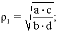
где ρ1 - абсолютное значение коэффициента отражения первого исследуемого зеркала;where ρ 1 is the absolute value of the reflection coefficient of the first investigated mirror;
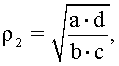
ρ2 - абсолютное значение коэффициента отражения второго исследуемого зеркала;ρ 2 - the absolute value of the reflection coefficient of the second studied mirror;
а - сигнал фотоприемника, соответствующий потоку излучения с двумя исследуемыми зеркалами;a - photodetector signal corresponding to the radiation flux with two studied mirrors;
b - сигнал фотоприемника, соответствующий опорному потоку излучения в отсутствии исследуемых зеркал;b is the photodetector signal corresponding to the reference radiation flux in the absence of the studied mirrors;
с - сигнал фотоприемника, соответствующий потоку излучения с первым исследуемым зеркалом;c is the photodetector signal corresponding to the radiation flux with the first studied mirror;
d - сигнал фотоприемника, соответствующий потоку излучения со вторым исследуемым зеркалом.d is the photodetector signal corresponding to the radiation flux with the second studied mirror.
На чертеже показана оптическая схема устройства, реализующего способ измерений абсолютного значения коэффициента отражения зеркал.The drawing shows an optical diagram of a device that implements a method of measuring the absolute value of the reflection coefficient of mirrors.
Устройство содержит исследуемые зеркала 1 и 2, источник излучения в виде выходной щели 3 монохроматора, коллимационный объектив 4, формирующий параллельный поток излучения, апертурную диафрагму 5, расположенные по ходу потока излучения перекидное плоское зеркало 6, плоское зеркало 7, объектив 8, плоское зеркало 9, снабженное механизмом линейного перемещения вдоль оси, перпендикулярной оси параллельного потока излучения, и механизмом поворота на 90°, ориентирующим отражающую поверхность зеркала в направлении параллельного потока излучения и в направлении потока излучения, отраженного от исследуемых зеркал 1 и 2, объектив 10 фотоприемной системы и фотоприемник 11.The device contains the studied mirrors 1 and 2, a radiation source in the form of an output slit 3 of a monochromator, a collimation lens 4 forming a parallel radiation flux, an aperture diaphragm 5, a flip flat mirror 6 located along the radiation flux, a flat mirror 7, a lens 8, a flat mirror 9 equipped with a linear displacement mechanism along an axis perpendicular to the axis of the parallel radiation flux, and a 90 ° rotation mechanism orienting the reflective surface of the mirror in the direction of the parallel radiation flux and in the direction of the radiation flux reflected from the studied mirrors 1 and 2, the lens 10 of the photodetector system and the photodetector 11.
Способ измерения осуществляют следующим образом. Устанавливают плоское зеркало 9 в положение III, а плоское зеркало 6 в положение II, при котором параллельный поток излучения освещает исследуемое зеркало 1, оптически сопряженное с исследуемым зеркалом 2. Совмещают фокусы исследуемых зеркал. Отраженный от исследуемого зеркала 2 параллельный поток излучения направляют плоским зеркалом 9 на объектив 10 фотоприемной системы. Измеряют сигнал а фотоприемника 11, соответствующий потоку излучения с двумя исследуемыми зеркалами 1 и 2. Величина этого сигнала а=L·τ4·ρ6·ρ1·ρ2·ρ9·τ10,The measurement method is as follows. Set the flat mirror 9 to position III, and the flat mirror 6 to position II, in which a parallel radiation flux illuminates the studied mirror 1, which is optically coupled to the studied mirror 2. Combine the foci of the studied mirrors. Reflected from the studied mirror 2, the parallel radiation flux is directed by a flat mirror 9 to the lens 10 of the photodetector system. The signal a of the photodetector 11 is measured, which corresponds to the radiation flux with two studied mirrors 1 and 2. The value of this signal is a = L · τ 4 · ρ 6 · ρ 1 · ρ 2 · ρ 9 · τ 10 ,
где L - яркость источника излучения;where L is the brightness of the radiation source;
τ4 - коэффициент пропускания коллимационного объектива 4;τ 4 - transmittance of the collimation lens 4;
ρ6 - коэффициент отражения плоского зеркала 6;ρ 6 is the reflection coefficient of a flat mirror 6;
ρ1 и ρ2 - коэффициенты отражения исследуемых зеркал 1 и 2;ρ 1 and ρ 2 are the reflection coefficients of the studied mirrors 1 and 2;
ρ9 - коэффициент отражения плоского зеркала 9;ρ 9 is the reflection coefficient of a flat mirror 9;
τ10 - коэффициент пропускания объектива 10 фотоприемной системы.τ 10 - transmittance of the lens 10 of the photodetector system.
Направляют параллельный поток излучения плоским зеркалом 9, которое устанавливают в положении I, на объектив 10 фотоприемной системы и измеряют сигнал b фотоприемника 11, соответствующий опорному потоку излучения в отсутствии исследуемых зеркал 1 и 2. Сигнал фотоприемника 11 в этом случае b=L·τ4·ρ6·ρ9·τ10. The parallel radiation flux is directed by a flat mirror 9, which is set in position I, to the objective 10 of the photodetector system and the signal b of the photodetector 11 is measured, which corresponds to the reference radiation flux in the absence of the mirrors 1 and 2. In this case, the signal of the photodetector b = L · τ 4 · Ρ 6 · ρ 9 · τ 10.
Устанавливают плоское зеркало 6 в положение I и преобразуют объективом 8 параллельный поток излучения в сходящийся. Совмещают фокусы объектива 8 и исследуемого зеркала 1. Параллельный поток излучения, отраженный от исследуемого зеркала 1, направляют плоским зеркалом 9, установленным в положение II, на объектив 10 фотоприемной системы и измеряют сигнал с фотоприемника 11, соответствующий потоку излучения с исследуемым зеркалом 1, c=L·τ4·ρ7·τ8·ρ1·ρ9·τ10, Set the flat mirror 6 to position I and convert the parallel radiation flux to convergent by the lens 8. Combine the foci of the lens 8 and the studied mirror 1. The parallel radiation flux reflected from the studied mirror 1 is directed by a flat mirror 9 installed in position II to the lens 10 of the photodetector system and the signal from the photodetector 11 is measured, which corresponds to the radiation flux with the studied mirror 1, c = L · τ 4 · ρ 7 · τ 8 · ρ 1 · ρ 9 · τ 10 ,
где τ8 - коэффициент пропускания объектива 8;where τ 8 is the transmittance of the lens 8;
ρ7 - коэффициент отражения плоского зеркала 7.ρ 7 is the reflection coefficient of a flat mirror 7.
Устанавливают вместо исследуемого зеркала 1 зеркало 2 и аналогично измеряют сигнал d фотоприемника 11, соответствующий потоку излучения с исследуемым зеркалом 2, d=L·τ4·ρ7·τ8·ρ2·ρ9·τ10.Instead of the studied mirror 1, they install mirror 2 and similarly measure the signal d of the photodetector 11 corresponding to the radiation flux with the studied mirror 2, d = L · τ 4 · ρ 7 · τ 8 · ρ 2 · ρ 9 · τ 10 .
По результатам измерений получают два независимых уравнения:According to the measurement results, two independent equations are obtained:
![]()
![]()
![]()
![]()
где ρ1 - абсолютное значение коэффициента отражения первого исследуемого зеркала;where ρ 1 is the absolute value of the reflection coefficient of the first investigated mirror;
ρ2 - абсолютное значение коэффициента отражения второго исследуемого зеркала;ρ 2 - the absolute value of the reflection coefficient of the second studied mirror;
а - сигнал фотоприемника, соответствующий потоку излучения с двумя исследуемыми зеркалами;a - photodetector signal corresponding to the radiation flux with two studied mirrors;
b - сигнал фотоприемника, соответствующий опорному потоку излучения в отсутствии исследуемых зеркал;b is the photodetector signal corresponding to the reference radiation flux in the absence of the studied mirrors;
с - сигнал фотоприемника, соответствующий потоку излучения с первым исследуемым зеркалом;c is the photodetector signal corresponding to the radiation flux with the first studied mirror;
d - сигнал фотоприемника, соответствующий потоку излучения со вторым исследуемым зеркалом.d is the photodetector signal corresponding to the radiation flux with the second studied mirror.
В соответствии со способом измерены абсолютные значения спектрального коэффициента отражения внеосевых параболических зеркал (уравнение параболы y2=1080x, световой диаметр dсв=62 мм) с зеркальным покрытием МД.В.029 по ОСТ 3-1901-95. Измерения выполнены с монохроматором МДР - 12 в области спектра от 3 до 14 мкм. Источником излучения являлся карбидокремниевый излучатель (глобар) при температуре Т=1400 К. В качестве приемника излучения использовался оптико-акустический приемник излучения ОАП-7-1; регистрирующим прибором служил мультиметр Agilent 3458A. Абсолютное значение спектрального коэффициента отражения в области спектра (3…5) мкм изменялось в пределах от 0,962 до 0,966, а в области спектра (8…14) мкм - от 0,965 до 0,980. Погрешность регистрации сигналов не превышала 0,3%; суммарная расчетная погрешность измерений составляла не более 0,8%.In accordance with the method of measured absolute values of the spectral reflectance of the off-axis parabolic mirror (parabolic equation y 2 = 1080x, light communication diameter d = 62 mm) with a mirror coating MD.V.029 OST 3-1901-95. The measurements were performed with an MDR-12 monochromator in the spectral region from 3 to 14 μm. The radiation source was a silicon carbide emitter (globar) at a temperature of T = 1400 K. An optical-acoustic radiation detector OAP-7-1 was used as a radiation detector; the recording instrument was an Agilent 3458A multimeter. The absolute value of the spectral reflection coefficient in the spectral region (3 ... 5) μm varied from 0.962 to 0.966, and in the spectrum region (8 ... 14) μm - from 0.965 to 0.980. The error in the registration of signals did not exceed 0.3%; the total calculated measurement error was not more than 0.8%.
При измерениях потоков излучения, взаимодействующих с двумя исследуемыми зеркалами, влияние внешних факторов полностью исключалось поочередной регистрацией сигналов а и b.When measuring radiation fluxes interacting with two studied mirrors, the influence of external factors was completely excluded by alternating recording of signals a and b.
Claims (1)
где ρ1 - абсолютное значение коэффициента отражения первого исследуемого зеркала; ρ2 - абсолютное значение коэффициента отражения второго исследуемого зеркала; а - сигнал фотоприемника, соответствующий потоку излучения с двумя исследуемыми зеркалами;
b - сигнал фотоприемника, соответствующий опорному потоку излучения в отсутствии исследуемых зеркал; с - сигнал фотоприемника, соответствующий потоку излучения с первым исследуемым зеркалом;
d - сигнал фотоприемника, соответствующий потоку излучения со вторым исследуемым зеркалом. The method of measuring the absolute value of the reflection coefficient of the mirrors, during which the radiation flux is formed using the optical system, measure the radiation flux at the output of the optical system with a photodetector in the presence of the studied mirror, measure the reference radiation flux in the absence of the studied mirror and determine the reflection coefficient by the formula, characterized in that that two mirrors are used as the studied ones, they illuminate the first studied mirror along the stream with a parallel radiation flux, combine the pieces of the studied mirrors, the parallel radiation flux reflected from the second studied mirror is directed by a flat mirror to the objective of the photodetector system and the corresponding radiation flux is measured, the parallel radiation flux is directed by the flat mirror to the objective of the photodetector system and the reference radiation flux is measured in the absence of the studied mirrors, the parallel radiation flux is converted by the lens in converging, combine the focus of the lens with the focus of the first investigated mirror, a parallel radiation flux reflected m first test mirror, flat mirror, directed to the lens system and the photodetector is measured corresponding to the radiation flux is set instead of the first and second test mirror similarly measured corresponding to the radiation flux, and the absolute value of mirror reflectivity coefficient determined by the formulas:
where ρ 1 is the absolute value of the reflection coefficient of the first investigated mirror; ρ 2 - the absolute value of the reflection coefficient of the second studied mirror; a - photodetector signal corresponding to the radiation flux with two studied mirrors;
b is the photodetector signal corresponding to the reference radiation flux in the absence of the studied mirrors; c is the photodetector signal corresponding to the radiation flux with the first studied mirror;
d is the photodetector signal corresponding to the radiation flux with the second studied mirror.
Priority Applications (1)
| Application Number | Priority Date | Filing Date | Title |
|---|---|---|---|
| RU2010102383/28A RU2424503C1 (en) | 2010-01-25 | 2010-01-25 | Method of measuring absolute value of mirror reflectivity |
Applications Claiming Priority (1)
| Application Number | Priority Date | Filing Date | Title |
|---|---|---|---|
| RU2010102383/28A RU2424503C1 (en) | 2010-01-25 | 2010-01-25 | Method of measuring absolute value of mirror reflectivity |
Publications (1)
| Publication Number | Publication Date |
|---|---|
| RU2424503C1 true RU2424503C1 (en) | 2011-07-20 |
Family
ID=44752628
Family Applications (1)
| Application Number | Title | Priority Date | Filing Date |
|---|---|---|---|
| RU2010102383/28A RU2424503C1 (en) | 2010-01-25 | 2010-01-25 | Method of measuring absolute value of mirror reflectivity |
Country Status (1)
| Country | Link |
|---|---|
| RU (1) | RU2424503C1 (en) |
Cited By (1)
| Publication number | Priority date | Publication date | Assignee | Title |
|---|---|---|---|---|
| RU2822502C1 (en) * | 2023-10-11 | 2024-07-08 | Федеральное государственное бюджетное образовательное учреждение высшего образования "Рязанский государственный радиотехнический университет имени В.Ф. Уткина" | Reflectometer |
Citations (4)
| Publication number | Priority date | Publication date | Assignee | Title |
|---|---|---|---|---|
| SU1286963A1 (en) * | 1984-09-01 | 1987-01-30 | Предприятие П/Я Х-5827 | Method and apparatus for measuring absolute reflection factor of mirror |
| SU1562793A1 (en) * | 1988-05-12 | 1990-05-07 | Предприятие П/Я А-1705 | Device for measuring absolute coefficients of mirror reflection |
| SU1601564A1 (en) * | 1988-07-07 | 1990-10-23 | Предприятие П/Я Г-4671 | Device for measuring reflection factor of concave spherical surfaces |
| US5313270A (en) * | 1992-05-07 | 1994-05-17 | The Board Of Trustees Of The Leland Stanford Junior University | Method and apparatus for measurement of reflectivity for high quality mirrors |
-
2010
- 2010-01-25 RU RU2010102383/28A patent/RU2424503C1/en active
Patent Citations (4)
| Publication number | Priority date | Publication date | Assignee | Title |
|---|---|---|---|---|
| SU1286963A1 (en) * | 1984-09-01 | 1987-01-30 | Предприятие П/Я Х-5827 | Method and apparatus for measuring absolute reflection factor of mirror |
| SU1562793A1 (en) * | 1988-05-12 | 1990-05-07 | Предприятие П/Я А-1705 | Device for measuring absolute coefficients of mirror reflection |
| SU1601564A1 (en) * | 1988-07-07 | 1990-10-23 | Предприятие П/Я Г-4671 | Device for measuring reflection factor of concave spherical surfaces |
| US5313270A (en) * | 1992-05-07 | 1994-05-17 | The Board Of Trustees Of The Leland Stanford Junior University | Method and apparatus for measurement of reflectivity for high quality mirrors |
Cited By (1)
| Publication number | Priority date | Publication date | Assignee | Title |
|---|---|---|---|---|
| RU2822502C1 (en) * | 2023-10-11 | 2024-07-08 | Федеральное государственное бюджетное образовательное учреждение высшего образования "Рязанский государственный радиотехнический университет имени В.Ф. Уткина" | Reflectometer |
Similar Documents
| Publication | Publication Date | Title |
|---|---|---|
| KR102696735B1 (en) | Instantaneous ellipsometer or scatterometer and related measuring methods | |
| TWI280349B (en) | Spectrum measurement apparatus | |
| CN107462405B (en) | Method and device for measuring refractive index of broadband differential confocal infrared lens element | |
| TW200409904A (en) | Apparatus for measuring film thickness formed on object, apparatus and method of measuring spectral reflectance of object, and apparatus and method of inspecting foreign material on object | |
| JP2019095799A5 (en) | ||
| US7298468B2 (en) | Method and measuring device for contactless measurement of angles or angle changes on objects | |
| WO2011150680A1 (en) | Broadband polarization spectrometer with normal incidence and optical measuring system | |
| RU2690723C1 (en) | Method and device for automatic adjustment of mirror telescopes | |
| CN103162831A (en) | Broadband polarization spectrometer and optical measurement system | |
| CN103245488B (en) | A kind of broadband large scale plane raster diffraction efficiency measurer | |
| CN103344416A (en) | Volume holographic transmission grating diffraction efficiency tester | |
| RU181779U1 (en) | Device for measuring the integral scattering coefficient over the surface of mirrors | |
| KR101620594B1 (en) | spectroscopy apparatus | |
| CN107782697B (en) | Method and device for measuring refractive index of broadband confocal infrared lens element | |
| CN105589191B (en) | The focus cameras and its focus adjustment method confocal for adjusting astronomical telescope system | |
| RU2424503C1 (en) | Method of measuring absolute value of mirror reflectivity | |
| JP2009085600A (en) | Optical characteristic measuring instrument and method | |
| RU2531555C2 (en) | Autocollimation method of changing focal distance | |
| RU166499U1 (en) | DEVICE FOR MEASURING THE DISTRIBUTION OF THE INTEGRAL LIGHT SCATTERING FACTOR BY THE MIRROR SURFACE | |
| CN117606756A (en) | A lens assembly adjustment and detection device and detection method | |
| RU2688961C1 (en) | Device for measuring bidirectional infrared radiation brightness coefficient of materials | |
| RU2427814C1 (en) | Method of measuring lens transmission coefficient | |
| TW201105929A (en) | Interference measuring device and measuring method thereof | |
| RU2422790C1 (en) | Method of measuring lens transmittance | |
| TWI898876B (en) | Optical measuring system and method for measuring critical dimension |