RU2423725C2 - Scintillators for detecting radiation, as well as corresponding methods and devices - Google Patents
Scintillators for detecting radiation, as well as corresponding methods and devices Download PDFInfo
- Publication number
- RU2423725C2 RU2423725C2 RU2007121268/28A RU2007121268A RU2423725C2 RU 2423725 C2 RU2423725 C2 RU 2423725C2 RU 2007121268/28 A RU2007121268/28 A RU 2007121268/28A RU 2007121268 A RU2007121268 A RU 2007121268A RU 2423725 C2 RU2423725 C2 RU 2423725C2
- Authority
- RU
- Russia
- Prior art keywords
- matrix material
- group
- scintillator
- radiation
- alkaline earth
- Prior art date
Links
Images

Classifications
-
- C—CHEMISTRY; METALLURGY
- C09—DYES; PAINTS; POLISHES; NATURAL RESINS; ADHESIVES; COMPOSITIONS NOT OTHERWISE PROVIDED FOR; APPLICATIONS OF MATERIALS NOT OTHERWISE PROVIDED FOR
- C09K—MATERIALS FOR MISCELLANEOUS APPLICATIONS, NOT PROVIDED FOR ELSEWHERE
- C09K11/00—Luminescent, e.g. electroluminescent, chemiluminescent materials
- C09K11/08—Luminescent, e.g. electroluminescent, chemiluminescent materials containing inorganic luminescent materials
- C09K11/77—Luminescent, e.g. electroluminescent, chemiluminescent materials containing inorganic luminescent materials containing rare earth metals
- C09K11/7766—Luminescent, e.g. electroluminescent, chemiluminescent materials containing inorganic luminescent materials containing rare earth metals containing two or more rare earth metals
- C09K11/7772—Halogenides
- C09K11/7773—Halogenides with alkali or alkaline earth metal
-
- C—CHEMISTRY; METALLURGY
- C09—DYES; PAINTS; POLISHES; NATURAL RESINS; ADHESIVES; COMPOSITIONS NOT OTHERWISE PROVIDED FOR; APPLICATIONS OF MATERIALS NOT OTHERWISE PROVIDED FOR
- C09K—MATERIALS FOR MISCELLANEOUS APPLICATIONS, NOT PROVIDED FOR ELSEWHERE
- C09K11/00—Luminescent, e.g. electroluminescent, chemiluminescent materials
- C09K11/08—Luminescent, e.g. electroluminescent, chemiluminescent materials containing inorganic luminescent materials
- C09K11/55—Luminescent, e.g. electroluminescent, chemiluminescent materials containing inorganic luminescent materials containing beryllium, magnesium, alkali metals or alkaline earth metals
-
- C—CHEMISTRY; METALLURGY
- C09—DYES; PAINTS; POLISHES; NATURAL RESINS; ADHESIVES; COMPOSITIONS NOT OTHERWISE PROVIDED FOR; APPLICATIONS OF MATERIALS NOT OTHERWISE PROVIDED FOR
- C09K—MATERIALS FOR MISCELLANEOUS APPLICATIONS, NOT PROVIDED FOR ELSEWHERE
- C09K11/00—Luminescent, e.g. electroluminescent, chemiluminescent materials
- C09K11/08—Luminescent, e.g. electroluminescent, chemiluminescent materials containing inorganic luminescent materials
- C09K11/66—Luminescent, e.g. electroluminescent, chemiluminescent materials containing inorganic luminescent materials containing germanium, tin or lead
-
- G—PHYSICS
- G01—MEASURING; TESTING
- G01T—MEASUREMENT OF NUCLEAR OR X-RADIATION
- G01T1/00—Measuring X-radiation, gamma radiation, corpuscular radiation, or cosmic radiation
- G01T1/16—Measuring radiation intensity
- G01T1/20—Measuring radiation intensity with scintillation detectors
-
- G—PHYSICS
- G01—MEASURING; TESTING
- G01T—MEASUREMENT OF NUCLEAR OR X-RADIATION
- G01T1/00—Measuring X-radiation, gamma radiation, corpuscular radiation, or cosmic radiation
- G01T1/16—Measuring radiation intensity
- G01T1/20—Measuring radiation intensity with scintillation detectors
- G01T1/202—Measuring radiation intensity with scintillation detectors the detector being a crystal
-
- G—PHYSICS
- G21—NUCLEAR PHYSICS; NUCLEAR ENGINEERING
- G21K—TECHNIQUES FOR HANDLING PARTICLES OR IONISING RADIATION NOT OTHERWISE PROVIDED FOR; IRRADIATION DEVICES; GAMMA RAY OR X-RAY MICROSCOPES
- G21K4/00—Conversion screens for the conversion of the spatial distribution of X-rays or particle radiation into visible images, e.g. fluoroscopic screens
Abstract
Description
Уровень техникиState of the art
Настоящее изобретение относится к люминесцирующим веществам, к примеру веществам, используемым для того, чтобы обнаруживать ионизирующее излучение. В некоторых конкретных вариантах осуществления изобретение относится к сцинтилляционным составам (и соответствующим устройствам), которые особенно пригодны для обнаружения гамма-лучей и рентгеновских лучей.The present invention relates to luminescent substances, for example, substances used to detect ionizing radiation. In certain specific embodiments, the invention relates to scintillation compositions (and related devices) that are particularly suitable for detecting gamma rays and x-rays.
Известно множество методик обнаружения излучения высокой энергии. Многие из них базируются на использовании сцинтилляционных веществ. Твердотельные сцинтилляторы широко используются в качестве компонента детекторов излучений для гамма-лучей, рентгеновских лучей, космических лучей и частиц, отличающихся уровнем энергии выше примерно 1 килоэлектронвольт. Кристалл сцинтиллятора соединяется со средством детектирования света, т.е. фотодетектором. Когда фотоны из источника соударяются с кристаллом, кристалл испускает свет. Фотодетектор формирует электрический сигнал пропорционально числу принятых световых импульсов, а также их интенсивности.Many techniques for detecting high energy radiation are known. Many of them are based on the use of scintillation substances. Solid state scintillators are widely used as a component of radiation detectors for gamma rays, x-rays, cosmic rays and particles with energy levels above about 1 kiloelectron-volt. The scintillator crystal is connected to a light detecting means, i.e. photo detector. When photons from a source collide with a crystal, the crystal emits light. The photodetector generates an electrical signal in proportion to the number of received light pulses, as well as their intensity.
Обнаружено, что сцинтилляторы полезны для вариантов применения в химии, геологии и медицине. Конкретные примеры вариантов применения включают в себя устройства позитронной эмиссионной томографии (PET); каротаж скважин в нефтегазовой промышленности и различные приложения цифровой обработки изображений. Сцинтилляторы также изучаются на предмет использования в детекторах защитных устройств, к примеру в детекторах источников излучения, которые могут показывать наличие радиоактивных веществ в грузовых контейнерах.Scintillators have been found to be useful for applications in chemistry, geology, and medicine. Specific examples of applications include positron emission tomography (PET) devices; well logging in the oil and gas industry and various digital imaging applications. Scintillators are also being studied for the use of protective devices in detectors, for example, in radiation source detectors, which can indicate the presence of radioactive substances in cargo containers.
Конкретный состав сцинтиллятора является очень важным для характеристик устройства. Сцинтиллятор должен реагировать на возбуждение рентгеновскими лучами и гамма-лучами. Более того, сцинтиллятор должен обладать рядом характеристик, которые улучшают обнаружение излучения. Например, большинство веществ сцинтиллятора должны обладать одной или более из следующих характеристик: высокий световой выход, малое время послесвечения, высокая "энергия останова" и приемлемое энергетическое разрешение. (Другие свойства также могут быть очень существенны, в зависимости от того, как используется сцинтиллятор, как упоминается ниже).The specific composition of the scintillator is very important for the characteristics of the device. The scintillator must respond to excitation by x-rays and gamma rays. Moreover, the scintillator should have a number of characteristics that improve radiation detection. For example, most scintillator substances should have one or more of the following characteristics: high light output, short afterglow, high “stopping energy,” and acceptable energy resolution. (Other properties can also be very significant, depending on how the scintillator is used, as mentioned below).
Различные вещества сцинтиллятора, которые обладают большей частью или всеми этими свойствами, использовались в течение многих лет. Примеры включают в себя активированный таллием иодид натрия (NaI(Tl)); германат висмута (BGO); ортосиликат гадолиния с примесью церия (GSO); ортосиликат лютеция с примесью церия (LSO); и активированные церием соединения галогенидов лантанидов. Каждое из этих веществ имеет свойства, которые оптимально подходят для конкретных вариантов применения. Тем не менее, многие из них имеют определенные недостатки. Общераспространенные проблемы - это низкий световой выход, физическая непрочность, неспособность формировать крупноразмерные высококачественные монокристаллы. Также имеются другие недостатки. Например, активированные таллием вещества являются очень гигроскопическими и также могут формировать значительное и устойчивое послесвечение, что может мешать работе сцинтиллятора. Более того, вещества BGO зачастую имеют замедленное время послесвечения. С другой стороны, вещества LSO являются дорогими и также могут содержать радиоактивные изотопы лютеция, что также может мешать работе сцинтиллятора.Various scintillator substances that possess most or all of these properties have been used for many years. Examples include thallium activated sodium iodide (NaI (Tl)); bismuth germanate (BGO); cadmium-doped gadolinium orthosilicate (GSO); cerium-mixed lutetium orthosilicate (LSO); and cerium-activated lanthanide halide compounds. Each of these substances has properties that are optimally suited to specific applications. However, many of them have certain disadvantages. Common problems are low light output, physical fragility, inability to form large-sized high-quality single crystals. There are also other disadvantages. For example, thallium-activated substances are very hygroscopic and can also form a significant and stable afterglow, which can interfere with the operation of the scintillator. Moreover, BGO substances often have a delayed afterglow. On the other hand, LSOs are expensive and may also contain radioactive isotopes of lutetium, which can also interfere with the operation of the scintillator.
В общем, заинтересованные в получении оптимального сцинтилляционного состава для детектора излучения могли проанализировать различные атрибуты, указанные выше, и тем самым выбрать оптимальный состав для конкретного устройства. (В качестве только одного примера, сцинтилляционные составы для вариантов применения каротажа скважин должны иметь возможность функционировать при высоких температурах, тогда как сцинтилляторы для РЕТ-устройств зачастую должны иметь высокую энергию останова). Тем не менее, требуемый уровень общей характеристики для большинства сцинтилляторов продолжает возрастать с увеличением сложности и многообразия всех детекторов излучения.In general, those interested in obtaining the optimal scintillation composition for a radiation detector could analyze the various attributes indicated above, and thereby choose the optimal composition for a particular device. (As just one example, scintillation formulations for well logging applications should be able to operate at high temperatures, while scintillators for PET devices often must have high shutdown energy). However, the required level of overall performance for most scintillators continues to increase with increasing complexity and diversity of all radiation detectors.
Учитывая все вышеизложенные соображения, преимущества раскрытия новых сцинтилляционных веществ являются очевидными. Вещества должны иметь превосходный световой выход. Они также должны обладать одной или более требуемыми характеристиками, такими как относительно быстрое время послесвечения и хорошие характеристики энергетического разрешения, особенно в случае гамма-лучей. Более того, они должны допускать эффективное изготовление при разумной стоимости и приемлемом размере кристалла.Given all the above considerations, the advantages of the discovery of new scintillation substances are obvious. Substances must have excellent light output. They should also have one or more required characteristics, such as a relatively fast afterglow time and good energy resolution characteristics, especially in the case of gamma rays. Moreover, they must allow efficient manufacturing at a reasonable cost and an acceptable crystal size.
Раскрытие изобретенияDisclosure of invention
Первый вариант осуществления этого изобретения направлен на сцинтилляционный состав, содержащий следующие элементы и все их продукты реакции:The first embodiment of this invention is directed to a scintillation composition containing the following elements and all their reaction products:
(a) материал матрицы, содержащий:(a) matrix material containing:
(i) по меньшей мере, один элемент, выбранный из группы, состоящей из щелочноземельных металлов и свинца;(i) at least one element selected from the group consisting of alkaline earth metals and lead;
(ii) по меньшей мере, один галогенид лантанида; и(ii) at least one lanthanide halide; and
(b) активатор для материала матрицы, содержащий церий, празеодимий или смесь церия и празеодимия.(b) an activator for the matrix material containing cerium, praseodymium or a mixture of cerium and praseodymium.
Другой вариант осуществления относится к детектору излучения для обнаружения излучения высокой энергии. Детектор содержит средство обнаружения света (к примеру, фотодетектор), соединенное с кристаллом сцинтиллятора, как описано в данном документе.Another embodiment relates to a radiation detector for detecting high energy radiation. The detector comprises light detection means (e.g., a photodetector) coupled to a scintillator crystal, as described herein.
Способ обнаружения излучения высокой энергии с помощью сцинтилляционного детектора представляет другой вариант осуществления. Способ содержит этапы:A method for detecting high energy radiation using a scintillation detector is another embodiment. The method comprises the steps of:
(A) приема излучения посредством кристалла сцинтиллятора, описываемого в данной заявке, с тем чтобы формировать фотоны, которые являются характеристикой излучения; и(A) receiving radiation through a scintillator crystal described herein in order to form photons that are characteristic of radiation; and
(B) обнаружения фотонов с помощью детектора фотонов, соединенного с кристаллом сцинтиллятора.(B) detecting photons using a photon detector coupled to a scintillator crystal.
Другие признаки и преимущества изобретения должны стать очевидными из прочтения оставшейся части данного подробного описания.Other features and advantages of the invention should become apparent from reading the remainder of this detailed description.
Краткое описание чертежейBrief Description of the Drawings
Фиг.1 - это график спектра излучения (при возбуждении рентгеновскими лучами) для сцинтилляционного состава согласно варианту осуществления настоящего изобретения.1 is a graph of a radiation spectrum (when excited by x-rays) for a scintillation composition according to an embodiment of the present invention.
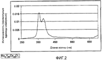
Фиг.2 - это график спектра излучения для состава, аналогичного составу на фиг.1, с другими соотношениями компонентов.Figure 2 is a graph of the radiation spectrum for a composition similar to the composition in figure 1, with other ratios of components.
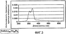
Фиг.3 - это график спектра излучения (при возбуждении рентгеновскими лучами) для другого сцинтилляционного состава согласно варианту осуществления настоящего изобретения.Figure 3 is a graph of a radiation spectrum (when excited by x-rays) for another scintillation composition according to an embodiment of the present invention.
Фиг.4 - это график спектра излучения для состава, аналогичного составу на фиг.3, с другими соотношениями компонентов.Figure 4 is a graph of the radiation spectrum for a composition similar to the composition in figure 3, with other ratios of components.
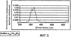
Фиг.5 - это график спектра излучения другого состава, аналогичного составу на фиг.3, с другими соотношениями компонентов.FIG. 5 is a graph of a radiation spectrum of another composition similar to that of FIG. 3, with different ratios of components.
Осуществление изобретенияThe implementation of the invention
Один компонент материала матрицы, компонент a(i), содержит, по меньшей мере, один элемент, выбранный из группы, состоящей из щелочноземельных металлов и свинца. Щелочноземельным металлом может быть магний, кальций, стронций или барий. (Сам барий является наиболее предпочтительным щелочноземельным металлом в некоторых вариантах осуществления). Более того, множество различных комбинаций из двух или более щелочноземельных металлов (со свинцом или без свинца) также может быть использовано. В некоторых вариантах осуществления барий, кальций или комбинации бария и кальция являются предпочтительными. В других вариантах осуществления три щелочноземельных металла может быть использовано, либо комбинация из двух щелочноземельных металлов и свинца, к примеру бария, стронция и свинца.One component of the matrix material, component a (i), contains at least one element selected from the group consisting of alkaline earth metals and lead. The alkaline earth metal may be magnesium, calcium, strontium or barium. (Barium itself is the most preferred alkaline earth metal in some embodiments). Moreover, many different combinations of two or more alkaline earth metals (with or without lead) can also be used. In some embodiments, barium, calcium, or combinations of barium and calcium are preferred. In other embodiments, three alkaline earth metals may be used, or a combination of two alkaline earth metals and lead, for example barium, strontium and lead.
Компонент a(ii) материала матрицы содержит, по меньшей мере, один галогенид лантанида. Галогеном является бром, хлор или йод. Каждый из отдельных галогенидов может быть полезен для конкретных вариантов применения. Бром или хлор зачастую являются предпочтительными для некоторых вариантов осуществления. Тем не менее, в других вариантах осуществления предпочтительным может быть йод. (Например, йод в некоторых случаях имеет очень высокие характеристики светового вывода).Component a (ii) of the matrix material contains at least one lanthanide halide. Halogen is bromine, chlorine or iodine. Each of the individual halides may be useful for specific applications. Bromine or chlorine are often preferred for some embodiments. However, in other embodiments, iodine may be preferred. (For example, iodine in some cases has very high light output characteristics).
Лантанидом компонента a(ii) может быть любой из редкоземельных металлов, т.е. лантан, церий, празеодимий, неодим, самарий, европий, гадолиний, тербий, диспрозий, гольмий, эрбий, тулий, иттербий и лютеций. Смеси из двух или более лантанидов также возможны. (Специалисты в данной области техники должны понимать, что иттрий и скандий тесно связаны с редкоземельной группой. Таким образом, в контексте данной заявки эти два элемента также рассматриваются как часть семейства лантанидов). Предпочтительные лантаниды выбираются из группы, состоящей из лантана, иттрия, гадолиния, лютеция, скандия, празеодимия и их смесей. В особенно предпочтительных вариантах осуществления лантанидом является сам лантан.The lanthanide of component a (ii) may be any of the rare earth metals, i.e. lanthanum, cerium, praseodymium, neodymium, samarium, europium, gadolinium, terbium, dysprosium, holmium, erbium, thulium, ytterbium and lutetium. Mixtures of two or more lanthanides are also possible. (Those skilled in the art should understand that yttrium and scandium are closely related to the rare earth group. Thus, in the context of this application, these two elements are also considered as part of the lanthanide family). Preferred lanthanides are selected from the group consisting of lanthanum, yttrium, gadolinium, lutetium, scandium, praseodymium and mixtures thereof. In particularly preferred embodiments, the lanthanide is lanthanum itself.
Некоторые конкретные неограничивающие примеры галогенидов лантанидов следующие: хлорид лютеция, бромид лютеция, йодид лютеция, хлорид иттрия, бромид иттрия, йодид иттрия, хлорид гадолиния, бромид гадолиния, хлорид празеодимия, бромид празеодимия и их смеси. В некоторых вариантах осуществления используются галогениды лантана, т.е. йодид лантана (LaI3), бромид лантана (LaBr3), хлорид лантана (LaCl3) и их смеси, к примеру твердый раствор из, по меньшей мере, двух галогенидов лантана.Some specific non-limiting examples of lanthanide halides are: lutetium chloride, lutetium bromide, lutetium iodide, yttrium chloride, yttrium bromide, yttrium iodide, gadolinium chloride, gadolinium bromide, praseodymium chloride, praseodymium bromide and mixtures thereof. In some embodiments, lanthanum halides, i.e. lanthanum iodide (LaI 3 ), lanthanum bromide (LaBr 3 ), lanthanum chloride (LaCl 3 ), and mixtures thereof, for example, a solid solution of at least two lanthanum halides.
Некоторые конкретные семейства сцинтилляторов для конкретных вариантов осуществления также могут быть описаны. Например, материал матрицы сцинтиллятора может содержать соединение по формулеSome specific scintillator families for specific embodiments may also be described. For example, the scintillator matrix material may contain a compound of the formula
![]()
![]()
илиor
![]()
![]()
где β - это, по меньшей мере, один элемент, выбранный из группы, состоящей из щелочноземельных металлов и свинца; Ln - это, по меньшей мере, один лантанид; а X выбирается из группы, состоящей из брома, хрома, йода и их комбинаций.where β is at least one element selected from the group consisting of alkaline earth metals and lead; Ln is at least one lanthanide; and X is selected from the group consisting of bromine, chromium, iodine, and combinations thereof.
Неограничивающие примеры соединений согласно формуле (I) следующие:Non-limiting examples of compounds according to formula (I) are as follows:
BaGdCl5, BaLaCl5, BaGdBr5, BaLuCl5, PbGdCl5 и CaGdCl5.BaGdCl 5 , BaLaCl 5 , BaGdBr 5 , BaLuCl 5 , PbGdCl 5 and CaGdCl 5 .
Неограничивающие примеры соединений согласно формуле (II) следующие:Non-limiting examples of compounds according to formula (II) are as follows:
Ba2YCl7, Ba2GdCl7, Ba2LaCl7, Ba2LuCl7, Ba2YBr7, Ba2YI7, Ba2LaBr7, Ba2LaI7, Sr2YCl7, BaSrYCl7, BaSrLaCl7, BaSrLuCl7, BaSrYBr7, BaSrLaBr7, BaSrLuBr7, Ca2YCl7, Ca2YBr7, Ca2LaCl7, Ca2LuCl7, Pb2YCl7, Pb2YBr7, Pb2LaCl7 и Pb2LuCl7.Ba 2 YCl 7 , Ba 2 GdCl 7 , Ba 2 LaCl 7 , Ba 2 LuCl 7 , Ba 2 YBr 7 , Ba 2 YI 7 , Ba 2 LaBr 7 , Ba 2 LaI 7 , Sr 2 YCl 7 , BaSrYCl 7 , BaSrLaCl 7 , BaSrLuCl 7 , BaSrYBr 7 , BaSrLaBr 7 , BaSrLuBr 7 , Ca 2 YCl 7 , Ca 2 YBr 7 , Ca 2 LaCl 7 , Ca 2 LuCl 7 , Pb 2 YCl 7 , Pb 2 YBr 7 , Pb 2 LaCl 7 and Pb 2 LuCl 7 .
Некоторые из материалов матрицы, которые являются предпочтительными для конкретных вариантов осуществления, это Ba2YCl7, Ba2GdCl7 и Ba2LuCl7.Some of the matrix materials that are preferred for specific embodiments are Ba 2 YCl 7 , Ba 2 GdCl 7 and Ba 2 LuCl 7 .
В некоторых вариантах осуществления материал матрицы дополнительно может содержать висмут. Наличие висмута позволяет улучшить различные свойства, к примеру мощность останова. Количество висмута (когда имеется) может в некоторой степени варьироваться. Обычно висмут должен присутствовать на уровне "примерно от 1 молекулярного процента до примерно 40 молекулярных процентов от общего молярного веса материала матрицы (т.е. компонента (а)), в том числе самого висмута. В предпочтительных вариантах осуществления уровень висмута составляет от примерно 5 молекулярных процентов до примерно 20 молекулярных процентов. (Как упоминается ниже, в случае других компонентов висмут может быть описан как часть всего сцинтилляционного состава, а не как конкретный компонент самого материала матрицы).In some embodiments, the matrix material may further comprise bismuth. The presence of bismuth can improve various properties, for example, stopping power. The amount of bismuth (when available) may vary to some extent. Typically, bismuth should be present at a level of “from about 1 molecular percent to about 40 molecular percent of the total molar weight of the matrix material (i.e., component (a)), including bismuth itself. In preferred embodiments, the bismuth level is from about 5 molecular percentages to about 20 molecular percent. (As mentioned below, in the case of other components, bismuth can be described as part of the entire scintillation composition, and not as a specific component of the matrix material itself).
В других вариантах осуществления изобретения материал матрицы дополнительно содержит, по меньшей мере, один элемент, выбранный из группы щелочных металлов и таллия. Щелочным металлом может быть натрий, калий, рубидий или цезий. Цезий иногда является наиболее предпочтительным щелочным металлом. Более того, множество различных комбинаций из двух или более щелочных металлов (с таллием или без таллия) также может быть использовано. Неограничивающим примером является комбинация цезия и калия.In other embodiments, the matrix material further comprises at least one element selected from the group of alkali metals and thallium. The alkali metal may be sodium, potassium, rubidium or cesium. Cesium is sometimes the most preferred alkali metal. Moreover, many different combinations of two or more alkali metals (with thallium or without thallium) can also be used. A non-limiting example is the combination of cesium and potassium.
Некоторые конкретные семейства сцинтилляторов для этих вариантов осуществления также могут быть пояснены. Таким образом, в некоторых случаях материала матрицы сцинтиллятора может содержать соединение по формулеSome specific scintillator families for these embodiments may also be explained. Thus, in some cases, the scintillator matrix material may contain a compound of the formula
![]()
![]()
где А - это, по меньшей мере, один элемент, выбранный из группы, состоящей из щелочных металлов и таллия; а β - это, по меньшей мере, один щелочноземельный металл. Как также описано выше, Ln - это, по меньшей мере, один лантанид; а X - это, по меньшей мере, один галоген. В некоторых предпочтительных вариантах осуществления А - это натрий, цезий или комбинация натрия и цезия. Цезий особенно полезен в некоторых из сцинтилляционных составов.where A is at least one element selected from the group consisting of alkali metals and thallium; and β is at least one alkaline earth metal. As also described above, Ln is at least one lanthanide; and X is at least one halogen. In some preferred embodiments, A is sodium, cesium, or a combination of sodium and cesium. Cesium is especially useful in some of the scintillation compounds.
Неограничивающие примеры этого типа материала матрицы следующие:Non-limiting examples of this type of matrix material are as follows:
NaBaLaBr6, NaBaGdCl6, CsBaLaBr6, CsBaGdCl6, NaCaLaBr6, NaCaGdCl6, CsCaLaBr6, CsCaGdCl6, NaBaLuBr6, NaBaLuCl6, CsBaLuBr6 и CsBaLuCl6.NaBaLaBr 6, NaBaGdCl 6, CsBaLaBr 6, CsBaGdCl 6, NaCaLaBr 6, NaCaGdCl 6, CsCaLaBr 6, CsCaGdCl 6, NaBaLuBr 6, NaBaLuCl 6, CsBaLuBr CsBaLuCl 6 and 6.
(Как и в случае предыдущих вариантов осуществления, материал матрицы для этих вариантов осуществления дополнительно может содержать висмут, к примеру, на уровнях, описанных выше).(As in the case of the previous embodiments, the matrix material for these embodiments may further comprise bismuth, for example, at the levels described above).
В некоторых конкретных вариантах осуществления сцинтилляционного вещества, например, по формуле (III), материал матрицы может содержать состав по формулеIn some specific embodiments, the implementation of the scintillation substance, for example, according to the formula (III), the matrix material may contain a composition according to the formula
![]()
![]()
илиor
![]()
![]()
где Ln - это, по меньшей мере, один лантанид, а каждое х - это независимо 0<=х<=1.where Ln is at least one lanthanide, and each x is independently 0 <= x <= 1.
Как упоминалось выше, сцинтилляционный состав также включает в себя активатор. (Активатор иногда упоминается как "легирующая примесь"). Предпочтительный активатор выбирается из группы, состоящей из церия, празеодимия и смесей церия и празеодимия. В отношении эффективности свечения и времени послесвечения церий зачастую является наиболее предпочтительным активатором. Он обычно используется в своей трехвалентной форме, Се+3. Активатор может предоставляться в различных формах, к примеру галогенидов, таких как хлорид церия или бромид церия.As mentioned above, the scintillation composition also includes an activator. (The activator is sometimes referred to as "dopant"). A preferred activator is selected from the group consisting of cerium, praseodymium and mixtures of cerium and praseodymium. In terms of luminosity and afterglow time, cerium is often the most preferred activator. It is commonly used in its trivalent form, Ce +3 . The activator may be provided in various forms, for example, halides such as cerium chloride or cerium bromide.
Надлежащий уровень активатора зависит от различных факторов, таких как конкретный галоген и другие элементы, присутствующие в кристаллической решетке. Другие факторы включают в себя требуемые свойства излучения и время послесвечения, а также тип устройства обнаружения, в которое помещается сцинтиллятор. Обычно активатор используется на уровне в диапазоне от примерно 0,1 молекулярного процента до примерно 20 молекулярных процентов, в зависимости от общего числа молей активатора и материала матрицы. Во многих предпочтительных вариантах осуществления количество активатора находится в диапазоне от примерно 1 молекулярного процента до примерно 10 молекулярных процентов.The proper level of activator depends on various factors, such as the particular halogen and other elements present in the crystal lattice. Other factors include the required radiation properties and afterglow time, as well as the type of detection device into which the scintillator is placed. Typically, an activator is used at a level in the range of about 0.1 molecular percent to about 20 molecular percent, depending on the total moles of activator and matrix material. In many preferred embodiments, the amount of activator is in the range of from about 1 molecular percent to about 10 molecular percent.
Сцинтилляционные составы настоящего изобретения обычно описываются в отношении компонента материала матрицы и компонента активатора. Тем не менее, следует понимать, что когда компоненты объединены, они могут рассматриваться как один смешанный состав, который при этом сохраняет атрибуты активатора и компонента. Таким образом, например, иллюстративный состав, в котором щелочноземельным металлом является барий, лантанидом является иттрий, галогеном является хлор, а активатором является церий, может быть выражен посредством одной химической формулы, такой какScintillation compositions of the present invention are usually described in relation to the component of the matrix material and the component of the activator. However, it should be understood that when the components are combined, they can be considered as one mixed composition, which at the same time retains the attributes of the activator and component. Thus, for example, an illustrative composition in which barium is an alkaline earth metal, yttrium is lanthanide, chlorine is a halogen, and cerium is an activator, can be expressed by one chemical formula, such as
Ba2(Y0,98Ce0,02)Cl7.Ba 2 (Y 0.98 Ce 0.02 ) Cl 7 .
Сцинтилляционный состав, описанный в данном документе, может быть подготовлен и использован в различных формах. Очень часто состав имеет монокристаллическую форму (т.е. "форму одного кристалла"). Кристаллы монокристаллического сцинтиллятора имеют большую прозрачность. Они особенно полезны для детекторов излучения высокой энергии, к примеру, используемых для гамма-лучей. Состав сцинтиллятора может быть использован также в других формах в зависимости от планируемого конечного применения. Например, он может быть в порошковой форме. Следует также понимать, что состав сцинтиллятора может содержать небольшое количество примесей, как описано в ранее упомянутых публикациях WO 01/60944 А2 и WO 01/60945 А2 (содержащихся в данном документе по ссылке). Эти примеси обычно возникают при использовании сырья и типично составляют менее примерно 0,1% по весу от состава сцинтиллятора. Зачастую они составляют менее примерно 0,01% по весу от состава. Состав также может включать в себя паразитные примеси, процент которых в объеме обычно составляет менее примерно 1%. Более того, незначительные количества других веществ могут быть целенаправленно включены в сцинтилляционные составы.The scintillation composition described herein can be prepared and used in various forms. Very often, the composition has a single crystal shape (ie, “single crystal shape”). Single crystal scintillator crystals have greater transparency. They are especially useful for high energy radiation detectors, for example, used for gamma rays. The scintillator composition can also be used in other forms depending on the intended end use. For example, it may be in powder form. It should also be understood that the composition of the scintillator may contain a small amount of impurities, as described in the previously mentioned publications WO 01/60944 A2 and WO 01/60945 A2 (contained herein by reference). These impurities usually occur when using raw materials and typically comprise less than about 0.1% by weight of the scintillator composition. Often they make up less than about 0.01% by weight of the composition. The composition may also include parasitic impurities, the percentage of which in the volume is usually less than about 1%. Moreover, minor amounts of other substances can be deliberately incorporated into scintillation formulations.
Различные методики могут быть использованы для приготовления сцинтилляционных составов. (Следует понимать, что составы также могут содержать множество продуктов реакции этих методик). Обычно сначала приготовляется подходящий порошок, содержащий требуемые вещества в корректных пропорциях, после чего выполняются такие операции, как кальцинирование, штамповка, спекание и/или горячее изостатическое прессование. Порошок может быть приготовлен посредством смешения различных форм реагентов (к примеру, солей, галогенидов или различных смесей этих форм). В некоторых случаях отдельные компоненты используются в комбинированной форме. (Они, например, могут предлагаться на рынке в этой форме). В качестве иллюстрации, различные галогениды щелочных металлов и щелочноземельных металлов могут быть использованы. Неограничивающие примеры включают в себя такие составы, как йодид бария, хлорид цезия, бромид кальция, бромид цезия, йодид цезия, йодид таллия, бромид свинца, хлорид стронция и т.д.Various techniques can be used to prepare scintillation compositions. (It should be understood that the compositions may also contain many reaction products of these techniques). Usually, a suitable powder is first prepared containing the required substances in the correct proportions, after which operations such as calcining, stamping, sintering and / or hot isostatic pressing are performed. The powder can be prepared by mixing various forms of reagents (for example, salts, halides or various mixtures of these forms). In some cases, the individual components are used in combination form. (They, for example, may be offered on the market in this form). By way of illustration, various alkali metal and alkaline earth metal halides can be used. Non-limiting examples include compositions such as barium iodide, cesium chloride, calcium bromide, cesium bromide, cesium iodide, thallium iodide, lead bromide, strontium chloride, etc.
Реагенты могут смешиваться посредством любой надлежащей методики, которая обеспечивает полное однородное смешивание. Например, смешивание может осуществляться в агатовой ступке агатовым пестиком. Альтернативно, может быть использован смеситель или устройство измельчения в порошок, такой как шаровая мельница, среднеходная валковая мельница, молотковая мельница или струйная мельница. Традиционные меры предосторожности обычно должны приниматься во внимание, чтобы не допустить попадания воздуха или влаги при смешивании. Смесь также может содержать различные примеси, такие как пластификаторы и связующие вещества. В зависимости от сочетаемости и/или растворимости, различные жидкости иногда могут быть использованы в качестве носителя при измельчении. Подходящая среда измельчения должна быть использована, к примеру, вещество, которое не загрязняет сцинтиллятор, поскольку это загрязнение может снижать его светоизлучающую способность.The reagents can be mixed by any suitable technique that provides complete uniform mixing. For example, mixing can be carried out in an agate mortar with an agate pestle. Alternatively, a mixer or pulverizer may be used, such as a ball mill, mid-range roller mill, hammer mill or jet mill. Traditional safety precautions should usually be taken into account to prevent air or moisture from getting in when mixing. The mixture may also contain various impurities, such as plasticizers and binders. Depending on the compatibility and / or solubility, various liquids can sometimes be used as a carrier for grinding. A suitable grinding medium should be used, for example, a substance that does not contaminate the scintillator, since this contamination can reduce its light emitting ability.
После смешивания смесь затем может быть обожжена при температуре и в течение времени, достаточных для того, чтобы преобразовать смесь в твердый раствор. Эти условия частично зависят от конкретного типа используемого материала матрицы и активатора. Смесь обычно содержится в запечатанном сосуде (к примеру, в трубке или тигеле, изготовленном из кварца или серебра, в ходе обжигания, так чтобы ни один из компонентов не терялся в атмосфере). Обычно обжигание выполняется в печи при температуре в диапазоне от примерно 500°С до примерно 1500°С. Время обжига типично варьируется от примерно 15 минут до примерно 10 часов. Обжиг обычно выполняется в атмосфере, свободной от кислорода и влаги, к примеру в вакууме, или в атмосфере инертного газа, такого как азот, гелий, неон, аргон, криптон и ксенон. После того как обжиг завершен, результирующее вещество может быть измельчено, чтобы превратить сцинтиллятор в порошковую форму. После этого могут быть использованы традиционные методики для того, чтобы обрабатывать порошок в элементах детектора излучений.After mixing, the mixture can then be calcined at a temperature and for a time sufficient to convert the mixture to a solid solution. These conditions partially depend on the specific type of matrix material and activator used. The mixture is usually contained in a sealed vessel (for example, in a tube or crucible made of quartz or silver, during burning, so that none of the components are lost in the atmosphere). Typically, firing is carried out in a furnace at a temperature in the range of from about 500 ° C to about 1500 ° C. The firing time typically ranges from about 15 minutes to about 10 hours. Firing is usually carried out in an atmosphere free of oxygen and moisture, for example in a vacuum, or in an atmosphere of an inert gas such as nitrogen, helium, neon, argon, krypton and xenon. After the firing is completed, the resulting substance can be ground to turn the scintillator into a powder form. After this, traditional techniques can be used to process the powder in the radiation detector elements.
В случае монокристаллических веществ методики подготовки также хорошо известны в данной области техники. Неограничивающая примерная ссылка - это "Luminescent Materials" авторов G.Blasse и др., Springer-Verlag (1994). Обычно соответствующие реагенты расплавляются при температуре, достаточной для того, чтобы формировать соответствующий расплавленный состав. Температура расплавления зависит от идентичности самих реагентов, но обычно находится в диапазоне от примерно 650°С до примерно 1100°С.In the case of single crystalline substances, preparation methods are also well known in the art. A non-limiting example reference is “Luminescent Materials” by G. Blsese et al., Springer-Verlag (1994). Typically, the corresponding reagents are melted at a temperature sufficient to form the corresponding molten composition. The melting temperature depends on the identity of the reactants themselves, but is usually in the range of from about 650 ° C to about 1100 ° C.
Множество методик может быть использовано для того, чтобы подготовить монокристалл из вещества сцинтиллятора из расплавленного состава. Они описаны во многих ссылках, таких как патент США 6437336 (Pauwels и др.); "Crystal Growth Processes" авторов J.C.Brice, Blackie & Son Ltd (1986); и "Encyclopedia Americana", том 8, Grolier Incorporated (1981), стр.286-293. Эти описания содержатся в данном документе по ссылке. Неограничивающие примеры методик выращивания кристаллов - это метод Бриджмена-Стокбаргера; метод Чохральского, метод зонной плавки (или метод "плавающей зоны") и метод температурного градиента. Специалисты в данной области техники знакомы с требуемыми деталями, касающимися этих процессов.Many techniques can be used to prepare a single crystal from a scintillator substance from a molten composition. They are described in many references, such as US Pat. No. 6,437,336 (Pauwels et al.); "Crystal Growth Processes" by J.C. Brice, Blackie & Son Ltd (1986); and Encyclopedia Americana, Volume 8, Grolier Incorporated (1981), pp. 286-293. These descriptions are contained in this document by reference. Non-limiting examples of crystal growing techniques are the Bridgman-Stockbarger method; Czochralski’s method, zone melting method (or “floating zone” method) and temperature gradient method. Those skilled in the art are familiar with the required details regarding these processes.
Патент США 6585913 (Lyons и др., содержащийся в данном документе по ссылке) предоставляет определенную полезную информацию для одного способа создания сцинтиллятора в монокристаллической форме. В этом способе затравочный кристалл требуемого состава (описанного выше) вводится в насыщенный раствор. Раствор содержится в подходящем тигеле и содержит соответствующие продукты предшествующей стадии реакции для вещества сцинтиллятора. Новому кристаллическому веществу дается возможность расти и присоединяться к монокристаллу с помощью одной из вышеупомянутых методик роста. Размер кристалла частично зависит от его требуемого конечного применения, к примеру типа детектора излучений, в котором он будет содержаться.US Patent 6,585,913 (Lyons et al., Incorporated herein by reference) provides certain useful information for one method of creating a scintillator in single crystal form. In this method, a seed crystal of the desired composition (described above) is introduced into a saturated solution. The solution is contained in a suitable crucible and contains the corresponding products of the preceding reaction step for the scintillator material. The new crystalline material is allowed to grow and adhere to the single crystal using one of the aforementioned growth techniques. The size of the crystal partially depends on its desired end use, for example, the type of radiation detector in which it will be contained.
Дополнительные варианты осуществления направлены на способы обнаружения излучения высокой энергии с помощью сцинтилляционного детектора. Детектор включает в себя один или более кристаллов, образованных из описанного в данном документе сцинтилляционного состава. Сцинтилляционные детекторы широко известны в данной области техники, и их подробное описание в данном документе не требуется. Несколько ссылок (из множества), которые описывают такие устройства, - это патенты США 6585913 и 6437336, упомянутые выше, и патент США 6624420 (Chai и др.), который также содержится в данном документе по ссылке. В общем, кристаллы сцинтиллятора в этих устройствах принимают излучение от исследуемого источника и формируют фотоны, которые являются характеристикой излучения. Фотоны обнаруживаются с помощью фотодетектора определенного типа ("детектора фотонов"). (Фотодетектор соединяется с кристаллом сцинтиллятора посредством традиционных систем электронного и механического крепления).Additional embodiments are directed to methods for detecting high energy radiation using a scintillation detector. The detector includes one or more crystals formed from the scintillation composition described herein. Scintillation detectors are widely known in the art, and a detailed description thereof is not required. A few references (out of the many) that describe such devices are US Pat. Nos. 6,585,913 and 6,437,336 mentioned above, and US Pat. No. 6,624,420 (Chai et al.), Which is also incorporated herein by reference. In general, the scintillator crystals in these devices receive radiation from the source under study and form photons, which are characteristic of the radiation. Photons are detected using a certain type of photodetector (“photon detector”). (The photodetector is connected to the scintillator crystal by means of traditional electronic and mechanical fastening systems).
Фотодетектором может быть множество устройств, как хорошо известно в данной области техники. Неограничивающие примеры включают в себя фотоэлектронные умножители, фотодиоды, датчики на основе прибора с зарядовой связью и усилители изображения. Выбор конкретного фотодетектора частично зависит от типа изготовляемого детектора излучения и его планируемого применения.A number of devices can be a photo detector, as is well known in the art. Non-limiting examples include photomultiplier tubes, photodiodes, charge-coupled device sensors and image amplifiers. The choice of a particular photodetector depends in part on the type of radiation detector being manufactured and its intended use.
Сами детекторы излучения, которые включают в себя сцинтиллятор и фотодетектор, могут быть подсоединены к множеству инструментов и устройств, как упоминалось выше. Неограничивающие примеры включают в себя инструменты каротажа скважин и устройства ядерной медицины (к примеру, PET). Детекторы излучения также могут быть подсоединены к оборудованию цифровой обработки изображений, к примеру к пикселированным устройствам с плоской панелью. Более того, сцинтиллятор может выступать в качестве компонента экранного сцинтиллятора. Например, порошковое вещество сцинтиллятора может быть сформировано в относительно плоскую пластинку, которая крепится к пленке, к примеру фотографической пленке. Излучение высокой энергии, к примеру рентгеновские лучи, исходящие из определенного источника, должны соприкасаться со сцинтиллятором и преобразовываться в световые фотоны, которые проявляются на пленке. Помимо этого, детекторы излучения также могут быть использованы для защитных устройств. Например, они могут быть использованы для того, чтобы обнаруживать наличие радиоактивных веществ в грузовых контейнерах.Radiation detectors themselves, which include a scintillator and a photo detector, can be connected to a variety of instruments and devices, as mentioned above. Non-limiting examples include well logging tools and nuclear medicine devices (e.g., PET). Radiation detectors can also be connected to digital image processing equipment, such as pixelated flat panel devices. Moreover, the scintillator can act as a component of the screen scintillator. For example, the scintillator powder material may be formed into a relatively flat plate that is attached to a film, such as a photographic film. High-energy radiation, such as x-rays emanating from a specific source, must come into contact with the scintillator and be converted into light photons that appear on the film. In addition, radiation detectors can also be used for protective devices. For example, they can be used to detect the presence of radioactive substances in cargo containers.
Несколько конкретных конечных вариантов применения могут быть описаны здесь более подробно, хотя многие из важных деталей известны специалистам в данной области техники. Устройства каротажа скважин упоминались ранее и представляют важный вариант применения для этих детекторов излучений. Технология соединения детектора излучений с трубой каротажа скважин хорошо известна. Общие идеи описаны в патенте США 5869836 (Linden и др.), который содержится в данном документе по ссылке. Пакет кристалла, содержащий сцинтиллятор, обычно включает в себя оптическое окно с одного конца корпуса. Окно позволяет индуцированному излучением сцинтилляционному свету выходить из пакета кристалла для измерения посредством светочувствительного устройства (к примеру, фотоэлектронного умножителя), который соединен с пакетом. Светочувствительное устройство преобразует световые фотоны, испускаемые из кристалла, в электрические импульсы, которые формируются и оцифровываются посредством ассоциативно связанной электронной аппаратуры. Посредством этого общего процесса гамма-лучи могут быть обнаружены, что, в свою очередь, предоставляет анализ напластования горных пород, окружающих отверстия скважин. Тем не менее, следует подчеркнуть, что возможны многие другие варианты устройств каротажа скважин.Several specific end uses may be described in more detail here, although many of the important details are known to those skilled in the art. Well logging devices were previously mentioned and represent an important application for these radiation detectors. The technology for connecting a radiation detector to a well logging pipe is well known. General ideas are described in US Pat. No. 5,869,836 (Linden et al.), Which is incorporated herein by reference. A scintillator crystal package typically includes an optical window at one end of the housing. The window allows radiation-induced scintillation light to exit the crystal package for measurement by a photosensitive device (eg, a photomultiplier tube) that is connected to the package. A photosensitive device converts light photons emitted from a crystal into electrical pulses that are generated and digitized by associated electronic equipment. Through this general process, gamma rays can be detected, which in turn provides an analysis of the bedding of the rocks surrounding the bore holes. However, it should be emphasized that many other well logging device options are possible.
Оборудование для рентгенографии, такое как вышеупомянутые РЕТ-устройства, представляет еще один важный вариант применения этих детекторов излучения. Технология соединения детектора излучений (содержащего сцинтиллятор) с РЕТ-устройством также хорошо известна в данной области техники. Общие идеи описаны во многих ссылках, таких как патент США 6624422 (Williams и другие), содержащийся в данном документе по ссылке. Вкратце, радиофармацевтические препараты обычно вводятся пациенту и концентрируются в пределах исследуемого органа. Радионуклиды из состава распадаются и испускают позитроны. Когда позитроны сталкиваются с электронами, они аннигилируют и преобразуются в фотоны, или гамма-лучи. РЕТ-сканер может находить эти "аннигиляции" в трех измерениях и тем самым восстанавливать форму исследуемого органа для изучения. Модули детектора в сканере обычно включают в себя ряд "блоков детекторов" вместе с ассоциативно связанной схемой. Каждый блок детекторов может содержать массив кристаллов сцинтиллятора в заданной компоновке, наряду с фотоэлектронными умножителями. Как и в случае устройств каротажа скважин, возможны многие варианты РЕТ-устройств.Radiography equipment, such as the aforementioned PET devices, represent another important application for these radiation detectors. The technology for connecting a radiation detector (containing a scintillator) to a PET device is also well known in the art. General ideas are described in many references, such as US Pat. No. 6,624,422 (Williams et al.), Incorporated herein by reference. In short, radiopharmaceuticals are usually administered to a patient and concentrated within the organ of interest. Radionuclides from the composition decay and emit positrons. When positrons collide with electrons, they annihilate and transform into photons, or gamma rays. A PET scanner can find these "annihilation" in three dimensions and thereby restore the shape of the organ under study for study. Detector modules in a scanner typically include a series of “detector blocks” together with an associated circuit. Each block of detectors can contain an array of scintillator crystals in a given layout, along with photoelectronic multipliers. As with well logging devices, many variants of PET devices are possible.
Световой выход сцинтиллятора важен для каротажа скважин и РЕТ-технологий. Настоящее изобретение позволяет предоставлять вещества сцинтиллятора, которые обладают требуемым световым выводом для ресурсоемких вариантов применения технологий. Более того, возможно, чтобы кристаллы могли одновременно иметь некоторые другие важные свойства, указанные выше, к примеру малое время послесвечения, высокую "энергию останова" и приемлемое энергетическое разрешение. Помимо этого, вещества сцинтиллятора могут быть изготовлены с малыми затратами. Они также могут быть использованы во многих других устройствах, которые требуют обнаружения излучения.The scintillator light output is important for well logging and PET technology. The present invention allows the provision of scintillator substances that possess the required light output for demanding technology applications. Moreover, it is possible that the crystals can simultaneously have some other important properties mentioned above, for example, a short afterglow time, high “stopping energy” and acceptable energy resolution. In addition, scintillator materials can be manufactured at low cost. They can also be used in many other devices that require radiation detection.
ПримерыExamples
Нижеследующие примеры являются иллюстративными и не должны рассматриваться в качестве ограничения на область применения заявленного изобретения.The following examples are illustrative and should not be construed as limiting the scope of the claimed invention.
Пример 1Example 1
Готовили два образца состава активируемого церием сцинтиллятора, в которых часть материала матрицы состава имела формулу Ba2YCl7. Номинальный состав для образца А - это Ba2Y0,98Ce0,02Cl7. Номинальный состав для образца В - это Ba2Y0,95Ce0,05Cl7. Чтобы подготовить образец А, 1,3594 г BaCl2, 0,6246 г YCl3 и 0,0161 г CeCl3 взвешивали в перчаточной камере. Для образца В использовали следующие количества: 1,3560 г BaCl2, 0,6039 г YCl3 и 0,0401 г СеСl3. Для каждого образца вещества тщательно перемешивали и затем запаковывали в серебряную трубку. Обжигание выполняли примерно при 700°С в течение 5 часов в инертной атмосфере.Two samples of the composition of the cerium-activated scintillator were prepared, in which part of the material of the composition matrix had the formula Ba 2 YCl 7 . The nominal composition for sample A is Ba 2 Y 0.98 Ce 0.02 Cl 7 . The nominal composition for sample B - is Ba 2 Y 0,95 Ce 0 05 Cl 7. To prepare sample A, 1.3594 g of BaCl 2 , 0.6246 g of YCl 3 and 0.0161 g of CeCl 3 were weighed in a glove box. For sample B, the following amounts were used: 1.3560 g of BaCl 2 , 0.6039 g of YCl 3, and 0.0401 g of CeCl 3 . For each sample, the substances were thoroughly mixed and then packed in a silver tube. Calcination was carried out at approximately 700 ° C for 5 hours in an inert atmosphere.
Спектр излучения для этих образцов определен при возбуждении рентгеновскими лучами с помощью оптического спектрометра. Фиг.1 и 2 показывают график длины волны (нм) как функции от интенсивности (произвольные единицы измерения). Длина волны пикового возбуждения для образца А составила примерно 350 нм, тогда как длина волны пикового возбуждения для образца В составила примерно 355 нм. Также было подтверждено, что эти сцинтилляционные составы могут возбуждаться посредством гамма-лучей до уровня излучения, который является характерным для иона церия. Эти характеристики являются четкой индикацией того, что описанные в данном документе составы должны быть очень полезны для множества устройств, используемых для того, чтобы обнаруживать гамма-лучи.The emission spectrum for these samples was determined upon excitation by x-rays using an optical spectrometer. Figures 1 and 2 show a graph of wavelength (nm) as a function of intensity (arbitrary units). The peak excitation wavelength for sample A was approximately 350 nm, while the peak excitation wavelength for sample B was approximately 355 nm. It has also been confirmed that these scintillation compositions can be excited by gamma rays to a radiation level that is characteristic of the cerium ion. These characteristics are a clear indication that the formulations described in this document should be very useful for a variety of devices used to detect gamma rays.
Пример 2Example 2
Готовили три образца из состава активируемого церием сцинтиллятора, в которых часть материала матрицы состава имела формулу NaBaLaBr6. Номинальный состав для образца С - это NaBaLao,95Ce0,02Br6. Номинальный состав для образца D - это NaBaLa0,80Ce0,20Br6. Номинальный состав для образца Е - это NaBaLa0,90Ce0,10Br6.Three samples were prepared from the composition of a cerium-activated scintillator, in which part of the material of the composition matrix had the formula NaBaLaBr 6 . The nominal composition for sample C is NaBaLa o, 95 Ce 0.02 Br 6 . The nominal composition for sample D is NaBaLa 0.80 Ce 0.20 Br 6 . The nominal composition for sample E is NaBaLa 0.90 Ce 0.10 Br 6 .
Чтобы подготовить образец С, 0,2643 г NaBr, 0,7632 г BaBr2, 0,9239 г LaBr3 и 0,0488 г CeBr3 взвешивали в перчаточной камере. Для образца D использовали следующие количества: 0,2642 г NaBr, 0,7630 г BaBr2, 0,7778 г LaBr3 и 0,1951 г CeBr3. Для образца Е использовали следующие количества: 0,2643 г NaBr, 0,7632 г BaBr2, 0,8752 г LaBr3 и 0,0976 г CeBr3. В каждом случае вещества тщательно перемешивали и затем запаковывали в серебряную трубку. Обжигание выполнялось примерно при 700°С в течение 5 часов в инертной атмосфере.To prepare sample C, 0.2643 g of NaBr, 0.7632 g of BaBr 2 , 0.9239 g of LaBr 3 and 0.0488 g of CeBr 3 were weighed in a glove box. For sample D, the following amounts were used: 0.2642 g of NaBr, 0.7630 g of BaBr 2 , 0.7778 g of LaBr 3 and 0.1951 g of CeBr 3 . For sample E, the following amounts were used: 0.2643 g NaBr, 0.7632 g BaBr 2 , 0.8752 g LaBr 3 and 0.0976 g CeBr 3 . In each case, the substances were thoroughly mixed and then packed in a silver tube. Calcination was carried out at approximately 700 ° C for 5 hours in an inert atmosphere.
Спектр излучения для этих образцов определен при возбуждении рентгеновскими лучами с помощью оптического спектрометра. Фиг.3, 4 и 5 показывают график длины волны (нм) как функции от интенсивности (произвольные единицы измерения). Длина волны пикового возбуждения для образца С составила примерно 395 нм. Длина волны пикового возбуждения для образца D составила примерно 390 нм, тогда как длина волны пикового возбуждения для образца Е составила примерно 395 нм. Как и в примере 1, здесь было показано, что сцинтилляционный состав может возбуждаться посредством гамма-лучей до уровня излучения, который является характерным для иона церия. Также обнаружено, что все образцы эффективно выполняют излучение, когда возбуждены посредством рентгеновских лучей или ультрафиолетового излучения.The emission spectrum for these samples was determined upon excitation by x-rays using an optical spectrometer. Figures 3, 4 and 5 show a graph of the wavelength (nm) as a function of intensity (arbitrary units). The peak excitation wavelength for sample C was approximately 395 nm. The peak excitation wavelength for sample D was approximately 390 nm, while the peak excitation wavelength for sample E was approximately 395 nm. As in example 1, it was shown here that the scintillation composition can be excited by gamma rays to a radiation level that is characteristic of the cerium ion. It has also been found that all samples effectively emit radiation when excited by x-rays or ultraviolet radiation.
Как и в примере 1, здесь было показано, что сцинтилляционный состав может возбуждаться посредством гамма-лучей до уровня излучения, который является характерным для иона церия. Также обнаружено, что все образцы эффективно выполняют излучение, когда возбуждены посредством рентгеновских лучей или ультрафиолетового излучения. Эти характеристики являются четкой индикацией того, что описанные в данном документе составы должны быть очень полезны для множества устройств, используемых для того, чтобы обнаруживать гамма-лучи.As in example 1, it was shown here that the scintillation composition can be excited by gamma rays to a radiation level that is characteristic of a cerium ion. It has also been found that all samples effectively emit radiation when excited by x-rays or ultraviolet radiation. These characteristics are a clear indication that the formulations described in this document should be very useful for a variety of devices used to detect gamma rays.
Хотя настоящее изобретение показано и описано со ссылкой на некоторые конкретные варианты осуществления, специалистам в данной области техники должно быть очевидно, что другие модификации этого изобретения могут выполняться без отступления от сущности изобретения, Следовательно, модификации, предполагаемые специалистами в данной области техники, должны рассматриваться как находящиеся в рамках области применения данного изобретения. Помимо этого, все патенты, патентные публикации и другие ссылки, упомянутые выше, содержатся в данном документе по ссылке.Although the present invention has been shown and described with reference to certain specific embodiments, it will be apparent to those skilled in the art that other modifications to this invention may be made without departing from the spirit of the invention. Therefore, modifications contemplated by those skilled in the art should be construed as are within the scope of this invention. In addition, all patents, patent publications, and other references mentioned above are contained herein by reference.
Claims (14)
(a) материал матрицы, содержащий
(i) по меньшей мере, один элемент, выбранный из группы, состоящей из щелочноземельных металлов и свинца;
(ii) по меньшей мере, один галогенид лантанида, причем материал матрицы содержит соединение формулы βLnX5 или β2LnX7, где β - это, по меньшей мере, один элемент, выбранный из группы, состоящей из щелочноземельных металлов и свинца; Ln - это, по меньшей мере, один лантанид; а X выбирается из группы, состоящей из брома, хлора, йода и их комбинаций; и
(b) активатор для материала матрицы, содержащий церий, празеодим или смесь церия и празеодима,1. Scintillation composition containing the following components and all products of their reaction:
(a) matrix material containing
(i) at least one element selected from the group consisting of alkaline earth metals and lead;
(ii) at least one lanthanide halide, wherein the matrix material comprises a compound of the formula βLnX 5 or β 2 LnX 7 , where β is at least one element selected from the group consisting of alkaline earth metals and lead; Ln is at least one lanthanide; and X is selected from the group consisting of bromine, chlorine, iodine, and combinations thereof; and
(b) an activator for the matrix material containing cerium, praseodymium or a mixture of cerium and praseodymium,
(A) кристаллический сцинтиллятор, который содержит следующий состав и все его продукты реакции:
(a) материал матрицы, содержащий;
(i) по меньшей мере, один элемент, выбранный из группы, состоящей из щелочноземельных металлов и свинца;
(ii) по меньшей мере, один галогенид лантанида, причем материал матрицы содержит соединение формулы βLnХ5 или β2LnX7, где β - это, по меньшей мере, один элемент, выбранный из группы, состоящей из щелочноземельных металлов и свинца; Ln - это, по меньшей мере, один лантанид; а X выбирается из группы, состоящей из брома, хлора, йода и их комбинаций;
(b) активатор для материала матрицы, содержащий церий, празеодим или смесь церия и празеодима; и
(B) фотодетектор, оптически соединенный со сцинтилдятором для обеспечения возможности формирования электрического сигнала в ответ на излучение световых импульсов, формируемых сцинтиллятором.8. A radiation detector for detecting high energy radiation, comprising:
(A) a crystalline scintillator that contains the following composition and all its reaction products:
(a) matrix material containing;
(i) at least one element selected from the group consisting of alkaline earth metals and lead;
(ii) at least one lanthanide halide, wherein the matrix material comprises a compound of the formula βLnX 5 or β 2 LnX 7 , where β is at least one element selected from the group consisting of alkaline earth metals and lead; Ln is at least one lanthanide; and X is selected from the group consisting of bromine, chlorine, iodine, and combinations thereof;
(b) an activator for the matrix material containing cerium, praseodymium or a mixture of cerium and praseodymium; and
(B) a photodetector optically coupled to the scintillator to enable the formation of an electrical signal in response to the emission of light pulses generated by the scintillator.
(A) принимают излучение посредством кристалла сцинтиллятора, с тем чтобы формировать фотоны, которые являются характеристикой излучения; и
(B) обнаруживают фотоны с помощью детектора фотонов, соединенного с кристаллом сцинтиллятора;
- в котором кристалл сцинтиллятора сформирован из состава, содержащего следующие элементы и все продукты их реакции:
(a) материал матрицы, содержащий:
(i) по меньшей мере, один элемент, выбранный из группы, состоящей из щелочноземельных металлов и свинца;
(ii) по меньшей мере, один галогенид лантанида, причем материал матрицы содержит соединение формулы βLnX5 или β2LnX7, где β - это, по меньшей мере, один элемент, выбранный из группы, состоящей из щелочноземельных металлов и свинца; Ln - это, по меньшей мере, один лантанид; а X выбирается из группы, состоящей из брома, хлора, йода и их комбинации; и
(b) активатор для материала матрицы, содержащий церий, празеодим или смесь церия и празеодима. 14. A method for detecting high energy radiation using a scintillation detector, comprising the steps of:
(A) receive radiation through a scintillator crystal in order to form photons that are characteristic of the radiation; and
(B) detecting photons using a photon detector coupled to a scintillator crystal;
- in which the scintillator crystal is formed from a composition containing the following elements and all products of their reaction:
(a) matrix material containing:
(i) at least one element selected from the group consisting of alkaline earth metals and lead;
(ii) at least one lanthanide halide, wherein the matrix material comprises a compound of the formula βLnX 5 or β 2 LnX 7 , where β is at least one element selected from the group consisting of alkaline earth metals and lead; Ln is at least one lanthanide; and X is selected from the group consisting of bromine, chlorine, iodine, and a combination thereof; and
(b) an activator for the matrix material containing cerium, praseodymium or a mixture of cerium and praseodymium.
Applications Claiming Priority (2)
| Application Number | Priority Date | Filing Date | Title |
|---|---|---|---|
| US11/448,414 | 2006-06-07 | ||
| US11/448,414 US20070284534A1 (en) | 2006-06-07 | 2006-06-07 | Scintillators for detecting radiation, and related methods and articles |
Publications (2)
| Publication Number | Publication Date |
|---|---|
| RU2007121268A RU2007121268A (en) | 2008-12-20 |
| RU2423725C2 true RU2423725C2 (en) | 2011-07-10 |
Family
ID=38261683
Family Applications (1)
| Application Number | Title | Priority Date | Filing Date |
|---|---|---|---|
| RU2007121268/28A RU2423725C2 (en) | 2006-06-07 | 2007-06-06 | Scintillators for detecting radiation, as well as corresponding methods and devices |
Country Status (8)
| Country | Link |
|---|---|
| US (1) | US20070284534A1 (en) |
| EP (1) | EP1865043A1 (en) |
| JP (1) | JP2007327055A (en) |
| KR (1) | KR20070117478A (en) |
| CN (1) | CN101085919A (en) |
| AU (1) | AU2007202597A1 (en) |
| CA (1) | CA2590130A1 (en) |
| RU (1) | RU2423725C2 (en) |
Cited By (1)
| Publication number | Priority date | Publication date | Assignee | Title |
|---|---|---|---|---|
| RU2608614C2 (en) * | 2011-10-21 | 2017-01-23 | Шлюмбергер Текнолоджи Б.В. | Neutron radiation receiver based on scintillator containing elpasolite intended for use at oil deposits |
Families Citing this family (24)
| Publication number | Priority date | Publication date | Assignee | Title |
|---|---|---|---|---|
| US8299436B2 (en) * | 2005-06-29 | 2012-10-30 | General Electric Company | High energy resolution scintillators having high light output |
| US20070131874A1 (en) * | 2005-12-12 | 2007-06-14 | General Electric Company | Scintillator materials which are useful for detecting radiation, and related methods and articles |
| US7541589B2 (en) * | 2006-06-30 | 2009-06-02 | General Electric Company | Scintillator compositions based on lanthanide halides, and related methods and articles |
| US7625502B2 (en) * | 2007-03-26 | 2009-12-01 | General Electric Company | Nano-scale metal halide scintillation materials and methods for making same |
| US7708968B2 (en) * | 2007-03-26 | 2010-05-04 | General Electric Company | Nano-scale metal oxide, oxyhalide and oxysulfide scintillation materials and methods for making same |
| US7939808B1 (en) * | 2007-11-09 | 2011-05-10 | Radiation Monitoring Devices, Inc. | Cesium and lithium-containing quaternary compound scintillators |
| US7977645B1 (en) * | 2007-11-09 | 2011-07-12 | Radiation Monitoring Devices, Inc. | Mixed cesium sodium and lithium halide scintillator compositions |
| WO2009111783A2 (en) * | 2008-03-07 | 2009-09-11 | University Of Florida Research Foundation, Inc. | Method and apparatus for radiation detection and imaging |
| KR100941692B1 (en) * | 2008-05-15 | 2010-02-12 | 경북대학교 산학협력단 | Radiation Sensor Scintillator, and Method of Fabricating and Applying the Same |
| JP5680064B2 (en) * | 2009-05-20 | 2015-03-04 | シュルンベルジェ ホールディングス リミテッドSchlnmberger Holdings Limited | Scintillator and underground detector |
| MX2012009921A (en) * | 2010-02-25 | 2012-12-17 | Rapiscan Systems Inc | A high-energy x-ray spectroscopy-based inspection system and methods to determine the atomic number of materials. |
| KR101223044B1 (en) * | 2010-07-15 | 2013-01-17 | 경북대학교 산학협력단 | Radiation Sensor Scintillator, and Method of Fabricating and Applying the Same |
| WO2012021519A2 (en) * | 2010-08-10 | 2012-02-16 | Northwestern University | Methods and compositions for the detection of x-ray and gamma-ray radiation |
| US9966162B2 (en) * | 2011-10-10 | 2018-05-08 | Siemens Medical Solutions Usa, Inc. | Metal halide scintillators with reduced hygroscopicity and method of making the same |
| US11555147B2 (en) | 2011-10-10 | 2023-01-17 | Siemens Medical Solutions Usa, Inc. | Metal halide scintillators with reduced hygroscopicity and method of making the same |
| CN103951206B (en) * | 2014-05-08 | 2016-05-04 | 宁波大学 | Rare earth ion doped BaGdBr5Devitrified glass and preparation method thereof |
| CN103951230B (en) * | 2014-05-08 | 2017-01-11 | 宁波大学 | Rare-earth-ion-doped Ba2YBr7 microcrystalline glass and preparation method thereof |
| CN105223603B (en) | 2014-05-30 | 2018-07-06 | 通用电气公司 | Radiation detecting apparatus and correlation technique |
| CN111443374A (en) * | 2015-02-16 | 2020-07-24 | 圣戈本陶瓷及塑料股份有限公司 | Scintillation crystal and logging device and medical imaging device comprising same |
| CN107429161B (en) * | 2015-03-06 | 2020-11-03 | 通用电气公司 | Scintillator compositions, radiation detection devices, and related methods |
| CN105271770A (en) * | 2015-11-27 | 2016-01-27 | 宁波大学 | Rare-earth-ion-doped NaBaLaBr6 microcrystalline glass and preparation method thereof |
| CN105314870A (en) * | 2015-11-27 | 2016-02-10 | 宁波大学 | Rare earth ion-doped YI3 glass ceramic and preparation method thereof |
| US10132938B2 (en) | 2016-03-22 | 2018-11-20 | Ge Energy Oilfield Technology, Inc. | Integrated nuclear sensor |
| CN109655478B (en) * | 2018-12-12 | 2024-02-27 | 深圳市福瑞康科技有限公司 | Scintillation detection device |
Family Cites Families (16)
| Publication number | Priority date | Publication date | Assignee | Title |
|---|---|---|---|---|
| US5028509A (en) * | 1984-09-14 | 1991-07-02 | Konica Corporation | Method for converting radiographic image, radiation energy storage panel having stimulable phosphor-containing layer and alkali halide phosphor |
| US5213712A (en) * | 1992-02-10 | 1993-05-25 | General Electric Company | Lanthanum lutetium oxide phosphor with cerium luminescence |
| US5437336A (en) * | 1993-04-19 | 1995-08-01 | Symonds; Darrell C. | Method and apparatus for creating an advantageous growing zone in a soilbed having a topsoil stratum and a hardpan stratum |
| DE4443001A1 (en) * | 1993-12-03 | 1995-06-08 | Tosoh Corp | Fluorite-type crystal contg. samarium as active ion |
| US5882547A (en) * | 1996-08-16 | 1999-03-16 | General Electric Company | X-ray scintillators and devices incorporating them |
| US5869836A (en) * | 1996-09-20 | 1999-02-09 | Saint-Gobain Industrial Ceramics, Inc. | Scintillation detector with sleeved crystal boot |
| JP3427677B2 (en) * | 1997-06-04 | 2003-07-22 | 三菱マテリアル株式会社 | Infrared excited light emitter with improved moisture resistance |
| US6624420B1 (en) * | 1999-02-18 | 2003-09-23 | University Of Central Florida | Lutetium yttrium orthosilicate single crystal scintillator detector |
| US6210605B1 (en) * | 1999-07-26 | 2001-04-03 | General Electric Company | Mn2+ activated green emitting SrAL12O19 luminiscent material |
| JP4214681B2 (en) * | 2001-01-18 | 2009-01-28 | コニカミノルタホールディングス株式会社 | Method for producing rare earth activated alkaline earth metal fluoride halide photostimulable phosphor particles |
| US6585913B2 (en) * | 2001-07-30 | 2003-07-01 | General Electric Company | Scintillator compositions of alkali and rare-earth tungstates |
| US6624422B2 (en) * | 2001-09-25 | 2003-09-23 | Ge Medical Systems Global Technology Company, Llc | Method for dynamic stabilization of PET detector gains |
| JP2004205460A (en) * | 2002-12-26 | 2004-07-22 | Konica Minolta Holdings Inc | Radiation image conversion panel, and manufacturing method for radiation image conversion panel |
| FR2855830B1 (en) * | 2003-06-05 | 2005-07-08 | Stichting Tech Wetenschapp | SCINTILLATION CRYSTALS OF THE RARE EARTH IODIDE TYPE |
| US7173247B2 (en) * | 2003-09-24 | 2007-02-06 | Radiation Monitoring Devices, Inc. | Lu1-xI3:Cex—a scintillator for gamma ray spectroscopy and time-of-flight PET |
| US8299436B2 (en) * | 2005-06-29 | 2012-10-30 | General Electric Company | High energy resolution scintillators having high light output |
-
2006
- 2006-06-07 US US11/448,414 patent/US20070284534A1/en not_active Abandoned
-
2007
- 2007-05-24 CA CA002590130A patent/CA2590130A1/en not_active Abandoned
- 2007-06-01 JP JP2007146374A patent/JP2007327055A/en not_active Withdrawn
- 2007-06-04 EP EP07109481A patent/EP1865043A1/en not_active Withdrawn
- 2007-06-05 KR KR1020070055132A patent/KR20070117478A/en not_active Application Discontinuation
- 2007-06-06 AU AU2007202597A patent/AU2007202597A1/en not_active Abandoned
- 2007-06-06 RU RU2007121268/28A patent/RU2423725C2/en not_active IP Right Cessation
- 2007-06-07 CN CNA200710126691XA patent/CN101085919A/en active Pending
Cited By (1)
| Publication number | Priority date | Publication date | Assignee | Title |
|---|---|---|---|---|
| RU2608614C2 (en) * | 2011-10-21 | 2017-01-23 | Шлюмбергер Текнолоджи Б.В. | Neutron radiation receiver based on scintillator containing elpasolite intended for use at oil deposits |
Also Published As
| Publication number | Publication date |
|---|---|
| AU2007202597A1 (en) | 2008-01-03 |
| CA2590130A1 (en) | 2007-12-07 |
| EP1865043A1 (en) | 2007-12-12 |
| CN101085919A (en) | 2007-12-12 |
| KR20070117478A (en) | 2007-12-12 |
| JP2007327055A (en) | 2007-12-20 |
| US20070284534A1 (en) | 2007-12-13 |
| RU2007121268A (en) | 2008-12-20 |
Similar Documents
| Publication | Publication Date | Title |
|---|---|---|
| RU2423725C2 (en) | Scintillators for detecting radiation, as well as corresponding methods and devices | |
| RU2422855C2 (en) | Scintillator compositions based on lanthanide halides and related methods and articles | |
| RU2638158C2 (en) | Scintillator composition, radiation detector device and high-energy radiation recording method | |
| JP5030376B2 (en) | Scintillator compositions and related processes and articles of manufacture | |
| RU2407041C2 (en) | Scintillation compositions and corresponding processes and articles | |
| JP5112638B2 (en) | Cerium halide scintillator composition and related detector and detection method | |
| US20080131347A1 (en) | Scintillation compositions and method of manufacture thereof | |
| US20070131874A1 (en) | Scintillator materials which are useful for detecting radiation, and related methods and articles | |
| US20060226368A1 (en) | Scintillator compositions based on lanthanide halides and alkali metals, and related methods and articles | |
| JP4733017B2 (en) | Rare earth iodide type scintillator crystals | |
| US7605373B2 (en) | Scintillator compositions containing cerium and praseodymium activator ions, and related methods and articles of manufacture | |
| US20090146065A1 (en) | Scintillator materials based on lanthanide silicates or lanthanide phosphates, and related methods and articles | |
| EP3265540B1 (en) | Scintillator composition, radiation detection apparatus and related method | |
| US20100127176A1 (en) | Scintillator materials which absorb high-energy, and related methods and devices |
Legal Events
| Date | Code | Title | Description |
|---|---|---|---|
| MM4A | The patent is invalid due to non-payment of fees |
Effective date: 20120607 |