RU2419503C2 - Method of producing bicurved surface shells (versions) - Google Patents
Method of producing bicurved surface shells (versions) Download PDFInfo
- Publication number
- RU2419503C2 RU2419503C2 RU2009128404/02A RU2009128404A RU2419503C2 RU 2419503 C2 RU2419503 C2 RU 2419503C2 RU 2009128404/02 A RU2009128404/02 A RU 2009128404/02A RU 2009128404 A RU2009128404 A RU 2009128404A RU 2419503 C2 RU2419503 C2 RU 2419503C2
- Authority
- RU
- Russia
- Prior art keywords
- parts
- welding
- edge
- petals
- shell
- Prior art date
Links
Images
Landscapes
- Butt Welding And Welding Of Specific Article (AREA)
Abstract
Description
Изобретение относится к изготовлению крупногабаритных оболочечных конструкций, собираемых из отдельных штампованных деталей (лепестков и донышек), свариваемых и экваториальными и меридиональными швами, и может быть использовано в различных отраслях промышленности при изготовлении оболочек двоякой кривизны.The invention relates to the manufacture of large-sized shell structures assembled from individual stamped parts (petals and bottoms), welded and equatorial and meridional seams, and can be used in various industries in the manufacture of shells of double curvature.
Известны различные способы изготовления штампосварных конструкций из отдельных деталей, которые предварительно деформируются на прессовом оборудовании методом последовательного локального и ротационно-локального формообразования с применением машинного оборудования и универсальной специализированной оснастки. Для получения конструкций сложной формы или крупногабаритных, когда невозможно изготовить конструкцию из одной заготовки, применяется способ деления оболочки на отдельные элементы, затем из отдельных предварительно сформованных элементов сваривают единую оболочечную конструкцию, см., например, В.Л.Александров, А.В.Догадин, В.Е.Уткин и др. «Технология изготовления подводных лодок» С.-Пб, 2006, с.63, рис.4.14, который принят за прототип, причем формообразование листовых деталей может быть выполнено одним из известных способов, указанных, например, в патентах РФ №21294588, 2243843, 2243844, 2323795.There are various methods of manufacturing die-welded structures from individual parts, which are pre-deformed on the press equipment by the method of sequential local and rotational-local shaping using machinery and universal specialized equipment. To obtain structures of complex shape or large-sized, when it is impossible to make a structure from one workpiece, a method for dividing the shell into individual elements is used, then a single shell structure is welded from separate preformed elements, see, for example, V.L. Aleksandrov, A.V. Dogadin, V.E. Utkin and others. “The technology of manufacturing submarines" S.-Pb, 2006, p.63, Fig.4.14, which is adopted as a prototype, and the shaping of sheet parts can be performed by one of the known methods specified for example In the Russian Federation patents №21294588, 2,243,843, 2,243,844, 2,323,795.
В качестве аналогов такого способа можно отметить способы изготовления сферических танков типа Moss, используемых для судов-газовозов, а также способ изготовления штампосварных изделий для подводного и надводного судостроения, который выбран в качестве прототипа (см. Е.Н.Мошнин «Технология штамповки крупногабаритных деталей». М., Машиностроение, 1973, с.9, рис.2).As analogues of this method, we can note the methods of manufacturing spherical tanks of the Moss type used for gas carriers, as well as the method of manufacturing stamped products for underwater and surface shipbuilding, which is selected as a prototype (see E.N. Moshnin “Technology for stamping large parts ". M., Mechanical Engineering, 1973, p. 9, Fig. 2).
Выбранный прототип - это способ изготовления сферической конструкции, которую разбивают на отдельные детали, выполняют формообразование всех деталей локальным деформированием листовых заготовок, после чего детали сваривают друг с другом в сферическую конструкцию.The selected prototype is a method of manufacturing a spherical structure, which is divided into individual parts, all parts are shaped by local deformation of the sheet blanks, after which the parts are welded to each other in a spherical structure.
Недостатком данного способа является то, что детали изготавливаются по теоретическим размерам и форме без учета сварочных деформаций. После сварки происходит усадка сварочных швов как в продольном, так и в поперечном направлениях, поэтому такая конструкция отличается от заданных номинальных размеров. Выяснение закономерностей сварочных деформаций вызвано повышенными требованиями к форме поверхности оболочек после сварки и к несущей способности соединений в конструкциях. При сварке оболочек величина перемещений в месте наложения шва после первого прохода составляет 1-5 мм в зависимости от жесткости свариваемой обечайки. Кроме того, установлено, что даже незначительные геометрические отклонения стыкуемых кромок вызывают заметное снижение прочности.The disadvantage of this method is that the parts are made according to theoretical dimensions and shape without taking into account welding deformations. After welding, the welds shrink both in the longitudinal and transverse directions, so this design differs from the specified nominal dimensions. The elucidation of the laws of welding deformations is caused by increased requirements to the surface shape of shells after welding and to the bearing capacity of joints in structures. When welding shells, the amount of displacement at the seam after the first pass is 1-5 mm, depending on the rigidity of the welded shell. In addition, it was found that even slight geometric deviations of the joined edges cause a noticeable decrease in strength.
Настоящее изобретение направлено на решение задачи, заключающейся в повышении качества получаемых оболочек, в частности точности формы оболочек с двоякой кривизной поверхности.The present invention is aimed at solving the problem of improving the quality of the resulting shells, in particular the accuracy of the shape of the shells with a double curvature of the surface.
Технический результат, достигаемый при реализации изобретения, состоит в уменьшении влияния сварочных деформаций на заданную форму при сварке отдельных деталей оболочки.The technical result achieved by the implementation of the invention is to reduce the influence of welding strains on a given shape when welding individual parts of the shell.
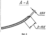
Этот технический результат достигается следующим образом. По предлагаемому способу предварительно проводят формообразование отдельных деталей, в процессе которого для компенсации сварочных деформаций от усадки сварных швов детали из стали или титана изготавливают с недогибом кромок от их теоретической формы, а детали из алюминия - с перегибом кромок по всему периметру деталей в зоне действия последующих сварочных деформаций с шириной, равной 8-10 S, где S - толщина деталей. Предварительное формообразование листовых деталей осуществляют на прессовом оборудовании с использованием универсальной оснастки методом последовательных локальных нажатий или ротационно-локальным способом на опорном деформирующем элементе с последующим соединением согнутых деталей в единую конструкцию преимущественно с помощью сварки. Кромки деталей из стали и титанового сплава выполняют с недогибом, а из алюминиевых сплавов - с перегибом, т.к. на первых из-за их невысокой теплопроводности при сварке образуются так называемые «домики», а на вторых - вследствие их высокой теплопроводности при сварке появляются так называемые «провалы». Стыковые и пазовые кромки боковых лепестков, стыкуемых с донышком, также изготавливают с недогибом (перегибом). Указанные дефекты, вызванные остаточными сварочными деформациями от усадки сварных швов и прогиба стыкуемых кромок заготовок, компенсируются за счет предварительного недогиба для одних деталей и перегиба для других.This technical result is achieved as follows. According to the proposed method, preliminary shaping of individual parts is carried out, during which, to compensate for welding deformations from shrinkage of welds, steel or titanium parts are made with a curvature of edges from their theoretical shape, and aluminum parts are made with bending of edges around the entire perimeter of the parts in the area of subsequent welding strains with a width equal to 8-10 S, where S is the thickness of the parts. Preliminary shaping of sheet parts is carried out on press equipment using universal tooling by the method of successive local pressing or by rotational-local method on a supporting deforming element with the subsequent connection of bent parts into a single structure, mainly by welding. The edges of parts made of steel and titanium alloy are bent, and from aluminum alloys, they are bent, because on the former, due to their low thermal conductivity, so-called “houses” are formed during welding, and on the latter, due to their high thermal conductivity, so-called “dips” appear during welding. The butt and groove edges of the side lobes mating with the bottom are also made with inflection (kink). These defects caused by residual welding deformation from shrinkage of the welds and deflection of the abutting edges of the workpieces are compensated by preliminary inflection for some parts and kink for others.
В частном случае для устранения остаточных перемещений и напряжений свариваемые кромки деталей зоны сварного соединения предварительно раскатывают. В этом случае зона оболочки в месте будущего сварного соединения перемещается (недогиб/перегиб) на величину 0,5 S, которая численно может быть равна аксиальному или радиальному перемещению в зоне сварного шва. Профиль поверхности кромки является зеркальным отражением профиля оболочки после сварки. В этом случае сварочные деформации изгиба кромки оболочки приведут к компенсации деформированной зоны и остаточные перемещения будут близки к нулю. Для компенсации продольной сварочной деформации 3/4 средней части кромки лепестков предварительно раскатывают роликом, которым создают давление, рассчитываемое по эмпирической формуле:In a particular case, to eliminate residual displacements and stresses, the welded edges of the parts of the welded joint zone are pre-rolled. In this case, the sheath zone in the place of the future welded joint moves (inflection / kink) by a value of 0.5 S, which can be numerically equal to the axial or radial movement in the weld zone. The edge surface profile is a mirror image of the shell profile after welding. In this case, the welding deformation of the bending of the edge of the shell will lead to compensation of the deformed zone and the residual displacements will be close to zero. To compensate for longitudinal welding deformation, 3/4 of the middle part of the edge of the petals is pre-rolled with a roller, which creates pressure calculated by the empirical formula:
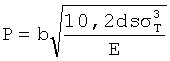
где b - ширина роликов, d - диаметр роликов, s - толщина оболочки, σT, Е - предел текучести и модуль упругости прокатываемого материала.where b is the width of the rollers, d is the diameter of the rollers, s is the shell thickness, σ T , E is the yield strength and elastic modulus of the rolled material.
В другом частном случае детали - донышки изготавливают увеличенной высоты на величину поперечной усадки сварного шва и его вертикального смещения, а кромку донышка по периметру формообразуют с перегибом (недогибом) в зависимости от материала на величину, равную 1/2 разницы между номинальным и теоретическим диаметрами донышка. В известных решениях устранение вертикальной составляющей в зоне сварного шва на оболочке может производиться введением припуска.In another particular case, the parts - bottoms are made of increased height by the amount of transverse shrinkage of the weld and its vertical displacement, and the edge of the bottom along the perimeter is formed with an inflection (inflection) depending on the material by an amount equal to 1/2 the difference between the nominal and theoretical diameters of the bottom . In known solutions, the elimination of the vertical component in the zone of the weld on the shell can be made by introducing an allowance.
Еще в одном частном случае сварку деталей выполняют с внутренней вогнутой стороны оболочки от середины кромки к ее концам.In another particular case, the welding of parts is performed from the inner concave side of the shell from the middle of the edge to its ends.
Отмеченные закономерности и предлагаемый способ были апробированы в рамках опытно-конструкторских работ (ОКР «Шельф») и на заказе «Тритон-НН».The noted patterns and the proposed method were tested in the framework of experimental design work (ROC "Shelf") and on the order of "Triton-NN".
Сущность предлагаемого способа формообразования листовых конструкций с двоякой кривизной поверхности поясняется прилагаемыми чертежами:The essence of the proposed method of forming sheet structures with a double curvature of the surface is illustrated by the accompanying drawings:
фиг.1 - общий вид торосферического днища с двоякой кривизной поверхности;figure 1 - General view of the torospherical bottom with a double curvature of the surface;
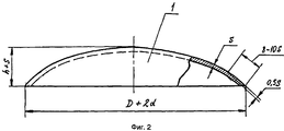
фиг.2 - наиболее выпуклый центральный купол торосферического днища;figure 2 - the most convex central dome of the torospherical bottom;
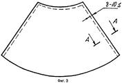
фиг.3 - боковой лепесток торосферического днища;figure 3 - side lobe of the torospherical bottom;
фиг.4 - сечение А-А фиг.3;figure 4 - section aa figure 3;
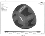
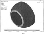
фиг.5 - расчетное компьютерное определение ожидаемой деформации при сварке лепестков;5 is a calculated computer determination of the expected deformation when welding the petals;
фиг.6 - расчетное компьютерное определение ожидаемой деформации при сварке донышка и кольцевого пояса, состоящего из сваренных лепестков.6 is a calculated computer definition of the expected deformation when welding the bottom and the annular belt, consisting of welded petals.
На чертежах приняты следующие обозначения: s - толщина штампуемой детали, h - глубина штампуемого донышка, D - диаметр донышка, d - припуск по периметру штампуемого донышка.The following notations are used in the drawings: s - thickness of the stamped part, h - depth of the stamped bottom, D - diameter of the bottom, d - allowance around the perimeter of the stamped bottom.
Наибольшие утонения, возникающие в деталях при деформировании, имеют примерно одинаковые значения. Величины утонений листовых элементов конструкции и граничные значения деформирования определяются в зависимости от габаритных размеров заготовок и относительных радиусов заданной кривизны и марки штампуемого материала.The greatest thinning occurring in parts during deformation have approximately the same values. Thinning values of sheet structural elements and boundary deformation values are determined depending on the overall dimensions of the workpieces and the relative radii of the given curvature and the type of stamped material.
При этом, как показали последние исследования, в частности по ОКР «Шельф», выполняемой по федеральной целевой программе (ФЦП) «Национальная технологическая база» на 2007-2011 годы, геометрия и утонения заготовок находились в пределах заданных допусков на конструкцию.At the same time, as recent studies have shown, in particular on the Shelf design and development work carried out under the National Technological Base federal target program (FTP) for 2007-2011, the geometry and thinning of workpieces were within the specified design tolerances.
Наиболее выпуклая деталь сварной листовой конструкции, получаемой деформированием, в рассматриваемом примере - центральный сферический купол (фиг.1, поз.1 - донышко), предусмотрена с недогибом по стыкуемым кромкам на величину ее последующей поперечной усадки в результате сварки (фиг.2, 3), которая определяется расчетным путем по ОСТ5.9807-93 и на основании опыта изготовления подобных конструкций.The most convex part of the welded sheet structure obtained by deformation, in this example, the central spherical dome (Fig. 1, pos. 1 - bottom), is provided with inflection along the abutting edges by the value of its subsequent transverse shrinkage as a result of welding (Fig. 2, 3 ), which is determined by calculation according to OST5.9807-93 and on the basis of experience in the manufacture of such structures.
Как показал расчет, выполненный с использованием программного пакета ANSYS (фиг.5 и 6), и опыт изготовления подобных конструкций, сварку необходимо осуществлять первоначально с внутренней стороны, т.е. по вогнутой части, причем сварку ведут от середины кромки к ее концам, что уменьшает общую усадку конструкции.As shown by the calculation performed using the ANSYS software package (FIGS. 5 and 6) and the experience of manufacturing such structures, welding must be carried out initially from the inside, i.e. along the concave part, and welding is carried out from the middle of the edge to its ends, which reduces the overall shrinkage of the structure.
С учетом вышеперечисленных основных положений при изготовлении такого рода листовая торосферическая конструкция была изготовлена на предприятии ОАО «Северная верфь» в рамках заказа «Тритон-НН». Формообразование донышка R=2000 мм, толщиной t=10 мм из сплава 1561 с допуском ΔR=4 мм (для контроля по шаблону) и шести торосферических лепестков толщиной t=10 мм с допуском по толщине Δ=3 мм на каждой стык проводили на прессе «Клиринг» усилием 2500 кН. При этом удалось получить требуемое качество гибки, приемлемые отклонения формы и размеров, что позволило собранной конструкции успешно пройти гидравлические испытания.Taking into account the abovementioned main provisions in the manufacture of this kind of sheet torospherical structure was manufactured at the enterprise of OJSC Severnaya Verf in the framework of the Triton-NN order. The shaping of the bottom R = 2000 mm, thickness t = 10 mm from alloy 1561 with a tolerance of ΔR = 4 mm (for pattern control) and six torospherical petals with a thickness of t = 10 mm with a tolerance of thickness Δ = 3 mm on each joint was carried out on a press Clearing with an effort of 2500 kN. At the same time, it was possible to obtain the required bending quality, acceptable deviations in shape and size, which allowed the assembled structure to successfully pass hydraulic tests.
Claims (8)

b - ширина роликов, d - диаметр роликов, s - толщина оболочки, σТ, Е - предел текучести и модуль упругости прокатываемого материала.3. The method according to claim 1, characterized in that 3/4 of the middle part of the edge of the petals is pre-rolled with a roller, which creates a pressure calculated by the formula
b is the width of the rollers, d is the diameter of the rollers, s is the shell thickness, σ T , E is the yield strength and elastic modulus of the rolled material.
b - ширина роликов, d - диаметр роликов, s - толщина оболочки, σТ, Е - предел текучести и модуль упругости прокатываемого материала.7. The method according to claim 3, characterized in that 3/4 of the middle part of the edge of the petals is pre-rolled with a roller, which creates a pressure calculated by the formula
b is the width of the rollers, d is the diameter of the rollers, s is the shell thickness, σ T , E is the yield strength and elastic modulus of the rolled material.
Priority Applications (1)
| Application Number | Priority Date | Filing Date | Title |
|---|---|---|---|
| RU2009128404/02A RU2419503C2 (en) | 2009-07-22 | 2009-07-22 | Method of producing bicurved surface shells (versions) |
Applications Claiming Priority (1)
| Application Number | Priority Date | Filing Date | Title |
|---|---|---|---|
| RU2009128404/02A RU2419503C2 (en) | 2009-07-22 | 2009-07-22 | Method of producing bicurved surface shells (versions) |
Publications (2)
| Publication Number | Publication Date |
|---|---|
| RU2009128404A RU2009128404A (en) | 2011-01-27 |
| RU2419503C2 true RU2419503C2 (en) | 2011-05-27 |
Family
ID=44735021
Family Applications (1)
| Application Number | Title | Priority Date | Filing Date |
|---|---|---|---|
| RU2009128404/02A RU2419503C2 (en) | 2009-07-22 | 2009-07-22 | Method of producing bicurved surface shells (versions) |
Country Status (1)
| Country | Link |
|---|---|
| RU (1) | RU2419503C2 (en) |
Citations (1)
| Publication number | Priority date | Publication date | Assignee | Title |
|---|---|---|---|---|
| US4176713A (en) * | 1976-02-12 | 1979-12-04 | Helmut Fisher | Plate-type heat exchanger |
-
2009
- 2009-07-22 RU RU2009128404/02A patent/RU2419503C2/en not_active IP Right Cessation
Patent Citations (1)
| Publication number | Priority date | Publication date | Assignee | Title |
|---|---|---|---|---|
| US4176713A (en) * | 1976-02-12 | 1979-12-04 | Helmut Fisher | Plate-type heat exchanger |
Non-Patent Citations (1)
| Title |
|---|
| МОШНИН Е.Н. Технология штамповки крупногабаритных деталей. - М.: Машиностроение, 1973, с.9, рис.2. * |
Also Published As
| Publication number | Publication date |
|---|---|
| RU2009128404A (en) | 2011-01-27 |
Similar Documents
| Publication | Publication Date | Title |
|---|---|---|
| CA2879808C (en) | Press-forming tool and method for manufacturing press-formed product | |
| JP6146480B2 (en) | Steel plate material manufacturing method and manufacturing apparatus | |
| KR20210118792A (en) | Manufacturing method of thickness-varied metal plate, manufacturing method of pressed part, and processing machine | |
| JP6132030B2 (en) | Manufacturing method of forged crankshaft | |
| JP6245369B2 (en) | Manufacturing method of forged crankshaft | |
| KR20140131391A (en) | Device and method for producing closed-cross-section-structure component | |
| CN107427901B (en) | Manufacturing method of forged crankshaft | |
| RU2510784C1 (en) | Method of making high-pressure welded vessels | |
| RU2419503C2 (en) | Method of producing bicurved surface shells (versions) | |
| JP6287631B2 (en) | Manufacturing method of forged crankshaft | |
| WO2016186165A1 (en) | Forged crankshaft manufacturing device and manufacturing method | |
| RU2414980C2 (en) | Method of producing bicurved surface sheet structure | |
| JP6439863B2 (en) | Manufacturing method of forged crankshaft | |
| JP2025091461A (en) | Metal can manufacturing method and die set | |
| RU2170193C1 (en) | Fuel tank head and method of its manufacture | |
| Vasechkin et al. | Increasing the strength of welded thin-walled axisymmetric vessels made of corrosion-resistant steel | |
| JP4248788B2 (en) | Forming roll and forming method | |
| Mohammed | The influence of different forming techniques on the performance and outcomes of the deep drawing process for intricate geometries | |
| US10828693B2 (en) | Apparatus for manufacturing forged crankshaft | |
| SU1726094A1 (en) | Method of making semicylindrical parts | |
| JP7541242B2 (en) | Blank, method for setting flow control area, method for designing blank, and method for manufacturing blank | |
| CN118023859B (en) | A method for forming a large-size ultra-high-strength steel deep-cavity integral head | |
| SU978996A1 (en) | Method of forged and welded articles | |
| RU2684332C2 (en) | Method of manufacturing hollow products | |
| RU2471585C1 (en) | Method of making thin-wall asymmetric bicurvature shells with flange |
Legal Events
| Date | Code | Title | Description |
|---|---|---|---|
| MM4A | The patent is invalid due to non-payment of fees |
Effective date: 20170723 |