RU2415518C2 - Led-based illuminator - Google Patents
Led-based illuminator Download PDFInfo
- Publication number
- RU2415518C2 RU2415518C2 RU2008120669/07A RU2008120669A RU2415518C2 RU 2415518 C2 RU2415518 C2 RU 2415518C2 RU 2008120669/07 A RU2008120669/07 A RU 2008120669/07A RU 2008120669 A RU2008120669 A RU 2008120669A RU 2415518 C2 RU2415518 C2 RU 2415518C2
- Authority
- RU
- Russia
- Prior art keywords
- led light
- color
- light source
- temperature
- led
- Prior art date
Links
Images
Classifications
-
- H—ELECTRICITY
- H05—ELECTRIC TECHNIQUES NOT OTHERWISE PROVIDED FOR
- H05B—ELECTRIC HEATING; ELECTRIC LIGHT SOURCES NOT OTHERWISE PROVIDED FOR; CIRCUIT ARRANGEMENTS FOR ELECTRIC LIGHT SOURCES, IN GENERAL
- H05B45/00—Circuit arrangements for operating light-emitting diodes [LED]
- H05B45/20—Controlling the colour of the light
- H05B45/22—Controlling the colour of the light using optical feedback
-
- H—ELECTRICITY
- H05—ELECTRIC TECHNIQUES NOT OTHERWISE PROVIDED FOR
- H05B—ELECTRIC HEATING; ELECTRIC LIGHT SOURCES NOT OTHERWISE PROVIDED FOR; CIRCUIT ARRANGEMENTS FOR ELECTRIC LIGHT SOURCES, IN GENERAL
- H05B45/00—Circuit arrangements for operating light-emitting diodes [LED]
- H05B45/20—Controlling the colour of the light
- H05B45/28—Controlling the colour of the light using temperature feedback
Abstract
Description
Изобретение относится к светодиодному осветительному устройству, содержащему множество светодиодных источников света различных цветов для получения источника света смешанного цвета. Настоящее изобретение относится также к способу и устройству для управления светодиодным осветительным устройством.The invention relates to an LED lighting device comprising a plurality of LED light sources of various colors to produce a mixed color light source. The present invention also relates to a method and apparatus for controlling an LED lighting device.
Комбинирование разноцветных светодиодов для получения смешанного цвета является обычным способом создания белого или цветного источника света. Полученный источник света определяется рядом параметров, например типом используемых светодиодов, соотношениями цветов, соотношениями драйверов, комбинационными соотношениями и др. Однако с повышением температуры светодиодов во время их работы оптические характеристики светодиодов изменяются: уменьшается интенсивность выходного излучения и смещается пиковая длина волны (длина волны, соответствующая максимуму излучения).Combining multi-colored LEDs to produce a mixed color is the usual way to create a white or color light source. The resulting light source is determined by a number of parameters, for example, the type of LEDs used, color ratios, driver ratios, combination ratios, etc. However, with an increase in the temperature of the LEDs during their operation, the optical characteristics of the LEDs change: the output radiation intensity decreases and the peak wavelength shifts (wavelength, corresponding to the maximum radiation).
Для устранения или снижения остроты данной проблемы были предложены различные устройства управления цветом для компенсации данных изменений в оптических характеристиках светодиодов во время их использования. Примерами устройств или алгоритмов управления цветом являются управление с обратной связью по координатам цветности (color coordinates feedback - CCFB), управление с прямой связью по температуре (temperature feed forward - TFF), управление с обратной связью по потоку (flux feedback - FFB) или комбинация последних двух вариантов управления (FFB+TFF), которая раскрыта, например, в публикации «Обеспечение стабильности цвета свечения в многокристальных светодиодных RGB-модулях с использованием различных контуров управления цветом», P. Deurenberg и др., труды SPIE, том 5941, 59410С (7 сентября 2005 г.).To eliminate or reduce the severity of this problem, various color management devices have been proposed to compensate for these changes in the optical characteristics of LEDs during their use. Examples of devices or color management algorithms are color coordinate feedback (CCFB) control, temperature feed forward (TFF) control, flux feedback (FFB) control, or a combination the last two control options (FFB + TFF), which is disclosed, for example, in the publication “Ensuring the stability of the glow color in multi-chip RGB LED modules using different color control loops”, P. Deurenberg et al., SPIE proceedings, vol. 5941, 59410С (September 7, 2005).
В схеме CCFB светодиоды с фильтрами используются для обеспечения обратной связи по координатам цветности реального источника света смешанного цвета, при этом координаты цвета сравниваются с контрольными или заданными значениями, характеризующими требуемый цвет смешанного цвета. В данном случае управление светодиодами осуществляется в соответствии с полученными разностями.In the CCFB scheme, LEDs with filters are used to provide feedback on the chromaticity coordinates of a real mixed-light source, while the color coordinates are compared with control or setpoints characterizing the desired mixed-color color. In this case, the LEDs are controlled in accordance with the differences obtained.
Считается, что такая система обратной связи может надежно компенсировать температурные эффекты во всех светодиодных устройствах. Однако проведенные в последнее время измерения показывают, что это справедливо не для всякой комбинации светодиод-датчик. В действительности определенные комбинации создают очень нестабильное по цвету выходное излучение, не намного лучшее, чем при отсутствии компенсации. Причина, лежащая в основе неэффективной работы системы обратной связи, заключается в том, что существует несоответствие между чувствительностью датчика и чувствительностью человеческого глаза. То есть цветочувствительность датчика и цветочувствительность человеческого глаза разные. Это означает, что система обратной связи будет точно поддерживать светоотдачу в области датчика, но не в области человеческого глаза. Если бы светодиоды излучали свет с постоянной длиной волны, то компенсировать разницу в чувствительности датчика и чувствительности человеческого глаза было бы просто. Однако для разных длин волн несоответствие между чувствительностью датчика и чувствительностью глаза будет разным, и кроме того, пиковая длина волны светодиода увеличивается с повышением температуры. В частности, в диапазонах длин волн светодиодов, где с увеличением длины волны чувствительность глаза увеличивается, а чувствительность датчика уменьшается, данное несоответствие возрастает и приводит к большим расхождениям в цветопередаче.It is believed that such a feedback system can reliably compensate for temperature effects in all LED devices. However, recent measurements show that this is not true for any combination of LED-sensor. In fact, certain combinations produce a very unstable color output, not much better than in the absence of compensation. The reason underlying the inefficiency of the feedback system is that there is a mismatch between the sensitivity of the sensor and the sensitivity of the human eye. That is, the color sensitivity of the sensor and the color sensitivity of the human eye are different. This means that the feedback system will accurately maintain light output in the sensor area, but not in the human eye. If the LEDs emitted light with a constant wavelength, it would be easy to compensate for the difference in the sensitivity of the sensor and the sensitivity of the human eye. However, for different wavelengths, the mismatch between the sensitivity of the sensor and the sensitivity of the eye will be different, and in addition, the peak wavelength of the LED increases with increasing temperature. In particular, in the wavelength ranges of LEDs, where with an increase in the wavelength, the sensitivity of the eye increases and the sensitivity of the sensor decreases, this discrepancy increases and leads to large differences in color reproduction.
Целью настоящего изобретения является решение данной проблемы и создание усовершенствованного, более стабильного по цвету светодиодного осветительного устройства.The aim of the present invention is to solve this problem and create an improved, more color-stable LED lighting device.
Эта и другие цели, которые будут понятны из следующего описания, достигаются посредством создания светодиодного осветительного устройства, способа и устройства для управления светодиодным осветительным устройством в соответствии с прилагаемой формулой изобретения.This and other objectives, which will be clear from the following description, are achieved by creating an LED lighting device, method and device for controlling an LED lighting device in accordance with the attached claims.
В соответствии с одним аспектом настоящего изобретения создано светодиодное осветительное устройство, включающее множество светодиодных источников света различных цветов для получения света смешанного цвета и устройство для управления светодиодными источниками света в соответствии с разностями между заданными значениями, характеризующими свет смешанного цвета, имеющий требуемый цвет, и первыми управляющими данными, характеризующими цвет света смешанного цвета, создаваемого светодиодными источниками света, при этом первые управляющие данные обеспечиваются с помощью по меньшей мере одного цветового датчика, светодиодное осветительное устройство отличается устройством для получения температуры каждого светодиодного источника света и устройством для компенсации заданных значений в соответствии со вторыми управляющими данными, включающими температуры светодиодных источников света.In accordance with one aspect of the present invention, there is provided an LED lighting device comprising a plurality of LED light sources of various colors to produce mixed color light and a device for controlling LED light sources in accordance with differences between predetermined values characterizing mixed color light having the desired color and the first control data characterizing the color of light of a mixed color created by LED light sources, while the first control guides data provided by at least one color sensor, LED lighting device is characterized apparatus for obtaining temperature of each LED light source and a device for compensating set point values in accordance with second control data including the LED light source temperatures.
В результате компенсации каждого заданного значения в соответствии с температурой соответствующего светодиодного источника света можно вычислять смещения пиковых длин волн при изменении температуры светодиодных источников света, посредством чего получается более стабильное по цвету и надежное осветительное устройство.As a result of the compensation of each set value in accordance with the temperature of the corresponding LED light source, it is possible to calculate the displacement of the peak wavelengths with a change in the temperature of the LED light sources, whereby a more color stable and reliable lighting device is obtained.
Следует отметить, что пример вычисления изменений температуры в светодиодном осветительном устройстве с функцией типа CCFB известен из документа «Получение белого цвета на основе красного, зеленого и голубого светодиодов: проблемы и управление», Muthu и др. (2002), в котором коэффициент усиления сигналов обратной связи корректируется в зависимости от температуры теплоотвода (для учета изменений температуры). Данный подход отличается от устройства в соответствии с настоящим изобретением, в котором регулируются не сами сигналы, а заданные значения, с которыми сравниваются сигналы обратной связи. Кроме того, устройство, раскрытое в вышеуказанном документе, установлено в области человека, тогда как устройство в соответствии с настоящим изобретением установлено в области датчика.It should be noted that an example of calculating temperature changes in an LED lighting device with a CCFB type function is known from the document “Getting White Color Based on Red, Green, and Blue LEDs: Problems and Management”, Muthu et al. (2002), in which the signal gain feedback is adjusted depending on the temperature of the heat sink (to account for temperature changes). This approach differs from the device in accordance with the present invention, in which not the signals themselves are regulated, but the setpoints with which the feedback signals are compared. In addition, the device disclosed in the above document is installed in the human area, while the device in accordance with the present invention is installed in the sensor area.
Предпочтительно, если вторые управляющие данные включают также контрольную температуру светодиодного источника света для каждого светодиодного источника света, посредством чего разница между полученной температурой светодиодного источника света и контрольной температурой светодиодного источника света является мерой величины смещения пиковой длины волны для светодиодного источника света. Так как данное смещение является постоянным в широком диапазоне температур, можно определить пиковую длину волны в данный момент, в результате чего данная информация используется для регулирования заданных значений.Preferably, the second control data also includes the control temperature of the LED light source for each LED light source, whereby the difference between the obtained temperature of the LED light source and the control temperature of the LED light source is a measure of the peak wavelength offset for the LED light source. Since this bias is constant over a wide temperature range, it is possible to determine the peak wavelength at a given moment, as a result of which this information is used to control the setpoints.
Предпочтительно, если вторые управляющие данные включают также данные, характеризующие чувствительность датчика (датчиков) для разных пиковых длин волн, а также данные, характеризующие спектры светодиодных источников света, на основе которых соответственно можно регулировать заданные значения.Preferably, if the second control data also includes data characterizing the sensitivity of the sensor (s) for different peak wavelengths, as well as data characterizing the spectra of LED light sources, based on which, respectively, you can adjust the set values.
Для получения температуры каждого светодиодного источника света средство получения данных может включать датчик температуры, приспособленный для измерения температуры теплоотвода, размещающего светодиодные источники света. В одном варианте осуществления средство получения данных включает также средство для вычисления температур светодиодных источников света на основе по меньшей мере измеренной температуры теплоотвода и термической модели множества светодиодных источников света.To obtain the temperature of each LED light source, the data acquisition means may include a temperature sensor adapted to measure the temperature of the heat sink accommodating the LED light sources. In one embodiment, the data acquisition means also includes means for calculating the temperatures of the LED light sources based on at least the measured heat sink temperature and the thermal model of the plurality of LED light sources.
Кроме того, по меньшей мере одним цветовым датчиком могут быть фотодиоды с фильтрами, предпочтительно один датчик для каждого цвета светодиодного источника света, для определения цвета света, создаваемого светодиодными источниками света.In addition, the at least one color sensor may be filter photodiodes, preferably one sensor for each color of the LED light source, to determine the color of the light generated by the LED light sources.
В соответствии с другим аспектом настоящего изобретения создан способ управления светодиодным осветительным устройством, включающим множество светодиодных источников света различных цветов для получения света смешанного цвета, при этом способ включает управление светодиодными источниками света в соответствии с разностями между заданными значениями, характеризующими свет смешанного цвета, имеющий требуемый цвет, и первыми управляющими данными, характеризующими цвет света смешанного цвета, создаваемый с помощью светодиодных источников света, при этом первые управляющие данные обеспечиваются с помощью по меньшей мере одного цветового датчика, данный способ отличается получением температуры каждого светодиодного источника света и компенсацией заданных значений в соответствии со вторыми управляющими данными, включающими температуры светодиодных источников света. Данный способ обладает теми же преимуществами, что и рассмотренный ранее аспект настоящего изобретения.In accordance with another aspect of the present invention, there is provided a method of controlling an LED lighting device including a plurality of LED light sources of various colors to produce mixed color light, the method including controlling the LED light sources in accordance with differences between predetermined values characterizing mixed color light having the desired color, and the first control data characterizing the color of light of a mixed color created using LED sources Ikov beam, wherein the first control data being provided by at least one color sensor, the method characterized by obtaining temperature of each LED light source and the compensated set point values in accordance with second control data including the LED light source temperatures. This method has the same advantages as the previously discussed aspect of the present invention.
В соответствии с еще одним аспектом настоящего изобретения создано устройство управления светодиодным осветительным устройством, включающим множество светодиодных источников света различных цветов для получения света смешанного цвета, при этом данное устройство содержит устройство управления светодиодными источниками света в соответствии с разностями между заданными значениями, характеризующими свет смешанного цвета, имеющий требуемый цвет, и первыми управляющими данными, характеризующими цвет света смешанного цвета, создаваемый с помощью светодиодных источников света, при этом первые управляющие данные обеспечиваются с помощью по меньшей мере одного цветового датчика, данное устройство отличается средством для получения температуры каждого светодиодного источника света и средством для компенсации заданных значений в соответствии со вторыми управляющими данными, включающими температуры светодиодных источников света. Данное устройство управления обладает теми же преимуществами, что и ранее рассмотренные аспекты настоящего изобретения.In accordance with yet another aspect of the present invention, there is provided a LED lighting device control device including a plurality of LED light sources of various colors to produce mixed color light, the device comprising a LED light source control device in accordance with differences between predetermined values characterizing mixed color light having the desired color, and the first control data characterizing the color of the light of mixed color, are created th using LED light sources, while the first control data is provided using at least one color sensor, this device is distinguished by means for obtaining the temperature of each LED light source and means for compensating the set values in accordance with the second control data including the temperature of the LED sources Sveta. This control device has the same advantages as previously discussed aspects of the present invention.
Далее эти и другие аспекты настоящего изобретения будут описаны более подробно со ссылкой на прилагаемые чертежи, иллюстрирующие предпочтительный в данный момент вариант осуществления настоящего изобретения.These and other aspects of the present invention will now be described in more detail with reference to the accompanying drawings, illustrating the currently preferred embodiment of the present invention.
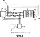
Фиг.1 изображает блок-схему светодиодного осветительного устройства с функцией CCFB в соответствии с существующим уровнем техники,Figure 1 depicts a block diagram of a LED lighting device with CCFB function in accordance with the existing level of technology,
фиг.2 изображает блок-схему, иллюстрирующую светодиодное осветительное устройство в соответствии с вариантом осуществления настоящего изобретения.2 is a block diagram illustrating an LED lighting device according to an embodiment of the present invention.
Фиг.1 изображает блок-схему светодиодного осветительного устройства 10 в соответствии с известным уровнем техники. Светодиодное осветительное устройство данного типа раскрыто, например, в вышеуказанной публикации «Обеспечение стабильности цвета свечения в многокристальных светодиодных RGB-модулях с использованием различных контуров управления цветом», P. Deurenberg и др., труды SPIE, том 5941, 59410С (7 сентября 2005 г.).Figure 1 depicts a block diagram of a
Светодиодное осветительное устройство 10 содержит светодиодный светильник 12, который в свою очередь содержит один светодиодный источник света 14а, включающий светодиоды, приспособленные для излучения красного света, один светодиодный источник света 14b, включающий светодиоды, приспособленные для излучения зеленого света, и один светодиодный источник света 14с, включающий светодиоды, приспособленные для излучения синего света. Каждый светодиодный источник света 14 соединен с соответствующим драйвером 16 для возбуждения светодиодного источника света. Светодиодное осветительное устройство 10 может, например, создавать белый свет посредством смешивания выходных излучений различных светодиодных источников света 14 и может быть использовано для освещения или подсветки. Светодиодным осветительным устройством 10 может быть также светодиодное осветительное устройство переменного цвета.The
Светодиодное осветительное устройство 10 содержит также интерфейс пользователя 18 и калибровочную матрицу 20. Входные данные пользователя, указывающие требуемую интенсивность излучения в люменах и цвет светодиодного светильника 12, вводятся через интерфейс пользователя 18. Входные данные пользователя могут, например, устанавливаться в параметрах x, y, L CIE, характеризующих определенную позицию (точку цветности) на графике цветности CIE 1931. Входные данные пользователя передаются в калибровочную матрицу 20, которая вычисляет номинальные рабочие циклы для каждого цвета R, G, B для выбранной точки цветности (т.е. входные данные пользователя преобразуются из области пользователя в область исполнительного механизма).The
Для реализации функции обратной связи по координатам цветности светодиодное осветительное устройство 10 содержит также трехцветные датчики 22а-22с, контрольный блок цвета 24, блок сравнения 26 и пропорционально-интегрально-дифференциальные (ПИД) регуляторы 28а-28с.To implement the feedback function for color coordinates, the
Каждый датчик 22а-22с связан с соответствующим светодиодным источником света 14а-14с. Таким образом, датчик 22а приспособлен для восприятия красного цвета, датчик 22b приспособлен для восприятия зеленого цвета, и датчик 22с приспособлен для восприятия синего цвета. Цветовыми датчиками 22 могут быть, например, фотодиоды с фильтрами.Each
При работе светодиодного осветительного устройства 10 датчики 22 преобразуют свет смешанного цвета, создаваемый светодиодным светильником 12, в сигналы трех датчиков или сигналы обратной связи (первые управляющие данные), соответствующие красному, зеленому и синему цвету соответственно. Сигналы датчиков находятся в области датчиков.When the
Затем эти сигналы датчиков (характеризующие реальный цвет) сравниваются с заданными значениями (характеризующими требуемый цвет), обеспечиваемыми контрольным блоком цвета 28, который в свою очередь вычисляет данные заданные значения на основе входных данных, полученных из калибровочной матрицы 20. То есть контрольный блок 28 преобразует номинальные рабочие циклы (в области исполнительного механизма) из калибровочной матрицы 20 в заданные значения (в области датчика) при определенной контрольной температуре. Заданные значения сравниваются с соответствующими значениями обратной связи для каждого цвета в блоке сравнения 26, и полученные в результате разности для каждого цвета R, G, B поступают в ПИД-регуляторы 28. ПИД-регуляторы 28 в свою очередь изменяют входные данные, которые подаются в драйверы светодиодов 16а-16с, в соответствии с полученными разностями. Это обеспечивает регулирование красных, зеленых и синих светодиодных источников света 14а-14с таким образом, чтобы выходное излучение светодиодного светильника 12 имело требуемый цвет (т.е. так, чтобы свести к нулю несоответствие между заданными значениями и значениями обратной связи при установившихся условиях). Следует отметить, что перед поступлением в светодиодный светильник выходные сигналы ПИД-регуляторов преобразуются из области датчиков в область исполнительного механизма (рабочие циклы) и усиливаются с помощью выходных сигналов из калибровочной матрицы (т.е. номинальными рабочими циклами). Как указано выше, функция CCFB может повысить стабильность цвета светодиодного осветительного устройства, однако не для каждой комбинации светодиод-датчик.Then these sensor signals (characterizing the actual color) are compared with the set values (characterizing the desired color) provided by the color control unit 28, which in turn calculates the data set values based on input data obtained from the
Фиг.2 изображает блок-схему светодиодного осветительного устройства в соответствии с вариантом осуществления настоящего изобретения. Разница между устройством в соответствии с известным уровнем техники по фиг.1 и устройством по фиг.2 заключается в том, что светодиодное осветительное устройство 10 по фиг.2 дополнительно включает также функцию управления с прямой связью по температуре (TFF) для дополнительного повышения стабильности цвета. Функция TFF здесь реализована с помощью датчика температуры 30, вычислительного блока 32 и контрольного блока 34.Figure 2 depicts a block diagram of an LED lighting device in accordance with an embodiment of the present invention. The difference between the device in accordance with the prior art of FIG. 1 and the device of FIG. 2 is that the
Датчик температуры 30 установлен на теплоотводе 36, при этом теплоотвод 36 также размещает светодиодные источники света 14. При работе датчик температуры 30 измеряет температуру теплоотвода. Затем результат измерения температуры поступает в вычислительный блок 32, который на основе температуры теплоотвода, а также термической модели светодиодных источников света и входных электрических токов светодиодных источников света вычисляет температуру (а именно, температуру перехода) для каждого светодиодного источника света 14а-14с. Температурой перехода является температура активного слоя внутри светодиода.The temperature sensor 30 is installed on the heat sink 36, while the heat sink 36 also places the LED light sources 14. In operation, the temperature sensor 30 measures the temperature of the heat sink. Then, the temperature measurement result is supplied to the computing unit 32, which calculates the temperature (namely, the transition temperature) for each
Затем данные температуры перехода (Tred, Tgreen и Tblue) поступают в контрольный блок 34. Так же как и контрольный блок 24 по фиг.1, контрольный блок 34 по фиг.2 содержит заданные значения, вычисленные на основе входных данных, полученных из калибровочной матрицы 20. Кроме того, контрольный блок 34 содержит контрольную температуру перехода для каждого светодиодного источника света 14, в результате чего разность между температурой перехода в данный момент и контрольной температурой перехода является мерой величины смещения пиковой длины волны. Так как данное смещение является постоянным в широком диапазоне температур, можно определить пиковую длину волны в данный момент для каждого светодиодного источника света.Then, the transition temperature data (T red , T green, and T blue ) is supplied to the control unit 34. As well as the
Эта информация (вторые управляющие данные) затем используется в блоке 34 для компенсации заданных значений для вычисления смещений пиковых длин волн при изменении температуры светодиодных источников света. То есть заданные значения пересчитываются для оцененной пиковой длины волны в данный момент. Для выполнения такого пересчета для каждого цвета светодиодного источника света требуются смещение пиковой длины волны, данные, относящиеся к чувствительности датчиков и спектру светодиодного источника света, оценка пиковой длины волны при контрольной температуре и термическая модель устройства. Таким образом, когда заданные значения, характеризующие требуемое выходное излучение светодиодного светильника 12, сравниваются в блоке сравнения 26 с выходными данными светодиодного светильника в данный момент, заданные значения уже компенсированы относительно смещения пиковой длины волны светодиодных источников света 14.This information (second control data) is then used in block 34 to compensate for the setpoints to calculate peak wavelength shifts when the temperature of the LED light sources changes. That is, the setpoints are recalculated for the estimated peak wavelength at the moment. To perform such a conversion, for each color of the LED light source, a peak wavelength offset, data related to the sensitivity of the sensors and the spectrum of the LED light source, an estimate of the peak wavelength at a reference temperature and a thermal model of the device are required. Thus, when the target values characterizing the desired output radiation of the
Следует отметить, что данная компенсация должна также применяться при преобразовании из области датчика в область исполнительного механизма (т.е. между ПИД-регуляторами и светодиодным светильником), но в обратном варианте. Кроме того, температуры из вычислительного блока 32 проходят также в калибровочную матрицу 20 для учета смещений пиковых длин волн.It should be noted that this compensation should also be applied when converting from the sensor area to the area of the actuator (i.e. between the PID controllers and the LED lamp), but in the opposite way. In addition, temperatures from computing unit 32 also pass into
Таким образом, светодиодное осветительное устройство в соответствии с существующим в данный момент вариантом осуществления настоящего изобретения использует алгоритм управления цветом, включающий как CCFB, так и TFF. Как было указано выше, такая компенсация обеспечивает светодиодное осветительное устройство с более высокой стабильностью цвета. При использовании алгоритма управления цветом CCFB+TFF в светодиодном RGB-светильнике (как указано выше) стабильность цвета повышается приблизительно на два пункта по сравнению со светильником, в котором используется только CCFB, как показано ниже в таблице. Еще более существенный эффект достигается при использовании алгоритма управления цветом CCFB+TFF в светодиодном AGB-светильнике, в котором стабильность цвета повышается на 24 пункта по сравнению с вариантом использования алгоритма управления цветом CCFB.Thus, the LED lighting device in accordance with the currently existing embodiment of the present invention uses a color management algorithm including both CCFB and TFF. As mentioned above, such compensation provides an LED lighting device with higher color stability. When using the CCFB + TFF color management algorithm in an RGB LED fixture (as indicated above), color stability is increased by about two points compared to a fixture that uses only CCFB, as shown in the table below. An even more significant effect is achieved by using the CCFB + TFF color management algorithm in an AGB LED luminaire, in which color stability is increased by 24 points compared to the CCFB color management algorithm.
(ΔT=73 K)Δu′v ′
(ΔT = 73 K)
Специалистам в данной области техники понятно, что настоящее изобретение никак не ограничено предпочтительными вариантами осуществления, описанными выше. Напротив, возможно множество модификаций и изменений без отхода от объема прилагаемой формулы изобретения. Например, устройство и способ в соответствии с настоящим изобретением могут быть использованы для различных комбинаций светодиодов, таких как RGB, AGB, RAGB, светодиоды с люминофорами и др.Those skilled in the art will appreciate that the present invention is in no way limited to the preferred embodiments described above. On the contrary, many modifications and changes are possible without departing from the scope of the attached claims. For example, the device and method in accordance with the present invention can be used for various combinations of LEDs, such as RGB, AGB, RAGB, LEDs with phosphors, etc.
Claims (20)
Applications Claiming Priority (2)
| Application Number | Priority Date | Filing Date | Title |
|---|---|---|---|
| EP05109999.2 | 2005-10-26 | ||
| EP05109999 | 2005-10-26 |
Publications (2)
| Publication Number | Publication Date |
|---|---|
| RU2008120669A RU2008120669A (en) | 2009-12-10 |
| RU2415518C2 true RU2415518C2 (en) | 2011-03-27 |
Family
ID=37746594
Family Applications (1)
| Application Number | Title | Priority Date | Filing Date |
|---|---|---|---|
| RU2008120669/07A RU2415518C2 (en) | 2005-10-26 | 2006-10-16 | Led-based illuminator |
Country Status (8)
| Country | Link |
|---|---|
| US (1) | US7804260B2 (en) |
| EP (1) | EP1943880B1 (en) |
| JP (1) | JP5311639B2 (en) |
| KR (1) | KR101300565B1 (en) |
| CN (1) | CN101297604B (en) |
| RU (1) | RU2415518C2 (en) |
| TW (1) | TWI427580B (en) |
| WO (1) | WO2007049180A1 (en) |
Cited By (2)
| Publication number | Priority date | Publication date | Assignee | Title |
|---|---|---|---|---|
| RU2494495C1 (en) * | 2012-03-30 | 2013-09-27 | Федеральное государственное бюджетное образовательное учреждение высшего профессионального образования "Санкт-Петербургский национальный исследовательский университет информационных технологий, механики и оптики" | Multielement colour radiation source |
| WO2017111666A1 (en) * | 2015-12-25 | 2017-06-29 | Александр ЧАРГАЗИЯ | Bag with multimedia device |
Families Citing this family (47)
| Publication number | Priority date | Publication date | Assignee | Title |
|---|---|---|---|---|
| KR20070077719A (en) | 2006-01-24 | 2007-07-27 | 삼성전기주식회사 | Driver of color led |
| WO2008078240A1 (en) * | 2006-12-20 | 2008-07-03 | Philips Intellectual Property & Standards Gmbh | Adjusting a driving signal for solid-state lighting devices |
| KR20080094394A (en) * | 2007-04-20 | 2008-10-23 | 삼성전자주식회사 | Method for driving light source, driving circuit for performing the same, light source assembly having the driving circuit and display device having the driving circuit |
| TW201004477A (en) | 2008-06-10 | 2010-01-16 | Microsemi Corp Analog Mixed Si | Color manager for backlight systems operative at multiple current levels |
| WO2010052640A1 (en) | 2008-11-06 | 2010-05-14 | Koninklijke Philips Electronics N.V. | Illumination device |
| US8143791B2 (en) * | 2008-12-12 | 2012-03-27 | Palo Alto Research Center Incorporated | Control system for light-emitting device |
| US8324830B2 (en) | 2009-02-19 | 2012-12-04 | Microsemi Corp.—Analog Mixed Signal Group Ltd. | Color management for field-sequential LCD display |
| EP2449854A1 (en) * | 2009-06-30 | 2012-05-09 | EldoLAB Holding B.V. | Method of configuring an led driver, led driver, led assembly and method of controlling an led assembly |
| US8779685B2 (en) | 2009-11-19 | 2014-07-15 | Intematix Corporation | High CRI white light emitting devices and drive circuitry |
| TWI413446B (en) * | 2010-02-11 | 2013-10-21 | Univ Nat Taiwan | Poly-chromatic light-emitting diode (led) lighting system |
| TWI518736B (en) * | 2010-03-31 | 2016-01-21 | Ats自動模具系統股份有限公司 | Light generator systems and methods |
| US8946998B2 (en) | 2010-08-09 | 2015-02-03 | Intematix Corporation | LED-based light emitting systems and devices with color compensation |
| KR20120026204A (en) * | 2010-09-09 | 2012-03-19 | (주)세미솔루션 | Lighting emitting apparatus and controlling method thereof |
| US8384294B2 (en) | 2010-10-05 | 2013-02-26 | Electronic Theatre Controls, Inc. | System and method for color creation and matching |
| EP2647260B1 (en) * | 2010-12-03 | 2019-08-21 | Signify Holding B.V. | Adaptable driver circuit for driving a light circuit |
| US8723450B2 (en) | 2011-01-12 | 2014-05-13 | Electronics Theatre Controls, Inc. | System and method for controlling the spectral content of an output of a light fixture |
| US8593074B2 (en) | 2011-01-12 | 2013-11-26 | Electronic Theater Controls, Inc. | Systems and methods for controlling an output of a light fixture |
| JP2012163667A (en) * | 2011-02-04 | 2012-08-30 | Mitsubishi Electric Corp | Light source device, video display device, and multi-screen video display device |
| US10656095B2 (en) * | 2011-02-09 | 2020-05-19 | Honeywell International Inc. | Systems and methods for wavelength spectrum analysis for detection of various gases using a treated tape |
| US10251233B2 (en) | 2012-05-07 | 2019-04-02 | Micron Technology, Inc. | Solid state lighting systems and associated methods of operation and manufacture |
| ES2629079T3 (en) | 2013-08-01 | 2017-08-07 | Philips Lighting Holding B.V. | Light emission arrangement with adapted output spectrum |
| JP5822007B2 (en) * | 2014-02-06 | 2015-11-24 | ウシオ電機株式会社 | Light source device and projector |
| US9439989B2 (en) | 2014-07-31 | 2016-09-13 | Vital Vio, Inc. | Disinfecting light fixture |
| US9333274B2 (en) | 2014-07-31 | 2016-05-10 | Vital Vio, Inc. | Disinfecting light fixture |
| CA2989809C (en) | 2015-06-26 | 2023-09-19 | Kenall Manufacturing Company | Single-emitter lighting device that outputs a minimum amount of power for deactivating pathogens |
| US10363325B2 (en) | 2015-06-26 | 2019-07-30 | Kenall Manufacturing Company | Lighting device that deactivates dangerous pathogens while providing visually appealing light |
| US11273324B2 (en) | 2015-07-14 | 2022-03-15 | Illumipure Corp | LED structure and luminaire for continuous disinfection |
| US10918747B2 (en) | 2015-07-30 | 2021-02-16 | Vital Vio, Inc. | Disinfecting lighting device |
| US10357582B1 (en) | 2015-07-30 | 2019-07-23 | Vital Vio, Inc. | Disinfecting lighting device |
| GB2556782B (en) | 2015-07-30 | 2021-02-24 | Vital Vio Inc | Single diode disinfection |
| CN105871196A (en) * | 2016-04-05 | 2016-08-17 | 中航华东光电有限公司 | Power supply circuit of display screen and method for solving low color temperature of power supply circuit in low-temperature environment |
| CN110476481A (en) | 2017-01-25 | 2019-11-19 | Led动力技术公司 | Control lighting device |
| JPWO2019017051A1 (en) | 2017-07-20 | 2020-05-28 | ソニー株式会社 | Light source system, control device, and control method |
| DE102017220807A1 (en) * | 2017-11-22 | 2019-05-23 | Robert Bosch Gmbh | Method for calibrating at least one laser diode |
| US10835627B2 (en) | 2017-12-01 | 2020-11-17 | Vital Vio, Inc. | Devices using flexible light emitting layer for creating disinfecting illuminated surface, and related method |
| US10309614B1 (en) | 2017-12-05 | 2019-06-04 | Vital Vivo, Inc. | Light directing element |
| US10413626B1 (en) | 2018-03-29 | 2019-09-17 | Vital Vio, Inc. | Multiple light emitter for inactivating microorganisms |
| FR3082093A1 (en) * | 2018-06-05 | 2019-12-06 | Ecole Nationale Superieure D'ingenieurs De Caen | METHOD FOR THE CONTINUOUS MONITORING OF A CONSTANT LIGHT ATMOSPHERE, AND CORRESPONDING DEVICE |
| DE102018004826A1 (en) * | 2018-06-15 | 2019-12-19 | Inova Semiconductors Gmbh | Method and system arrangement for setting a constant wavelength |
| US10723263B2 (en) * | 2018-11-07 | 2020-07-28 | Continental Automotive Systems, Inc. | Specific color generation with multicolor LED for precise color backlight illumination applications |
| WO2020183528A1 (en) | 2019-03-08 | 2020-09-17 | オリンパス株式会社 | Endoscope device, endoscope image processing device, method for operating endoscope device, and program |
| US11639897B2 (en) | 2019-03-29 | 2023-05-02 | Vyv, Inc. | Contamination load sensing device |
| US11541135B2 (en) | 2019-06-28 | 2023-01-03 | Vyv, Inc. | Multiple band visible light disinfection |
| US11369704B2 (en) | 2019-08-15 | 2022-06-28 | Vyv, Inc. | Devices configured to disinfect interiors |
| US11878084B2 (en) | 2019-09-20 | 2024-01-23 | Vyv, Inc. | Disinfecting light emitting subcomponent |
| US11499707B2 (en) | 2020-04-13 | 2022-11-15 | Calyxpure, Inc. | Light fixture having a fan and ultraviolet sterilization functionality |
| US11759540B2 (en) | 2021-05-11 | 2023-09-19 | Calyxpure, Inc. | Portable disinfection unit |
Family Cites Families (13)
| Publication number | Priority date | Publication date | Assignee | Title |
|---|---|---|---|---|
| JP3104332B2 (en) * | 1991-10-31 | 2000-10-30 | 松下電器産業株式会社 | Optical applied current / voltage sensor |
| JP2000112429A (en) * | 1998-10-01 | 2000-04-21 | Matsushita Electric Ind Co Ltd | Full-color display device |
| US6441558B1 (en) * | 2000-12-07 | 2002-08-27 | Koninklijke Philips Electronics N.V. | White LED luminary light control system |
| US6411046B1 (en) * | 2000-12-27 | 2002-06-25 | Koninklijke Philips Electronics, N. V. | Effective modeling of CIE xy coordinates for a plurality of LEDs for white LED light control |
| US6741351B2 (en) * | 2001-06-07 | 2004-05-25 | Koninklijke Philips Electronics N.V. | LED luminaire with light sensor configurations for optical feedback |
| US6630801B2 (en) * | 2001-10-22 | 2003-10-07 | Lümileds USA | Method and apparatus for sensing the color point of an RGB LED white luminary using photodiodes |
| US6998594B2 (en) * | 2002-06-25 | 2006-02-14 | Koninklijke Philips Electronics N.V. | Method for maintaining light characteristics from a multi-chip LED package |
| US7067995B2 (en) | 2003-01-15 | 2006-06-27 | Luminator, Llc | LED lighting system |
| JP2007528119A (en) * | 2003-07-10 | 2007-10-04 | コーニンクレッカ フィリップス エレクトロニクス エヌ ヴィ | Electrical device and method for driving an organic diode in a light detection state |
| WO2005011006A1 (en) | 2003-07-28 | 2005-02-03 | Nichia Corporation | Light-emitting apparatus, led illumination, led light-emitting apparatus, and method of controlling light-emitting apparatus |
| JP2005250130A (en) * | 2004-03-04 | 2005-09-15 | Olympus Corp | Illuminator for fluorescent observation |
| US7348949B2 (en) * | 2004-03-11 | 2008-03-25 | Avago Technologies Ecbu Ip Pte Ltd | Method and apparatus for controlling an LED based light system |
| US7504781B2 (en) * | 2004-10-22 | 2009-03-17 | Koninklijke Philips, N.V. | Method for driving a LED based lighting device |
-
2006
- 2006-10-16 EP EP06809605.6A patent/EP1943880B1/en active Active
- 2006-10-16 RU RU2008120669/07A patent/RU2415518C2/en not_active IP Right Cessation
- 2006-10-16 KR KR1020087012200A patent/KR101300565B1/en active IP Right Grant
- 2006-10-16 US US12/091,108 patent/US7804260B2/en active Active
- 2006-10-16 CN CN2006800398949A patent/CN101297604B/en active Active
- 2006-10-16 JP JP2008537252A patent/JP5311639B2/en active Active
- 2006-10-16 WO PCT/IB2006/053794 patent/WO2007049180A1/en active Application Filing
- 2006-10-23 TW TW095139025A patent/TWI427580B/en not_active IP Right Cessation
Cited By (2)
| Publication number | Priority date | Publication date | Assignee | Title |
|---|---|---|---|---|
| RU2494495C1 (en) * | 2012-03-30 | 2013-09-27 | Федеральное государственное бюджетное образовательное учреждение высшего профессионального образования "Санкт-Петербургский национальный исследовательский университет информационных технологий, механики и оптики" | Multielement colour radiation source |
| WO2017111666A1 (en) * | 2015-12-25 | 2017-06-29 | Александр ЧАРГАЗИЯ | Bag with multimedia device |
Also Published As
| Publication number | Publication date |
|---|---|
| US20080246419A1 (en) | 2008-10-09 |
| KR20080064883A (en) | 2008-07-09 |
| TW200723194A (en) | 2007-06-16 |
| RU2008120669A (en) | 2009-12-10 |
| TWI427580B (en) | 2014-02-21 |
| CN101297604B (en) | 2010-06-09 |
| JP5311639B2 (en) | 2013-10-09 |
| JP2009514206A (en) | 2009-04-02 |
| EP1943880A1 (en) | 2008-07-16 |
| US7804260B2 (en) | 2010-09-28 |
| EP1943880B1 (en) | 2013-04-24 |
| CN101297604A (en) | 2008-10-29 |
| KR101300565B1 (en) | 2013-08-28 |
| WO2007049180A1 (en) | 2007-05-03 |
Similar Documents
| Publication | Publication Date | Title |
|---|---|---|
| RU2415518C2 (en) | Led-based illuminator | |
| RU2434368C2 (en) | System and method of controlling led lamp | |
| US20080290251A1 (en) | Led Lighting System and Control Method | |
| KR100805396B1 (en) | Luminaire with a multicolored array of leds | |
| US6441558B1 (en) | White LED luminary light control system | |
| KR101190214B1 (en) | System for temperature prioritised colour controlling of a solid-state lighting unit | |
| US8593481B2 (en) | Method and arrangement for setting a color locus, and luminous system | |
| JP5710247B2 (en) | Method and system for dependently controlling color light sources | |
| JP2003157986A (en) | Lighting device | |
| US7638956B2 (en) | Method of calibrating monochromatic light beams outputted by light emitting diodes and related light emitting diode control system | |
| TW200832017A (en) | LED-module with its own color control and relevant method | |
| TWI413446B (en) | Poly-chromatic light-emitting diode (led) lighting system | |
| JP4988525B2 (en) | Light-emitting diode luminaire | |
| EP3914045B1 (en) | Lighting control system and method | |
| KR20160123146A (en) | Lighting apparatus and method for controlling same |
Legal Events
| Date | Code | Title | Description |
|---|---|---|---|
| PD4A | Correction of name of patent owner | ||
| PC41 | Official registration of the transfer of exclusive right |
Effective date: 20170130 |
|
| MM4A | The patent is invalid due to non-payment of fees |
Effective date: 20201017 |