RU2411373C2 - Temperature regulating method and device of internal combustion engine - Google Patents
Temperature regulating method and device of internal combustion engine Download PDFInfo
- Publication number
- RU2411373C2 RU2411373C2 RU2008134003/06A RU2008134003A RU2411373C2 RU 2411373 C2 RU2411373 C2 RU 2411373C2 RU 2008134003/06 A RU2008134003/06 A RU 2008134003/06A RU 2008134003 A RU2008134003 A RU 2008134003A RU 2411373 C2 RU2411373 C2 RU 2411373C2
- Authority
- RU
- Russia
- Prior art keywords
- temperature
- engine
- valve device
- maximum
- minimum
- Prior art date
Links
- 238000000034 method Methods 0.000 title claims abstract description 15
- 238000002485 combustion reaction Methods 0.000 title claims abstract description 11
- 230000001105 regulatory effect Effects 0.000 title abstract description 4
- 238000001816 cooling Methods 0.000 claims abstract description 19
- 238000010438 heat treatment Methods 0.000 claims abstract description 8
- 239000002826 coolant Substances 0.000 claims description 30
- 238000012937 correction Methods 0.000 claims description 10
- 230000009471 action Effects 0.000 claims description 9
- 239000002775 capsule Substances 0.000 claims description 5
- 230000033001 locomotion Effects 0.000 claims description 5
- 206010019345 Heat stroke Diseases 0.000 claims description 4
- 239000000446 fuel Substances 0.000 abstract description 3
- 230000000694 effects Effects 0.000 abstract description 2
- 239000000126 substance Substances 0.000 abstract description 2
- 231100001234 toxic pollutant Toxicity 0.000 abstract description 2
- 239000012809 cooling fluid Substances 0.000 abstract 1
- MWUXSHHQAYIFBG-UHFFFAOYSA-N nitrogen oxide Inorganic materials O=[N] MWUXSHHQAYIFBG-UHFFFAOYSA-N 0.000 description 14
- 230000001276 controlling effect Effects 0.000 description 10
- 230000008859 change Effects 0.000 description 9
- 239000007788 liquid Substances 0.000 description 6
- 238000005259 measurement Methods 0.000 description 5
- 239000003921 oil Substances 0.000 description 5
- 230000035939 shock Effects 0.000 description 5
- XLYOFNOQVPJJNP-UHFFFAOYSA-N water Substances O XLYOFNOQVPJJNP-UHFFFAOYSA-N 0.000 description 5
- 230000009699 differential effect Effects 0.000 description 3
- 239000012530 fluid Substances 0.000 description 3
- 239000007789 gas Substances 0.000 description 2
- 239000000463 material Substances 0.000 description 2
- 239000000203 mixture Substances 0.000 description 2
- 238000012544 monitoring process Methods 0.000 description 2
- 230000001133 acceleration Effects 0.000 description 1
- 230000002411 adverse Effects 0.000 description 1
- 230000002238 attenuated effect Effects 0.000 description 1
- 238000007664 blowing Methods 0.000 description 1
- 239000000498 cooling water Substances 0.000 description 1
- 230000003247 decreasing effect Effects 0.000 description 1
- 238000010586 diagram Methods 0.000 description 1
- 230000006870 function Effects 0.000 description 1
- 238000002347 injection Methods 0.000 description 1
- 239000007924 injection Substances 0.000 description 1
- 230000010354 integration Effects 0.000 description 1
- 239000010687 lubricating oil Substances 0.000 description 1
- 238000005461 lubrication Methods 0.000 description 1
- 238000013021 overheating Methods 0.000 description 1
- 230000008569 process Effects 0.000 description 1
- 230000002035 prolonged effect Effects 0.000 description 1
- 230000004044 response Effects 0.000 description 1
- 238000012360 testing method Methods 0.000 description 1
- 238000009423 ventilation Methods 0.000 description 1
Images


Classifications
-
- G—PHYSICS
- G05—CONTROLLING; REGULATING
- G05D—SYSTEMS FOR CONTROLLING OR REGULATING NON-ELECTRIC VARIABLES
- G05D23/00—Control of temperature
- G05D23/19—Control of temperature characterised by the use of electric means
- G05D23/30—Automatic controllers with an auxiliary heating device affecting the sensing element, e.g. for anticipating change of temperature
-
- F—MECHANICAL ENGINEERING; LIGHTING; HEATING; WEAPONS; BLASTING
- F01—MACHINES OR ENGINES IN GENERAL; ENGINE PLANTS IN GENERAL; STEAM ENGINES
- F01P—COOLING OF MACHINES OR ENGINES IN GENERAL; COOLING OF INTERNAL-COMBUSTION ENGINES
- F01P7/00—Controlling of coolant flow
- F01P7/14—Controlling of coolant flow the coolant being liquid
- F01P7/16—Controlling of coolant flow the coolant being liquid by thermostatic control
- F01P7/167—Controlling of coolant flow the coolant being liquid by thermostatic control by adjusting the pre-set temperature according to engine parameters, e.g. engine load, engine speed
-
- F—MECHANICAL ENGINEERING; LIGHTING; HEATING; WEAPONS; BLASTING
- F01—MACHINES OR ENGINES IN GENERAL; ENGINE PLANTS IN GENERAL; STEAM ENGINES
- F01P—COOLING OF MACHINES OR ENGINES IN GENERAL; COOLING OF INTERNAL-COMBUSTION ENGINES
- F01P2023/00—Signal processing; Details thereof
-
- F—MECHANICAL ENGINEERING; LIGHTING; HEATING; WEAPONS; BLASTING
- F01—MACHINES OR ENGINES IN GENERAL; ENGINE PLANTS IN GENERAL; STEAM ENGINES
- F01P—COOLING OF MACHINES OR ENGINES IN GENERAL; COOLING OF INTERNAL-COMBUSTION ENGINES
- F01P2023/00—Signal processing; Details thereof
- F01P2023/08—Microprocessor; Microcomputer
-
- F—MECHANICAL ENGINEERING; LIGHTING; HEATING; WEAPONS; BLASTING
- F01—MACHINES OR ENGINES IN GENERAL; ENGINE PLANTS IN GENERAL; STEAM ENGINES
- F01P—COOLING OF MACHINES OR ENGINES IN GENERAL; COOLING OF INTERNAL-COMBUSTION ENGINES
- F01P2070/00—Details
- F01P2070/04—Details using electrical heating elements
Landscapes
- Engineering & Computer Science (AREA)
- General Physics & Mathematics (AREA)
- Combustion & Propulsion (AREA)
- Mechanical Engineering (AREA)
- General Engineering & Computer Science (AREA)
- Physics & Mathematics (AREA)
- Chemical & Material Sciences (AREA)
- Automation & Control Theory (AREA)
- Combined Controls Of Internal Combustion Engines (AREA)
- Control Of Temperature (AREA)
- Temperature-Responsive Valves (AREA)
- Electrical Control Of Air Or Fuel Supplied To Internal-Combustion Engine (AREA)
- Control Of Throttle Valves Provided In The Intake System Or In The Exhaust System (AREA)
Abstract
Description
Настоящее изобретение относится к устройствам управления двигателем, в частности к способу и устройству для регулирования температуры двигателя внутреннего сгорания путем управления открытием клапанного устройства контура охлаждения (например, термостата).The present invention relates to engine control devices, in particular to a method and apparatus for controlling the temperature of an internal combustion engine by controlling the opening of a valve device of a cooling circuit (eg, a thermostat).
Управление двигателем относится к техническим аспектам регулирования работы двигателя внутреннего сгорания вместе со всеми его датчиками, приводами и межсистемными соединениями. Совокупность законов регулирования (программные средства) и характеристических параметров (калибровочные данные) двигателя содержится в вычислительном устройстве, называемом электронным блоком управления.Engine management refers to the technical aspects of regulating the operation of an internal combustion engine, together with all its sensors, drives and intersystem connections. The combination of control laws (software) and characteristic parameters (calibration data) of the engine is contained in a computing device called an electronic control unit.
Двигатели внутреннего сгорания (карбюраторные или инжекторные) нуждаются в охлаждении, которое, как правило, обеспечивается за счет циркуляции воды или воздуха. При работе теплового двигателя, такого как ДВС, тепло выделяется от сгорания газов и трения различных подвижных деталей.Internal combustion engines (carburetor or injection) need cooling, which, as a rule, is provided by the circulation of water or air. During the operation of a heat engine, such as an internal combustion engine, heat is released from the combustion of gases and friction of various moving parts.
Чтобы не выходить за допустимые пределы температурных расширений в горячих зонах и сохранять характеристики смазочного масла, необходимо осуществлять охлаждение. Охлаждение осуществляют при помощи трех текучих сред, присутствующих в окружающем пространстве:In order not to go beyond the permissible limits of temperature expansion in hot zones and maintain the characteristics of the lubricating oil, it is necessary to carry out cooling. Cooling is carried out using three fluids present in the environment:
- воздухом в основном охлаждают обменные аппараты (радиатор, теплообменник типа воздух-воздух), а также наружные стороны двигателя и выхлопной трубы;- air is mainly cooled by exchangers (radiator, air-to-air heat exchanger), as well as the outer sides of the engine and exhaust pipe;
- водой охлаждают цилиндры и головку блока цилиндров;- water is used to cool the cylinders and cylinder head;
- маслом отводят тепло на уровне поршней, кулачкового вала, головок шатунов, опорных подшипников коленчатого вала, клапанов.- oil remove heat at the level of the pistons, cam shaft, connecting rod heads, thrust bearings of the crankshaft, valves.
Вода циркулирует по замкнутому контуру и охлаждается в радиаторе, который, в свою очередь, охлаждается потоком воздуха из окружающей среды, причем интенсивность обдува воздухом можно увеличить посредством вентилятора. Поскольку теплосъем зависит от режима работы и нагрузки на двигатель внутреннего сгорания, температура которого должна находиться в относительно узком диапазоне для обеспечения оптимальной производительности, система охлаждения должна быть регулируемой. Для обеспечения оптимальной температуры работы двигателя необходимо задать температуру регулирования.Water circulates in a closed circuit and is cooled in a radiator, which, in turn, is cooled by the flow of air from the environment, and the intensity of air blowing can be increased by means of a fan. Since heat removal depends on the mode of operation and the load on the internal combustion engine, the temperature of which must be in a relatively narrow range to ensure optimal performance, the cooling system must be adjustable. To ensure the optimum engine operating temperature, it is necessary to set the control temperature.
Целью регулирования является снижение расхода топлива и, следовательно, количественное снижение выброса токсичных загрязняющих веществ, таких как оксиды азота.The purpose of regulation is to reduce fuel consumption and, therefore, to quantitatively reduce the emission of toxic pollutants, such as nitrogen oxides.
При низкой температуре масло в системе смазки теплового двигателя имеет повышенную вязкость, что приводит к дополнительному трению в двигателе и, следовательно, к перерасходу топлива. Этот перерасход происходит, в частности, при трогании автомобиля с места, когда тепловой двигатель и масло являются холодными.At a low temperature, the oil in the lubrication system of the heat engine has an increased viscosity, which leads to additional friction in the engine and, consequently, to excessive consumption of fuel. This overspending occurs, in particular, when starting the car from the place when the heat engine and oil are cold.
Что же касается выделения оксидов азота (NOX), то оно связано, в частности, с температурой газовой смеси, поступающей в цилиндры теплового двигателя транспортного средства. Чем выше температура смеси, тем больше выделение оксидов азота.As for the emission of nitrogen oxides (NOX), it is associated, in particular, with the temperature of the gas mixture entering the cylinders of the thermal engine of the vehicle. The higher the temperature of the mixture, the greater the emission of nitrogen oxides.
Таким образом, повышение температуры охлаждающей воды в двигателе приводит к повышению температуры масла и, как следствие, снижению потерь на трение, с другой стороны более низкая температура ограничивает выделение вредных веществ, в частности оксидов азота. Таким образом, необходимо поддерживать оптимальную температуру двигателя, что и осуществляют посредством системы охлаждения. Так, большинство современных транспортных средств снабжено классическим термостатом, который работает на принципе увеличения объема воска. Этот термостат можно устанавливать на входе в двигатель или на выходе из него. Под действием температуры воды за счет теплового расширения, калиброванного в температурных единицах, восковая капсула управляет открытием посредством рабочего поршня, одного или двух клапанов. Клапан или два клапана открываются или закрываются и регулируют расход жидкости циркулирующей через контур охлаждения и в случае необходимости через отводной контур.Thus, an increase in the temperature of cooling water in the engine leads to an increase in the temperature of the oil and, as a consequence, a decrease in friction losses, on the other hand, a lower temperature limits the emission of harmful substances, in particular nitrogen oxides. Thus, it is necessary to maintain the optimum temperature of the engine, which is carried out by means of a cooling system. So, most modern vehicles are equipped with a classic thermostat, which works on the principle of increasing the volume of wax. This thermostat can be installed at the engine inlet or outlet. Under the influence of water temperature due to thermal expansion calibrated in temperature units, the wax capsule controls the opening by means of a working piston, one or two valves. A valve or two valves open or close and regulate the flow rate of the fluid circulating through the cooling circuit and, if necessary, through the bypass circuit.
Таким образом, в зависимости от условий работы двигателя (ускорение, замедление) регулируют температуру, либо увеличивая, либо уменьшая заданное значение температуры. В настоящее время изменение температуры осуществляют со ступенчатым заданным температурным профилем. Это значит, что при необходимости изменения температуры, например, с 90°С до 110°С или со 110°С до 90°С, заданное значение резко меняется с 90°С до 110°С или с 110°С до 90°С без промежуточного этапа, т.е. открытие клапанного устройства не является постепенным.Thus, depending on the operating conditions of the engine (acceleration, deceleration), the temperature is controlled by either increasing or decreasing the set temperature. Currently, the temperature change is carried out with a stepped predetermined temperature profile. This means that if a temperature change is necessary, for example, from 90 ° С to 110 ° С or from 110 ° С to 90 ° С, the set value sharply changes from 90 ° С to 110 ° С or from 110 ° С to 90 ° С without an intermediate step, i.e. valve opening is not gradual.
При каждом изменении заданного значения температуры, прежде чем откроется клапан, температурный перепад по обе стороны от термостата увеличивается по мере повышения температуры двигателя, поэтому при открытии клапана происходит тепловой удар.With each change in the set temperature value, before the valve opens, the temperature difference on both sides of the thermostat increases as the engine temperature rises, so when the valve opens, heat shock occurs.
Этот тепловой удар отрицательно сказывается на вспомогательных системах, расположенных вокруг двигателя и, в частности, на контуре охлаждения самого двигателя и других системах охлаждения (вентиляции салона, теплообменниках вода/масло, радиатора, кондиционера и его конденсатора, холодильника дополнительной подачи воздуха, радиатора BVA и т.д.), которые являются чувствительными к изменениям или колебаниям температуры от одного значения к другому относительно заданного значения рабочей температуры двигателя. Точно так же взаимное расположение различных элементов влияет на качество регулирования температуры и связанные с ним напряжения. Например, находится ли клапанное устройство контура охлаждения на входе или на выходе двигателя.This heat stroke negatively affects the auxiliary systems located around the engine and, in particular, the cooling circuit of the engine itself and other cooling systems (interior ventilation, water / oil heat exchangers, radiator, air conditioner and its condenser, auxiliary air cooler, BVA radiator and etc.), which are sensitive to changes or fluctuations in temperature from one value to another relative to the set value of the operating temperature of the engine. Similarly, the relative position of the various elements affects the quality of temperature control and the associated voltage. For example, is the valve device of the cooling circuit at the inlet or outlet of the engine.
Эти дополнительные напряжения вызывают деформацию вспомогательного оборудования двигателя, возникающую в результате температурных колебаний, и приводят к дополнительным механическим усилиям.These additional stresses cause deformation of the auxiliary equipment of the engine resulting from temperature fluctuations, and lead to additional mechanical forces.
В документе US 2002/0053325 предложено ограничить тепловые удары при помощи устройства регулирования температуры двигателя путем управления потоком охлаждающей жидкости между двигателем и теплообменником, таким как радиатор. Это устройство содержит первый описанный выше классический термостат, температура срабатывания которого находится в области 102°С, и другой термостат, содержащий основное сопротивление, температура срабатывания которого превышает на 25°С температуру срабатывания первого термостата, то есть находится в области 127°С. Эти два термостата управляют степенью открытия клапана (проходным сечением), перепускающего охлаждающую жидкость в радиатор для охлаждения. Таким образом, когда температура охлаждающей жидкости достигает первой температуры срабатывания, расширяющийся материал, содержащийся в первом термостате, действует на поршень, который, в свою очередь, открывает клапан, перепускающий охлаждающую жидкость через радиатор с заданным значением расхода. Если температура жидкости является более высокой и находится в области 127°С, расширяющийся материал, находящийся во втором термостате, приводит в действие второй поршень, который обеспечивает более высокую степень открытия клапана. Таким образом, жидкость проходит через радиатор с большим расходом, поэтому за тот же промежуток времени охлаждается большее количество жидкости. Таким образом, это устройство позволяет быстрее охлаждать жидкость и исключить длительную работу двигателя при слишком высокой температуре.US 2002/0053325 proposes to limit thermal shocks with an engine temperature control device by controlling the flow of coolant between the engine and a heat exchanger such as a radiator. This device contains the first classical thermostat described above, the operating temperature of which is in the region of 102 ° C, and another thermostat containing the main resistance, the operating temperature of which exceeds 25 ° C of the operating temperature of the first thermostat, that is, is in the region of 127 ° C. These two thermostats control the degree of opening of the valve (bore) bypassing the coolant into the radiator for cooling. Thus, when the temperature of the coolant reaches the first operating temperature, the expanding material contained in the first thermostat acts on the piston, which, in turn, opens a valve bypassing the coolant through the radiator with a given flow rate. If the temperature of the liquid is higher and is in the region of 127 ° C, the expanding material located in the second thermostat drives a second piston, which provides a higher degree of valve opening. Thus, the liquid passes through the radiator at a high flow rate, therefore, over the same period of time, a greater amount of liquid is cooled. Thus, this device allows faster cooling of the liquid and to exclude prolonged operation of the engine at too high a temperature.
Однако недостатком этого устройства является то, что оно действует только тогда, когда температура двигателя превышает идеальную рабочую температуру, находящуюся в области 90°С, следовательно, оно не позволяет полностью исключить тепловой удар и не обрабатывает изменения заданного значения температуры. В результате различные детали двигателя, на которые действует этот перегрев, будут подвергаться вышеуказанным напряжениям и деформациям.However, the disadvantage of this device is that it acts only when the engine temperature exceeds the ideal operating temperature, which is in the region of 90 ° C, therefore, it does not completely eliminate the heat shock and does not handle changes in the set temperature value. As a result, various engine parts that are affected by this overheating will undergo the above stresses and strains.
Задачей настоящего изобретения является снижение вышеуказанных недостатков за счет соответствующего управления клапанным устройством (в данном случае термостатом), которое позволяет уменьшить амплитуду теплового удара по компонентам, осуществляя управление согласно критерию, выбранному относительно температуры охлаждающей жидкости, и контролируя действительное открытие клапанного устройства также относительно температуры.An object of the present invention is to reduce the aforementioned disadvantages by appropriately controlling the valve device (in this case, the thermostat), which makes it possible to reduce the thermal shock amplitude of the components by controlling according to a criterion selected with respect to the coolant temperature and controlling the actual opening of the valve device also with respect to temperature.
Эта задача решена в устройстве регулирования температуры двигателя, содержащем клапанное устройство, расположенное в участке контура охлаждения двигателя внутреннего сгорания, соединяющем двигатель с радиатором, при этом в указанном участке между выходом из двигателя и входом в клапанное устройство установлен датчик температуры, а клапанное устройство выполнено с возможностью автоматического открытия под действием нагревания охлаждающей жидкости до заданной температуры. Согласно изобретению устройство содержит средства изменения заданной температуры в соответствии с заранее заданным профилем, лежащим в диапазоне между сохраненными в памяти минимальным и максимальным заданными значениями температуры, так чтобы температура двигателя постепенно достигала минимального или максимального заданного значения для ослабления теплового удара за счет сохранения относительно широкого открытия клапанного устройства, и средства управления первым открытием клапанного устройства, выполненные с возможностью проверки, произошло ли первое открытие клапанного устройства.This problem is solved in an engine temperature control device comprising a valve device located in a portion of the cooling circuit of an internal combustion engine connecting the engine to a radiator, while a temperature sensor is installed in said area between the engine outlet and the valve inlet, and the valve device is configured to the ability to automatically open under the action of heating the coolant to a predetermined temperature. According to the invention, the device comprises means for changing the set temperature in accordance with a predetermined profile lying in the range between the stored minimum and maximum set temperature values, so that the engine temperature gradually reaches the minimum or maximum set point to attenuate heat stroke by maintaining a relatively wide opening the valve device, and controls the first opening of the valve device, configured to overkie whether the first opening of the valve device.
Предпочтительно средства, позволяющие управлять относительно широким открытием клапанного устройства согласно определенному заданному профилю, выполнены в виде термосопротивления, предназначенного для опережающего повышения или понижения температуры восковой капсулы клапанного устройства и обеспечивающего соответственно открытие или закрытие клапана. Эти средства управляются средствами вычисления, находящимися в вычислительном устройстве.Preferably, the means for controlling the relatively wide opening of the valve device according to a predetermined predetermined profile are made in the form of thermistors designed to increase or lower the temperature of the wax capsule of the valve device ahead of time and to accordingly open or close the valve. These tools are controlled by computing tools located in the computing device.
Преимущественно средства вычисления, находящиеся в вычислительном устройстве, содержат по меньшей мере один первый вычислительный модуль, позволяющий определять наименьшие минимальное и максимальное предельные значения температуры в зависимости соответственно от минимальной и максимальной заданных температур, хранящихся в памяти запоминающих устройств, находящихся в вычислительном устройстве; второй вычислительный модуль, позволяющий вычислять различные промежуточные температуры заданного профиля между минимальной предельной температурой и максимальной предельной температурой; модуль сравнения, позволяющий сравнивать температуру, непрерывно измеряемую на выходе двигателя датчиком температуры во время движения, с промежуточными температурами, вычисляемыми вторым вычислительным модулем, для определения отклонения между двумя температурами; и модуль коррекции отклонения, выполненный с возможностью определения необходимого открытия термостата для достижения требуемой заданной температуры в зависимости от измеренного отклонения.Advantageously, the computing means located in the computing device comprise at least one first computing module, which makes it possible to determine the minimum minimum and maximum temperature limits depending on the minimum and maximum predetermined temperatures stored in the memory of the storage devices located in the computing device; a second computing module that allows you to calculate various intermediate temperatures of a given profile between the minimum limit temperature and the maximum limit temperature; a comparison module that allows you to compare the temperature continuously measured at the engine output by the temperature sensor while driving, with intermediate temperatures calculated by the second computing module to determine the deviation between the two temperatures; and a deviation correction module, configured to determine the necessary opening of the thermostat to achieve the desired set temperature, depending on the measured deviation.
Кроме того, вычислительные средства, находящиеся в вычислительном устройстве, содержат модуль управления термостатом, связанный с модулем коррекции.In addition, the computing means located in the computing device comprise a thermostat control module associated with a correction module.
Другим объектом настоящего изобретения является способ регулирования температуры двигателя, использующий устройство регулирования температуры двигателя согласно изобретению, состоящий в изменении заданной температуры таким образом, чтобы температура двигателя постепенно достигала максимального значения после первого открытия клапанного устройства.Another object of the present invention is a method of controlling the temperature of the engine using the engine temperature control device according to the invention, which consists in changing the set temperature so that the temperature of the engine gradually reaches its maximum value after the first opening of the valve device.
Способ включает следующие этапы:The method includes the following steps:
- определяют минимальную и максимальную заданные температуры и сохраняют эти два значения в запоминающих средствах вычислительного устройства;- determine the minimum and maximum set temperatures and store these two values in the storage means of the computing device;
- определяют посредством первого вычислительного модуля минимальную предельную температуру на основании минимальной заданной температуры и максимальную предельную температуру на основании максимальной заданной температуры и сохраняют эти два значения заданных температур в запоминающих средствах вычислительного устройства;- determine by means of the first computing module the minimum limit temperature based on the minimum set temperature and the maximum limit temperature based on the maximum set temperature and save these two values of the set temperatures in the storage means of the computing device;
- определяют посредством второго вычислительного модуля промежуточные температуры в зависимости от минимальной и максимальной предельных температур;- determine by means of a second computing module intermediate temperatures depending on the minimum and maximum limit temperatures;
- непрерывно измеряют при помощи датчика в течение всего времени движения температуру находящейся в контуре охлаждающей жидкости между выходом двигателя и входом клапанного устройства;- continuously measure with the help of a sensor during the entire time of movement the temperature in the coolant circuit between the engine output and the valve device inlet;
- сравнивают температуру на выходе двигателя с различными промежуточными температурами для определения отклонения;- compare the temperature at the outlet of the engine with various intermediate temperatures to determine the deviation;
- корректируют температурное отклонение посредством открытия или закрытия клапанного устройства.- correct the temperature deviation by opening or closing the valve device.
Значение минимальной заданной температуры может находиться в пределах от 80°С до 85°С, а значение максимальной заданной температуры - в пределах от 100°С до 120°С.The value of the minimum set temperature can range from 80 ° C to 85 ° C, and the value of the maximum set temperature can range from 100 ° C to 120 ° C.
Кроме того, минимальная заданная температура может составлять 90°С, а максимальная заданная температура 110°С.In addition, the minimum set temperature can be 90 ° C, and the
Если минимальная заданная температура составляет 90°С, то минимальная предельная температура равна 92°С, а если максимальная заданная температура составляет 110°С, то максимальная предельная температура равна 108°С.If the minimum set temperature is 90 ° C, then the minimum limit temperature is 92 ° C, and if the maximum set temperature is 110 ° C, then the maximum limit temperature is 108 ° C.
Открытие и закрытие клапанного устройства осуществляют путем управления включением находящегося в клапанном устройстве нагревательного средства, которое позволяет достичь заданной температуры с опережением, обеспечивая открытие и закрытие клапанного устройства.Opening and closing of the valve device is carried out by controlling the inclusion of heating means located in the valve device, which allows you to achieve a predetermined temperature ahead of time, ensuring the opening and closing of the valve device.
Изобретение с его отличительными признаками и преимуществами будет более понятно из нижеследующего описания, представленного в качестве неограничивающего примера со ссылками на чертежи.The invention with its distinguishing features and advantages will be more apparent from the following description, presented by way of non-limiting example with reference to the drawings.
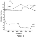
На фиг.1 показан график изменения температуры по времени для стандартного регулирования температуры;Figure 1 shows a graph of temperature over time for standard temperature control;
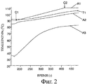
на фиг.2 показан график изменения температуры по времени для постепенного регулирования путем увеличения заданного значения в соответствии с настоящим изобретением;figure 2 shows a graph of temperature over time for gradual regulation by increasing the set value in accordance with the present invention;
на фиг.3 показан график изменения температуры по времени для постепенного регулирования путем уменьшения заданного значения в соответствии с настоящим изобретением;figure 3 shows a graph of temperature over time for gradual regulation by reducing the set value in accordance with the present invention;
на фиг.4 схематично показано устройство в соответствии с настоящим изобретением;figure 4 schematically shows a device in accordance with the present invention;
на фиг.5 показана схема осуществления способа в соответствии с настоящим изобретением.figure 5 shows a diagram of the implementation of the method in accordance with the present invention.
На фиг.1 показан график традиционного регулирования температуры двигателя. В данном случае устройство, обеспечивающее открытие клапанного устройства, содержит известный классический термостат, расширяющаяся жидкость которого обеспечивает открытие клапана при данной температуре. На графике, показанном на фиг.1, кривая А1 показывает заданную температуру, а кривая T1 - температуру охлаждающей жидкости, то есть температуру двигателя. В представленном примере заданное значение резко переходит от 90°С к 110°С, образуя ступень или уступ A11. Следует отметить, что температура охлаждающей жидкости не сразу достигает этого заданного значения, а претерпевает несколько колебаний, прежде чем достичь температуры регулирования термостата. Эти колебания объясняются резким перепадом температуры на входе в радиатор (кривая А2) и на выходе из радиатора (кривая A3). Поток охлаждающей жидкости начинается так же резко, как и изменение заданного значения, что приводит к существенному усталостному износу системы охлаждения.Figure 1 shows a graph of a conventional engine temperature control. In this case, the device for opening the valve device contains a well-known classic thermostat, the expanding liquid of which ensures the opening of the valve at a given temperature. In the graph shown in FIG. 1, curve A1 shows the set temperature, and curve T1 shows the temperature of the coolant, that is, the temperature of the engine. In the presented example, the setpoint sharply changes from 90 ° C to 110 ° C, forming a step or step A11. It should be noted that the temperature of the coolant does not immediately reach this preset value, but undergoes several fluctuations before reaching the control temperature of the thermostat. These fluctuations are explained by a sharp temperature drop at the radiator inlet (curve A2) and at the radiator outlet (curve A3). The flow of coolant starts as abruptly as a change in the setpoint, which leads to significant fatigue wear of the cooling system.
Эти резкие изменения температуры на данном режиме работы приводят к возникновению напряжений, отрицательно действующих на радиатор и ускоряющих его износ.These sudden changes in temperature in this mode of operation lead to stresses that adversely affect the radiator and accelerate its wear.
На фиг.2 и 3 показано регулирование температуры двигателя, осуществляемое посредством способа и устройства в соответствии с настоящим изобретением.Figure 2 and 3 shows the temperature control of the engine, carried out by the method and device in accordance with the present invention.
На фиг.2 показано изменение заданного значения (кривая А1) температуры от низкой С1 90°С до высокой С2 110°С. Температура двигателя (кривая Т1) повышается так же, как и заданное значение (более медленно), и без какого-либо колебания. Для температуры на входе радиатора (кривая А2) наблюдается такой же наклонный профиль температур, поэтому напряжения на радиатор ослабляются. В этом случае заданную температуру получают постепенным закрытием клапанного устройства при постепенном уменьшении нагрева сопротивления. Это объясняет тот факт, что температура на входе в радиатор продолжает повышаться. Действительно, постепенное закрытие клапанного устройства приводит к нагреву охлаждающей жидкости, и небольшое количество жидкости, которое продолжает поступать в радиатор, становится все горячее, таким образом возникает повышение температуры, наблюдаемое на кривой А2.Figure 2 shows the change in the set value (curve A1) of the temperature from
На фиг.3 показан график изменения заданного значения температуры (кривая А1) от высокой С2 к низкой С1. Сопротивление греется все сильнее и сильнее. Температура охлаждения двигателя и температура на входе в радиатор следуют этому наклону, но более хаотично, и наблюдается наличие незначительных температурных ступеней, возникающих за счет изменения работы двигателя (изменение режима и нагрузки двигателя).Figure 3 shows a graph of the change in the setpoint temperature (curve A1) from high C2 to low C1. Resistance is getting stronger and stronger. The cooling temperature of the engine and the temperature at the inlet to the radiator follow this slope, but more chaotically, and there are minor temperature steps that occur due to changes in engine operation (change in engine mode and load).
На фиг.4 показан вариант выполнения устройства в соответствии с настоящим изобретением, позволяющий получить результаты, показанные на фиг.2 и 3. Двигатель 1 внутреннего сгорания и радиатор 2 соединены между собой участками 11, 11' замкнутого контура, по которому циркулирует охлаждающая жидкость 10. Этот контур позволяет охлаждающей жидкости протекать от двигателя 1 к радиатору 2, а затем от радиатора к двигателю по другому участку 11'. Участок 11 контура выполнен с перепускным трубопроводом 12, позволяющим охлаждающей жидкости возвращаться в двигатель 1 напрямую, минуя радиатор 2. На пути первого участка 11 контура между двигателем 1 и радиатором 2 и после перепускного трубопровода 12 установлено клапанное устройство 3 типа термостата. Это клапанное устройство 3, изображенное в виде квадрата, содержит канал (не показан) для прохода охлаждающей жидкости от двигателя 1 к радиатору 2, перекрываемый клапаном, и термостатический элемент управления этим клапаном. Этот термостатический элемент управления обеспечивает циркуляцию охлаждающей жидкости от двигателя 1 в направлении радиатора 2 только в том случае, когда температура в последнем достигает определенного значения.Figure 4 shows an embodiment of the device in accordance with the present invention, which allows to obtain the results shown in figures 2 and 3. The
Термостатический элемент управления является элементом описанного выше типа. Принцип его работы основан на расширении объема воска, содержащегося в капсуле. Под действием температуры охлаждающей жидкости восковая капсула за счет теплового расширения, откалиброванного по температуре, управляет открытием клапана 32 через рабочий поршень. Таким образом, клапан 32 открывается или закрывается, регулируя расход охлаждающей жидкости и, в случае необходимости, перепуская жидкость через перепускной трубопровод 12. В соответствии с настоящим изобретением термостат - клапанное устройство 3 - открывается, когда температура охлаждающей жидкости достигает стандартной заданной температуры 110°С. Этот термостат содержит нагревательное средство в виде терморезистора 31, позволяющее искусственно повышать температуру воска и менять таким образом его заданную температуру. Иначе говоря, термостат (клапанное устройство 3), который обычно приводит в действие клапан 32, когда охлаждающая жидкость нагревается до 110°С, теперь срабатывает, когда охлаждающая жидкость достигает температуры 90°С, благодаря терморезистору 31, которое искусственно доводит термостат до 110°С. Этот терморезистор 31 предназначен для опережающего открытия клапанного устройства 3. Терморезистор 31 соединен с вычислительным устройством 4 транспортного средства, которое подает команды, необходимые для осуществления процесса.The thermostatic control is an element of the type described above. The principle of its operation is based on the expansion of the volume of wax contained in the capsule. Under the influence of the temperature of the coolant, the wax capsule, due to thermal expansion calibrated by temperature, controls the opening of valve 32 through the working piston. Thus, the valve 32 opens or closes, regulating the flow rate of the coolant and, if necessary, bypassing the fluid through the bypass line 12. In accordance with the present invention, the thermostat - valve device 3 - opens when the temperature of the coolant reaches a standard set temperature of 110 ° C. . This thermostat contains heating means in the form of a thermistor 31, which allows you to artificially increase the temperature of the wax and thus change its set temperature. In other words, the thermostat (valve device 3), which usually actuates the valve 32 when the coolant is heated to 110 ° C, now works when the coolant reaches a temperature of 90 ° C, thanks to the thermistor 31, which artificially brings the thermostat to 110 ° FROM. This thermistor 31 is designed to advance the opening of the valve device 3. The thermistor 31 is connected to the computing device 4 of the vehicle, which gives the commands necessary for the process.
Контур охлаждения содержит также по меньшей мере один датчик 101 температуры, установленный в участке 11 контура на выходе из двигателя 1 и на входе в клапанное устройство 3. Второй датчик 102 можно установить в участке 11 контура охлаждения между выходом из клапанного устройства 3 и входом в радиатор 2. Эти два датчика температуры тоже соединены с вычислительным устройством 4. Первый датчик 101 позволяет измерять температуру Т1 охлаждающей жидкости на выходе из двигателя. Результат измерения направляется в вычислительное устройство 4, которое сохраняет его в запоминающих средствах, находящихся в запоминающем модуле 47. Второй датчик 102 позволяет измерять температуру охлаждающей жидкости на входе в радиатор 2. Из соображений экономии классические автотранспортные средства не оборудуют вторым датчиком 102, используемым только во время испытаний двигателя. Все измерения, необходимые для регулирования температуры двигателя во время эксплуатации автомобиля, производятся первым датчиком 101 температуры.The cooling circuit also contains at least one temperature sensor 101 installed in the circuit section 11 at the outlet of the
Устройство содержит также модуль 45 контроля для определения, произошло ли первое открытие клапанного устройства, поскольку он используется только после этого первого открытия. Действительно, во время первого открытия клапанного устройства разность между температурой двигателя и заданной температурой слишком велика для использования постепенной заданной величины.The device also includes a control module 45 for determining whether the valve is first opened, since it is only used after this first opening. Indeed, during the first opening of the valve device, the difference between the engine temperature and the set temperature is too large to use a gradual set value.
Во время запуска двигателя происходит первое открытие, которое можно осуществлять с использованием средств, позволяющих избежать слишком большого теплового удара. Для этого первое открытие клапанного устройства, стандартное заданное значение для которого равно 110°С, происходит с опережением. Это значит, что устройство содержит средства, открывающие клапанное устройство при температуре охлаждающей жидкости, равной 90°С, а не 110°С. Такой эффект получают за счет использования терморезистора 31 термостата. Во время открытия модуль 45 контроля принимает значение ТС, указывающее на то, что первое открытие состоялось. Именно этот модуль 45 контроля используют в качестве средства контроля первого открытия в устройстве регулирования в соответствии с настоящим изобретением.During engine start-up, the first opening occurs, which can be accomplished using means to avoid too much heat stroke. For this, the first opening of the valve device, the standard setpoint for which is 110 ° C, is ahead of schedule. This means that the device contains means that open the valve device at a coolant temperature of 90 ° C, and not 110 ° C. This effect is obtained through the use of a thermostat 31. During the opening, the monitoring unit 45 takes on a TC value indicating that the first opening has taken place. It is this control module 45 that is used as a means of controlling a first opening in a control device in accordance with the present invention.
Первый датчик 101 используется для измерения температуры Т1 охлаждающей жидкости на выходе из двигателя во время непрерывного режима работы при движении транспортного средства, а также для контроля температуры двигателя и проверки достижения заданной температуры.The first sensor 101 is used to measure the temperature T1 of the coolant at the exit of the engine during continuous operation when the vehicle is in motion, as well as to monitor the temperature of the engine and verify that the set temperature has been reached.
Для этого устройство содержит по меньшей мере один первый вычислительный модуль 41, откалиброванный на транспортном средстве или на стенде, позволяющий определять минимальную В1 и максимальную В2 предельные температуры в зависимости от минимальной С1 и максимальной С2 заданных температур, значения которых хранятся в запоминающих средствах 47, находящихся в вычислительном устройстве 4. Эти минимальная В1 и максимальная В2 предельные температуры находятся в интервале между минимальной С1 и максимальной С2 заданными температурами, т.е. первый вычислительный модуль 41 определяет значение минимальной предельной температуры В1, превышающее минимальную заданную температуру С1, и значение максимальной предельной температуры В2, меньшей максимальной заданной температуры С2. Например, если минимальная заданная температура С1 равна 90°С, а максимальная заданная температура С2 равна 110°С, то минимальная предельная температура В1 может быть равной 92°С, а максимальная предельная температура (В2) может быть равной 108°С. Эта разность температур обеспечивает запас надежности.For this, the device contains at least one first computing module 41, calibrated on the vehicle or on the stand, which allows to determine the minimum B1 and maximum B2 maximum temperature depending on the minimum C1 and maximum C2 set temperatures, the values of which are stored in storage means 47 located in computing device 4. These minimum B1 and maximum B2 limit temperatures are between the minimum C1 and maximum C2 set temperatures, i.e. the first computing module 41 determines the value of the minimum limit temperature B1 in excess of the minimum set temperature C1, and the value of the maximum limit temperature B2 less than the maximum set temperature C2. For example, if the minimum setpoint temperature C1 is 90 ° C and the maximum setpoint temperature C2 is 110 ° C, then the minimum limit temperature B1 can be equal to 92 ° C and the maximum limit temperature (B2) can be equal to 108 ° C. This temperature difference provides a margin of safety.
Устройство содержит второй вычислительный модуль 42, откалиброванный на транспортном средстве или на стенде, который позволяет определить заданный температурный профиль. Для этого указанный модуль вычисляет несколько промежуточных температур I1 между минимальной предельной температурой В1 и максимальной предельной температурой В2. Эти промежуточные температуры I1 предназначены для постепенного достижения минимальной С1 или максимальной С2 заданной температуры.The device contains a second computing module 42, calibrated on the vehicle or on the stand, which allows you to determine a given temperature profile. To do this, the specified module calculates several intermediate temperatures I1 between the minimum limit temperature B1 and the maximum limit temperature B2. These intermediate temperatures I1 are intended to gradually reach the minimum C1 or maximum C2 set temperature.
Как вариант, профиль заранее может быть введен в память вычислительного устройства 4.Alternatively, the profile can be pre-stored in the memory of computing device 4.
Устройство содержит также модуль 43 сравнения, позволяющий сравнивать температуру Т1, измеряемую непрерывно на выходе двигателя датчиком 101 температуры во время движения транспортного средства, с промежуточными температурами I1, вычисленными вторым вычислительным модулем 42. Это сравнение позволяет определить отклонение Е между этими двумя температурами. Это отклонение Е передается на модуль 44 коррекции отклонения, позволяющий определить величину, на которую необходимо открыть клапанное устройство для достижения требуемой заданной температуры в зависимости от измеренного отклонения Е.The device also includes a comparison module 43, which allows you to compare the temperature T1, measured continuously at the engine output by the temperature sensor 101 while the vehicle is moving, with the intermediate temperatures I1 calculated by the second computing module 42. This comparison allows you to determine the deviation E between these two temperatures. This deviation E is transmitted to the deviation correction module 44, which makes it possible to determine the amount by which the valve device must be opened to achieve the desired set temperature, depending on the measured deviation E.
Этот модуль 44 коррекции связан с модулем 46 управления термостатом для подачи команды на включение термосопротивления.This correction module 44 is connected to the thermostat control module 46 to issue a command to turn on the thermal resistance.
В варианте выполнения устройства вычислительный модуль и модуль коррекции могут быть объединены в регулятор типа PID (пропорциональная, интегральная, дифференциальная функции). Этот регулятор действует на значение регулирования, в данном случае значением регулирования является температура, например, для управления терморезистором, клапаном, вентилем и т.д.In an embodiment of the device, the computational module and the correction module can be combined into a controller of the PID type (proportional, integral, differential functions). This controller acts on the control value, in this case the control value is temperature, for example, to control a thermistor, valve, valve, etc.
Указанный тип регулятора объединяет три действия:The specified type of controller combines three actions:
- пропорциональное действие (Р): выходное значение регулятора прямо пропорционально отклонению между измеренным значением и заданным значением. При таком типе регулирования измеренное значение никогда не достигает заданного значения: назначение регулятора состоит в минимизации этого отклонения;- proportional action (P): the output value of the controller is directly proportional to the deviation between the measured value and the set value. With this type of regulation, the measured value never reaches the set value: the purpose of the regulator is to minimize this deviation;
- интегральное действие (I): интегральное действие позволяет устранить отклонение между измерением и заданным значением и, следовательно, повысить точность регулирования. Оно позволяет производить интегрирование (в математическом смысле термина) отклонения. Это интегральное действие практически всегда связано с пропорциональным действием;- integral action (I): the integral action eliminates the deviation between the measurement and the set value and, therefore, improves the accuracy of regulation. It allows the integration (in the mathematical sense of the term) of the deviation. This integral action is almost always associated with a proportional action;
- дифференциальное действие (D): состоит в дифференцировании (в математическом смысле термина) отклонения между измерением и заданным значением. Дифференциальное действие позволяет сократить время реагирования регулирования и стабилизировать регулирование (когда колебания контролируемых значений являются слишком резкими). Дифференциальное действие дополняет пропорциональное действие.- differential action (D): consists in differentiating (in the mathematical sense of the term) the deviation between the measurement and the given value. Differential action reduces the response time of the regulation and stabilizes the regulation (when the fluctuations of the monitored values are too sharp). Differential action complements proportional action.
Далее следует подробное описание работы этого устройства со ссылкой на фиг.5.The following is a detailed description of the operation of this device with reference to figure 5.
Перед началом регулирования двигателя определяют минимальную и максимальную температуры и сохраняют их (201, 202) в запоминающем модуле 47 вычислительного устройства 4.Before starting the regulation of the engine, the minimum and maximum temperatures are determined and stored (201, 202) in the storage module 47 of the computing device 4.
Во время движения температура Т1 охлаждающей жидкости на выходе двигателя непрерывно измеряется (200) температурным датчиком 101. Измеренное значение температуры Т1 направляется в вычислительное устройство 4.During movement, the temperature T1 of the coolant at the engine outlet is continuously measured (200) by the temperature sensor 101. The measured temperature T1 is sent to the computing device 4.
Если модуль 45 контроля получает значение температуры ТС, указывающее, что произошло первое открытие, включается регулирование двигателя в соответствии с настоящим изобретением.If the monitoring unit 45 receives a temperature value of the vehicle indicating that the first opening has occurred, the engine control in accordance with the present invention is turned on.
При помощи первого вычислительного модуля 41 вычислительное устройство 4 использует минимальную С1 и максимальную С2 заданные температуры для определения (210) минимальной В1 и максимальной В2 предельных температур. Как правило, минимальная С1 и максимальная С2 заданные температуры равны 90°С и 110°С соответственно, а минимальная В1 и максимальная В2 предельные температуры, определенные первым вычислительным модулем, могут равняться 92°С и 102°С соответственно.Using the first computing module 41, computing device 4 uses the minimum C1 and maximum C2 set temperatures to determine (210) the minimum B1 and maximum B2 limit temperatures. As a rule, the minimum C1 and maximum C2 set temperatures are 90 ° C and 110 ° C, respectively, and the minimum B1 and maximum B2 limit temperatures determined by the first computing module can be 92 ° C and 102 ° C, respectively.
Эти значения предельных температур С1, С2 сохраняются (211, 212) в запоминающем модуле 47 вычислительного устройства 4.These values of the limiting temperatures C1, C2 are stored (211, 212) in the storage module 47 of the computing device 4.
После этого второй модуль 42 вычислительного устройства 4 вычисляет промежуточные заданные температуры I1 температурного профиля, определенного, начиная с минимальной В1 и максимальной В2 предельных температур, для постепенного достижения заданной температуры С1, С2.After that, the second module 42 of the computing device 4 calculates the intermediate set temperatures I1 of the temperature profile, determined starting from the minimum B1 and maximum B2 of the limiting temperatures, to gradually reach the set temperature C1, C2.
Непрерывно измеряемую (200) на выходе двигателя температуру Т1 сравнивают с различными промежуточными температурами I1 для определения отклонения Е при помощи модуля 43 сравнения. Значения отклонений Е регулярно направляются в модуль 44 коррекции отклонения, который позволяет определить (240) степень открытия или закрытия (250) клапанного устройства, необходимую для коррекции отклонения Е и достижения таким образом требуемого заданного значения, следуя заданному профилю.The continuously measured (200) at the engine outlet temperature T1 is compared with various intermediate temperatures I1 to determine the deviation E using the comparison module 43. The deviation values E are regularly sent to the deviation correction module 44, which allows you to determine (240) the degree of opening or closing (250) of the valve device necessary to correct the deviation E and thus achieve the desired set value, following the set profile.
Коррекцию осуществляют посредством модуля 46 управления, подающего сигнал на изменение температуры термосопротивления 31. Когда термосопротивление 31 нагревается, клапанное устройство постепенно открывается, а когда термосопротивление 31 охлаждается, клапанное устройство постепенно закрывается.The correction is carried out by the control module 46, which signals the change in temperature of the thermoresistance 31. When the thermistor 31 is heated, the valve device is gradually opened, and when the thermistor 31 is cooled, the valve device is gradually closed.
Таким образом, работа устройства в соответствии с настоящим изобретением содержит следующие этапы:Thus, the operation of the device in accordance with the present invention comprises the following steps:
- определение значения минимальной заданной температуры С1 и максимальной заданной температуры С2 и сохранение (201, 202) этих двух заданных температур в запоминающих средствах 47 вычислительного устройства 4;- determination of the minimum set temperature C1 and the maximum set temperature C2 and storing (201, 202) of these two set temperatures in the storage means 47 of the computing device 4;
- определение (210) первым вычислительным модулем 41 значения минимальной предельной температуры В1, начиная с минимальной заданной температуры С1, и значения максимальной предельной температуры В2, начиная с максимальной заданной температуры С2, и сохранение (211, 212) этих двух заданных температур в запоминающих средствах 47 вычислительного устройства 4;- determining (210) by the first computing module 41 the values of the minimum limit temperature B1, starting from the minimum set temperature C1, and the values of the maximum limit temperature B2, starting from the maximum set temperature C2, and storing (211, 212) of these two set temperatures in the storage means 47 computing device 4;
- определение (220) вторым вычислительным модулем 42 промежуточных температур I1 в зависимости от минимальной В1 и максимальной В2 предельных температур;- determination (220) by the second computing module 42 of intermediate temperatures I1 depending on the minimum B1 and maximum B2 maximum temperature;
- непрерывное измерение (200) в течение всего времени движения температуры Т1 находящейся в контуре охлаждающей жидкости на выходе из двигателя 1 и на выходе из клапанного устройства 3 при помощи датчика 101;- continuous measurement (200) during the whole time the temperature T1 moves in the coolant circuit at the outlet of the
- сравнение (230) температуры на выходе из двигателя с различными промежуточными температурами I1 для определения отклонения Е;- comparison (230) of the temperature at the outlet of the engine with various intermediate temperatures I1 to determine the deviation E;
- коррекция (240) температурного отклонения Е путем открытия или закрытия (250) клапанного устройства.- correction (240) of the temperature deviation E by opening or closing (250) the valve device.
В представленном примере клапанное устройство 3 является устройством типа термостата, однако можно использовать и другое клапанное устройство перепуска охлаждающей жидкости, например электрически управляемый клапан, и, следовательно, производить регулирование по другим дополнительным критериям, кроме температуры.In the presented example, the valve device 3 is a thermostat type device, however, it is possible to use another valve device for bypassing the coolant, for example, an electrically controlled valve, and, therefore, to perform regulation according to other additional criteria, in addition to temperature.
В рамках изобретения был описан пример защиты радиатора. Однако в качестве примера можно взять любой другой теплообменник или даже компоненты, не относящиеся к тепловому двигателю, которые не должны подвергаться тепловому удару выше определенного уровня.An example of radiator protection has been described within the scope of the invention. However, as an example, you can take any other heat exchanger or even components that are not related to the heat engine, which should not be subjected to thermal shock above a certain level.
Также данный способ защиты можно применить для других типов двигателей, содержащих вспомогательные компоненты, которым необходима тепловая защита, например электрические приводы или гибридные системы.Also, this protection method can be applied to other types of engines containing auxiliary components that require thermal protection, such as electric drives or hybrid systems.
В представленном примере высокая температура и низкая температура были выбраны путем различных приближений. В зависимости от изменения условий можно выбирать другие значения (более низкие или более высокие).In the presented example, high temperature and low temperature were selected by various approximations. Other values (lower or higher) can be selected depending on the changing conditions.
Специалисту очевидно, что настоящее изобретение может быть осуществлено в различных вариантах выполнения и других специфических версиях, не удаляясь при этом от указанной области применения. Различные варианты выполнения следует рассматривать в качестве иллюстрации, но их можно изменять в объеме прилагаемой формулы изобретения, а изобретение не следует ограничивать представленными выше деталями.It will be apparent to those skilled in the art that the present invention may be practiced in various embodiments and other specific versions without departing from the specified field of application. Various embodiments should be considered as illustrations, but they can be changed within the scope of the attached claims, and the invention should not be limited to the above details.
Claims (10)
определяют минимальную (С1) и максимальную (С2) заданные температуры и сохраняют (201, 202) эти два значения в запоминающих средствах (47) вычислительного устройства (4),
определяют посредством первого вычислительного модуля (41) минимальную предельную температуру (В1) на основании минимальной заданной температуры (С1) и максимальную предельную температуру (В2) на основании максимальной заданной температуры (С2) и сохраняют эти два значения заданных температур в запоминающих средствах (47) вычислительного устройства (4);
определяют (220) посредством второго вычислительного модуля (42) промежуточные температуры (I1) в зависимости от минимальной (В1) и максимальной (В2) предельных температур;
непрерывно измеряют (200) при помощи датчика (101) в течение всего времени движения температуру (Т1) находящейся в контуре охлаждающей жидкости между выходом двигателя (1) и входом клапанного устройства (3);
сравнивают (230) температуру на выходе двигателя с различными промежуточными температурами (II) для определения отклонения (Е);
корректируют (240) температурное отклонение (Е) посредством открытия или закрытия (250) клапанного устройства.6. The method of controlling the temperature of the engine according to claim 5, characterized in that:
determine the minimum (C1) and maximum (C2) set temperatures and store (201, 202) these two values in the storage means (47) of the computing device (4),
determine by means of the first computing module (41) the minimum limit temperature (B1) based on the minimum set temperature (C1) and the maximum limit temperature (B2) based on the maximum set temperature (C2) and store these two values of the set temperatures in the storage means (47) computing device (4);
determining (220) by means of a second computing module (42) intermediate temperatures (I1) depending on the minimum (B1) and maximum (B2) limit temperatures;
continuously measure (200) with a sensor (101) during the entire time of movement the temperature (T1) in the coolant circuit between the engine outlet (1) and the valve device inlet (3);
compare (230) the temperature at the engine outlet with various intermediate temperatures (II) to determine the deviation (E);
adjust (240) the temperature deviation (E) by opening or closing (250) the valve device.
Applications Claiming Priority (2)
| Application Number | Priority Date | Filing Date | Title |
|---|---|---|---|
| FR0600485A FR2896271B1 (en) | 2006-01-19 | 2006-01-19 | METHOD AND DEVICE FOR CONTROLLING THE TEMPERATURE OF AN INTERNAL COMBUSTION ENGINE |
| FR0600485 | 2006-01-19 |
Publications (2)
| Publication Number | Publication Date |
|---|---|
| RU2008134003A RU2008134003A (en) | 2010-02-27 |
| RU2411373C2 true RU2411373C2 (en) | 2011-02-10 |
Family
ID=36704033
Family Applications (1)
| Application Number | Title | Priority Date | Filing Date |
|---|---|---|---|
| RU2008134003/06A RU2411373C2 (en) | 2006-01-19 | 2007-01-18 | Temperature regulating method and device of internal combustion engine |
Country Status (8)
| Country | Link |
|---|---|
| US (1) | US20090126656A1 (en) |
| EP (1) | EP1974134B1 (en) |
| JP (1) | JP2009523948A (en) |
| CN (1) | CN101384805B (en) |
| AT (1) | ATE541114T1 (en) |
| FR (1) | FR2896271B1 (en) |
| RU (1) | RU2411373C2 (en) |
| WO (1) | WO2007083065A2 (en) |
Cited By (2)
| Publication number | Priority date | Publication date | Assignee | Title |
|---|---|---|---|---|
| RU2578253C1 (en) * | 2012-05-04 | 2016-03-27 | Сканиа Св Аб | Cooling system and vehicle containing this cooling system |
| RU2715463C2 (en) * | 2016-11-01 | 2020-02-28 | Форд Глобал Текнолоджиз, Ллк | Control method of vehicle cooling system (embodiments) and system for vehicle |
Families Citing this family (10)
| Publication number | Priority date | Publication date | Assignee | Title |
|---|---|---|---|---|
| FR2847639B1 (en) * | 2002-11-21 | 2005-02-04 | Renault Sa | METHOD FOR CONTROLLING AUTOMATIC TRANSMISSION OF A VEHICLE IN A DOWNLOAD SITUATION |
| US9096215B2 (en) * | 2010-12-17 | 2015-08-04 | Volvo Lastvagnar Ab | Method to control a drivetrain of a vehicle |
| JP5641037B2 (en) * | 2012-11-20 | 2014-12-17 | トヨタ自動車株式会社 | Cooling system |
| DE102013003144B4 (en) * | 2013-02-25 | 2017-06-08 | Audi Ag | Method for operating a cooling system of a motor vehicle and motor vehicle |
| SE539027C2 (en) | 2013-04-25 | 2017-03-21 | Scania Cv Ab | Procedure and system for controlling a cooling system |
| JP6691355B2 (en) * | 2015-06-11 | 2020-04-28 | 株式会社ミクニ | Flow controller |
| CN106089395B (en) * | 2016-07-26 | 2018-11-02 | 广州汽车集团股份有限公司 | Engine water temperature control method and device |
| CN113204860B (en) * | 2021-03-17 | 2024-05-31 | 联合汽车电子有限公司 | Calibration method |
| CN114542263B (en) * | 2022-03-22 | 2023-04-18 | 潍柴动力股份有限公司 | Cooling water temperature regulation and control method and control system |
| CN117193415B (en) * | 2023-09-13 | 2025-12-30 | 北京航空航天大学 | A rapid temperature change tracking control system and its control method under air-cooled-hot environment |
Citations (5)
| Publication number | Priority date | Publication date | Assignee | Title |
|---|---|---|---|---|
| FR2456838A1 (en) * | 1979-05-18 | 1980-12-12 | Sev Marchal | Thermostat valve in IC engine cooling circuit - responds to temperature of cooling medium to control flow through radiator and by=pass line |
| SU1763687A1 (en) * | 1990-12-06 | 1992-09-23 | В, Н. Тимофеев, Е. А. Киселев, В. Д. Мирошниченко, Е. В. Кротов и Г. Е. Андреев | Device for temperature control of internal combustion engine coolant |
| US5494005A (en) * | 1993-09-07 | 1996-02-27 | Behr-Thomson-Dehnstoffregler Gmbh & Co. | Cooling system for an internal combustion engine of a motor vehicle comprising a valve |
| US5529025A (en) * | 1993-07-19 | 1996-06-25 | Bayerische Motoren Werke Ag | Cooling system for an internal-combustion engine of a motor vehicle comprising a thermostatic valve which contains an electrically heatable expansion element |
| RU2204030C1 (en) * | 2001-09-03 | 2003-05-10 | Открытое акционерное общество "Чебоксарское научно-производственное приборостроительное предприятие "ЭЛАРА" | Internal combustion engine cooling liquid temperature regulator |
Family Cites Families (15)
| Publication number | Priority date | Publication date | Assignee | Title |
|---|---|---|---|---|
| DE3316060C1 (en) * | 1983-05-03 | 1984-09-20 | Süddeutsche Kühlerfabrik Julius Fr. Behr GmbH & Co KG, 7000 Stuttgart | Electrical circuit arrangement for regulating the cooling and heating power for the interior of motor vehicles |
| DE19519378B4 (en) * | 1995-05-26 | 2011-06-30 | Bayerische Motoren Werke Aktiengesellschaft, 80809 | Cooling system with electrically adjustable actuator |
| FR2804719B1 (en) * | 2000-02-03 | 2002-06-21 | Peugeot Citroen Automobiles Sa | COOLING DEVICE OF A MOTOR VEHICLE ENGINE |
| FR2806444B1 (en) * | 2000-03-17 | 2002-06-07 | Peugeot Citroen Automobiles Sa | COOLING DEVICE OF A MOTOR VEHICLE ENGINE |
| US6453993B1 (en) * | 2000-05-17 | 2002-09-24 | Carrier Corporation | Advanced starting control for multiple zone system |
| CA2325168A1 (en) * | 2000-11-06 | 2002-05-06 | Joseph Fishman | Electronically controlled thermostat |
| DE10123444B4 (en) * | 2001-05-14 | 2006-11-09 | Siemens Ag | Control system for controlling the coolant temperature of an internal combustion engine |
| EP1273901A1 (en) * | 2001-07-02 | 2003-01-08 | Université de Liège | Method and apparatus for automatic measurement of particle size and form |
| JP3809349B2 (en) * | 2001-07-25 | 2006-08-16 | トヨタ自動車株式会社 | Cooling device for internal combustion engine |
| JP3912104B2 (en) * | 2001-12-25 | 2007-05-09 | 三菱自動車工業株式会社 | Engine cooling system |
| JP4027684B2 (en) * | 2002-03-08 | 2007-12-26 | トヨタ自動車株式会社 | Engine cooling system |
| JP3957531B2 (en) * | 2002-03-08 | 2007-08-15 | トヨタ自動車株式会社 | Engine cooling system |
| DE10318355A1 (en) * | 2003-04-23 | 2004-12-02 | Adam Opel Ag | Cooling system for a combustion engine has control circuit to change heating power if rate of change of deviation from ideal temperature exceeds a threshold value |
| DE10337412A1 (en) * | 2003-08-14 | 2005-03-10 | Daimler Chrysler Ag | Method for controlling a thermostat |
| KR100589140B1 (en) * | 2003-09-20 | 2006-06-12 | 현대자동차주식회사 | Vehicle Cooling System Control Method |
-
2006
- 2006-01-19 FR FR0600485A patent/FR2896271B1/en not_active Expired - Fee Related
-
2007
- 2007-01-18 CN CN200780005961XA patent/CN101384805B/en not_active Expired - Fee Related
- 2007-01-18 US US12/161,440 patent/US20090126656A1/en not_active Abandoned
- 2007-01-18 JP JP2008550821A patent/JP2009523948A/en active Pending
- 2007-01-18 AT AT07718163T patent/ATE541114T1/en active
- 2007-01-18 WO PCT/FR2007/050663 patent/WO2007083065A2/en not_active Ceased
- 2007-01-18 RU RU2008134003/06A patent/RU2411373C2/en not_active IP Right Cessation
- 2007-01-18 EP EP07718163A patent/EP1974134B1/en active Active
Patent Citations (5)
| Publication number | Priority date | Publication date | Assignee | Title |
|---|---|---|---|---|
| FR2456838A1 (en) * | 1979-05-18 | 1980-12-12 | Sev Marchal | Thermostat valve in IC engine cooling circuit - responds to temperature of cooling medium to control flow through radiator and by=pass line |
| SU1763687A1 (en) * | 1990-12-06 | 1992-09-23 | В, Н. Тимофеев, Е. А. Киселев, В. Д. Мирошниченко, Е. В. Кротов и Г. Е. Андреев | Device for temperature control of internal combustion engine coolant |
| US5529025A (en) * | 1993-07-19 | 1996-06-25 | Bayerische Motoren Werke Ag | Cooling system for an internal-combustion engine of a motor vehicle comprising a thermostatic valve which contains an electrically heatable expansion element |
| US5494005A (en) * | 1993-09-07 | 1996-02-27 | Behr-Thomson-Dehnstoffregler Gmbh & Co. | Cooling system for an internal combustion engine of a motor vehicle comprising a valve |
| RU2204030C1 (en) * | 2001-09-03 | 2003-05-10 | Открытое акционерное общество "Чебоксарское научно-производственное приборостроительное предприятие "ЭЛАРА" | Internal combustion engine cooling liquid temperature regulator |
Cited By (2)
| Publication number | Priority date | Publication date | Assignee | Title |
|---|---|---|---|---|
| RU2578253C1 (en) * | 2012-05-04 | 2016-03-27 | Сканиа Св Аб | Cooling system and vehicle containing this cooling system |
| RU2715463C2 (en) * | 2016-11-01 | 2020-02-28 | Форд Глобал Текнолоджиз, Ллк | Control method of vehicle cooling system (embodiments) and system for vehicle |
Also Published As
| Publication number | Publication date |
|---|---|
| EP1974134B1 (en) | 2012-01-11 |
| WO2007083065A3 (en) | 2007-09-07 |
| CN101384805A (en) | 2009-03-11 |
| FR2896271B1 (en) | 2012-08-17 |
| WO2007083065A2 (en) | 2007-07-26 |
| RU2008134003A (en) | 2010-02-27 |
| JP2009523948A (en) | 2009-06-25 |
| ATE541114T1 (en) | 2012-01-15 |
| CN101384805B (en) | 2010-09-15 |
| EP1974134A2 (en) | 2008-10-01 |
| US20090126656A1 (en) | 2009-05-21 |
| FR2896271A1 (en) | 2007-07-20 |
Similar Documents
| Publication | Publication Date | Title |
|---|---|---|
| RU2411373C2 (en) | Temperature regulating method and device of internal combustion engine | |
| RU2411372C2 (en) | Procedure and device for control of thermostat first opening regulating temperature of internal combustion engine | |
| RU2620928C2 (en) | Engine cooling system method (versions) and vehicle system | |
| RU2620467C2 (en) | Engine cooling system diagnostics (versions) and vehicle system | |
| RU2637274C2 (en) | Method, method for vehicle and vehicle system | |
| RU2602845C2 (en) | Method of diagnostics of vehicle cooling system (versions) and vehicle | |
| US9581075B2 (en) | Coolant control systems and methods for warming engine oil and transmission fluid | |
| US7263954B2 (en) | Internal combustion engine coolant flow | |
| JP4962657B2 (en) | Control device for internal combustion engine | |
| RU2536469C1 (en) | Cooling system for internal combustion engine cooling | |
| KR102496812B1 (en) | Control method of cooling system | |
| JP2001041040A (en) | Control device for cooling water flow rate and lubricating oil flow rate in heat exchanger | |
| US10731542B2 (en) | Internal combustion engine cooling system | |
| CN116753062A (en) | An engine cooling system and control method based on thermal management module | |
| US20200088086A1 (en) | Engine cooling system | |
| CN114738103B (en) | A control method and device for a vehicle temperature control module | |
| Wilson et al. | A Comparative Study on Engine Thermal Management System | |
| EP1411215A1 (en) | Engine oil cooling | |
| US10612452B2 (en) | Control method of coolant control valve unit | |
| JP7626029B2 (en) | Control device | |
| KR102552021B1 (en) | Control method of cooling system | |
| KR20230070728A (en) | Control method of engine coolant valve | |
| JP2019190499A (en) | Oil temperature control device | |
| KR19980051582A (en) | Car's chiller |
Legal Events
| Date | Code | Title | Description |
|---|---|---|---|
| MM4A | The patent is invalid due to non-payment of fees |
Effective date: 20130119 |