RU2407224C2 - Depth perception - Google Patents
Depth perception Download PDFInfo
- Publication number
- RU2407224C2 RU2407224C2 RU2007142457/09A RU2007142457A RU2407224C2 RU 2407224 C2 RU2407224 C2 RU 2407224C2 RU 2007142457/09 A RU2007142457/09 A RU 2007142457/09A RU 2007142457 A RU2007142457 A RU 2007142457A RU 2407224 C2 RU2407224 C2 RU 2407224C2
- Authority
- RU
- Russia
- Prior art keywords
- pixels
- input
- group
- output
- overlay
- Prior art date
Links
Images


Classifications
-
- H—ELECTRICITY
- H04—ELECTRIC COMMUNICATION TECHNIQUE
- H04N—PICTORIAL COMMUNICATION, e.g. TELEVISION
- H04N5/00—Details of television systems
- H04N5/222—Studio circuitry; Studio devices; Studio equipment
- H04N5/262—Studio circuits, e.g. for mixing, switching-over, change of character of image, other special effects ; Cameras specially adapted for the electronic generation of special effects
- H04N5/272—Means for inserting a foreground image in a background image, i.e. inlay, outlay
-
- G—PHYSICS
- G06—COMPUTING; CALCULATING OR COUNTING
- G06T—IMAGE DATA PROCESSING OR GENERATION, IN GENERAL
- G06T15/00—3D [Three Dimensional] image rendering
- G06T15/10—Geometric effects
-
- H—ELECTRICITY
- H04—ELECTRIC COMMUNICATION TECHNIQUE
- H04N—PICTORIAL COMMUNICATION, e.g. TELEVISION
- H04N13/00—Stereoscopic video systems; Multi-view video systems; Details thereof
- H04N13/10—Processing, recording or transmission of stereoscopic or multi-view image signals
- H04N13/106—Processing image signals
- H04N13/172—Processing image signals image signals comprising non-image signal components, e.g. headers or format information
- H04N13/183—On-screen display [OSD] information, e.g. subtitles or menus
-
- H—ELECTRICITY
- H04—ELECTRIC COMMUNICATION TECHNIQUE
- H04N—PICTORIAL COMMUNICATION, e.g. TELEVISION
- H04N5/00—Details of television systems
- H04N5/222—Studio circuitry; Studio devices; Studio equipment
- H04N5/2224—Studio circuitry; Studio devices; Studio equipment related to virtual studio applications
- H04N5/2226—Determination of depth image, e.g. for foreground/background separation
Abstract
Description
Изобретение относится к блоку воспроизведения для воспроизведения выходного изображения, содержащего выходные пиксели, на основании входного изображения, содержащего входные пиксели, и на основании связанных с глубиной элементов данных, соответствующих соответствующим входным пикселям, причем блок воспроизведения содержит:The invention relates to a reproducing unit for reproducing an output image containing output pixels based on an input image containing input pixels and based on depth-related data elements corresponding to respective input pixels, the reproducing unit comprising:
- блок вычисления смещения для вычисления значений смещения, которые должны быть применены к входным пикселям, на основании соответствующих связанных с глубиной элементов данных; и- an offset calculation unit for calculating offset values to be applied to the input pixels based on corresponding depth related data elements; and
- блок интерполяции для вычисления выходных пикселей на основании смещения входных пикселей на соответствующие значения смещения.an interpolation unit for calculating output pixels based on the offset of the input pixels by the corresponding offset values.
Изобретение также относится к устройству обработки изображений, содержащему:The invention also relates to an image processing apparatus comprising:
- средство приема для приема сигнала, соответствующего входному изображению;- reception means for receiving a signal corresponding to an input image;
- такой блок воспроизведения для воспроизведения выходного изображения; и- such a playback unit for reproducing the output image; and
- устройство отображения для отображения выходного изображения.- a display device for displaying the output image.
Изобретение также относится к компьютерному программному продукту, который должен быть загружен компьютерным устройством, содержащему команды для воспроизведения выходного изображения, содержащего выходные пиксели, на основании входного изображения, содержащего входные пиксели, и на основании связанных с глубиной элементов данных, соответствующих соответствующим входным пикселям, при этом компьютерное устройство содержит средство обработки и память, причем компьютерный программный продукт после загрузки обеспечивает упомянутое средство обработки возможностью выполнять:The invention also relates to a computer program product, which must be loaded by a computer device containing instructions for reproducing an output image containing output pixels, based on an input image containing input pixels, and based on depth-related data elements corresponding to corresponding input pixels, when this computer device contains processing means and memory, and the computer program product after downloading provides the aforementioned redstvo processing to perform:
- вычисление значений смещения, которые должны быть применены к входным пикселям, на основании соответствующих связанных с глубиной элементов данных; и- calculating the offset values to be applied to the input pixels based on the corresponding depth-related data elements; and
- вычисление выходных пикселей на основании смещения входных пикселей на соответствующие значения смещения.- calculating the output pixels based on the offset of the input pixels by the corresponding offset values.
Изобретение дополнительно относится к способу воспроизведения выходного изображения, содержащего выходные пиксели, на основании входного изображения, содержащего входные пиксели, и на основании связанных с глубиной элементов данных, соответствующих соответствующим входным пикселям, причем способ содержит:The invention further relates to a method for reproducing an output image containing output pixels based on an input image containing input pixels and based on depth-related data elements corresponding to respective input pixels, the method comprising:
- вычисление значений смещения, которые должны быть применены к входным пикселям, на основании соответствующих связанных с глубиной элементов данных; и- calculating the offset values to be applied to the input pixels based on the corresponding depth-related data elements; and
- вычисление выходных пикселей на основании смещения входных пикселей на соответствующие значения смещения.- calculating the output pixels based on the offset of the input pixels by the corresponding offset values.
Начиная с появления устройств отображения, устройство реалистичного трехмерного отображения было мечтой для многих. Много принципов, которые должны были привести к такому устройству отображения, были исследованы. Некоторые принципы пробуют создать реалистический трехмерный объект в некотором динамическом диапазоне. Например, в устройстве отображения, как раскрыто в статье "Solid-state Multi-planar Volumetric Display", A. Sullivan в докладах SID'03, 1531-1533, 2003, визуальные данные перемещаются в наборе плоскостей посредством быстрого проекционного устройства. Каждая плоскость является переключаемым рассеивателем. Если количество плоскостей является достаточно большим, человеческий мозг интегрирует изображение и наблюдает реалистический трехмерный объект. Этот принцип позволяет наблюдателю осуществлять просмотр вокруг объекта в пределах некоторой области. В этом устройстве отображения все объекты являются (полу-) прозрачными.Since the advent of display devices, a realistic three-dimensional display device has been a dream for many. Many of the principles that should have led to such a display device have been explored. Some principles try to create a realistic three-dimensional object in some dynamic range. For example, in a display device, as disclosed in the article "Solid-state Multi-planar Volumetric Display" by A. Sullivan in SID'03, 1531-1533, 2003, visual data is moved in a set of planes by means of a fast projection device. Each plane is a switchable diffuser. If the number of planes is large enough, the human brain integrates the image and observes a realistic three-dimensional object. This principle allows the observer to view around an object within a certain area. In this display device, all objects are (semi-) transparent.
Многие другие пробуют создать трехмерное устройство отображения на основании только бинокулярного рассогласования. В этих системах левый и правый глаз наблюдателя воспринимают разное изображение, и поэтому наблюдатель воспринимает трехмерное изображение. Краткий обзор этих концепций может быть найден в книге "Stereo Computer Graphics and Other True 3-D Technologies", D.F.McAllister (редактор), Princeton University Press, 1993. Первый принцип использует очки с фотозатвором в комбинации с, например, электронно-лучевой трубкой. Если отображается нечетный кадр, свет блокируется для левого глаза, и если отображен четный кадр, свет блокируется для правого глаза.Many others are trying to create a three-dimensional display device based only on binocular mismatch. In these systems, the left and right eyes of the observer perceive a different image, and therefore the observer perceives a three-dimensional image. A brief overview of these concepts can be found in the book "Stereo Computer Graphics and Other True 3-D Technologies", DFMcAllister (ed.), Princeton University Press, 1993. The first principle uses glasses with a photo shutter in combination with, for example, a cathode ray tube . If an odd frame is displayed, the light is blocked for the left eye, and if an even frame is displayed, the light is blocked for the right eye.
Устройства отображения, которые показывают трехмерное изображение без необходимости в дополнительных приборах, называются автостереоскопическими устройствами отображения.Display devices that display a three-dimensional image without the need for additional devices are called autostereoscopic display devices.
Первое устройство отображения без очков содержит экран для создания конусов света, нацеленных на левый и правый глаз наблюдателя. Конусы соответствуют, например, нечетным и четным столбцам подпикселей. Направляя на эти столбцы соответствующую информацию, наблюдатель получает различные изображения в своем левом и правом глазу, если он позиционирован в правильном пятне (месте), и способен воспринимать трехмерное изображение.The first display device without glasses contains a screen for creating cones of light aimed at the left and right eye of the observer. The cones correspond, for example, to the odd and even columns of subpixels. By sending relevant information to these columns, the observer receives various images in his left and right eye, if he is positioned in the right spot (place), and is able to perceive a three-dimensional image.
Второе устройство отображения без очков содержит набор линз, чтобы отображать свет нечетных и четных столбцов подпикселей для левого и правого глаза наблюдателя.The second display device without glasses contains a set of lenses to display the light of odd and even columns of subpixels for the left and right eyes of the observer.
Недостатком вышеупомянутых устройств отображения без очков является то, что наблюдатель должен оставаться в фиксированной позиции. Чтобы руководить наблюдателем, были предложены индикаторы, чтобы показать наблюдателю, что он находится в правильной позиции. См. например, патент США US5986804, где барьерная пластина объединена с красным и зеленым светодиодами. В случае, если наблюдатель хорошо позиционирован, он видит зеленый свет, и красный свет - в ином случае.A disadvantage of the aforementioned glassesless display devices is that the observer must remain in a fixed position. To guide the observer, indicators have been proposed to show the observer that he is in the right position. See, for example, US patent US5986804, where the barrier plate is combined with red and green LEDs. If the observer is well positioned, he sees the green light, and the red light otherwise.
Чтобы освободить наблюдателя от необходимости находиться в фиксированной позиции, были предложены автостереоскопические устройства отображения с многими видами. См., например, патенты США US60064424 и US20000912. В устройствах отображения, раскрытых в US60064424 и US20000912, используется скошенный линзово-растровый экран, посредством чего ширина линзово-растрового экрана больше, чем два под-пикселя. Таким образом, имеются несколько изображений рядом друг с другом, и наблюдатель имеет некоторую свободу двигаться влево и вправо.In order to free the observer from having to be in a fixed position, autostereoscopic display devices with many views have been proposed. See, for example, US patents US60064424 and US20000912. The display devices disclosed in US60064424 and US20000912 use a beveled lens raster screen, whereby the width of the lens raster screen is greater than two sub-pixels. Thus, there are several images next to each other, and the observer has some freedom to move left and right.
Чтобы сформировать трехмерное ощущение от устройства отображения со многими видами, изображения от различных виртуальных точек зрения должны быть представлены. Это требует или множества входных видов или присутствия некоторой трехмерной информации или информации глубины. Эта информация о глубине может быть записана, сформирована от систем установок со многими видами или сформирована из обычного материала 2D видео. Для формирования информации глубины из 2D видео несколько типов меток глубины могут применяться: такие как структура из движения, фокусная информация, геометрические формы и динамическая преграда. Цель состоит в том, чтобы сформировать плотную карту глубины, то есть значение глубины в расчете на пиксель. Эта карта глубины впоследствии используется в воспроизведении изображения со многими видами, чтобы дать наблюдателю впечатление глубины. В статье "Synthesis of multi viewpoint images at non-intermediate positions" P. A. Redert, E. A. Hendriks, и J. Biemond, в Proceedings of International Conference on Acoustics, Speech, и Signal Processing, Vol. IV, ISBN 0-8186-7919-0, страницы 2749-2752, IEEE Computer Society, Лос Аламитос, Калифорния, 1997, раскрыты способ извлечения информации глубины и воспроизведения изображения с многими видами на основании входного изображения и карты глубины. Изображение со многими видами является набором изображений, подлежащих отображению устройством отображения со многими видами, для создания трехмерного впечатления. Как правило, изображения из набора создают на основании входного изображения. Создание одного из этих изображений выполняют посредством смещения пикселей входного изображения на соответствующие величины смещения. Эти величины смещений называются невязкой. Так, обычно для каждого пикселя имеется соответствующее значение невязки, вместе формируя карту невязок. Значения невязки и значение глубины обычно имеют обратно пропорциональное соотношение, то есть:In order to form a three-dimensional sensation from a display device with many views, images from various virtual points of view should be presented. This requires either a plurality of input views or the presence of some three-dimensional information or depth information. This depth information can be recorded, generated from multi-view setup systems, or formed from conventional 2D video material. Several types of depth markers can be used to generate depth information from a 2D video: such as a structure from motion, focal information, geometric shapes, and dynamic obstruction. The goal is to form a dense depth map, that is, a depth value per pixel. This depth map is subsequently used in reproducing images with many views to give the observer an impression of depth. In the article "Synthesis of multi viewpoint images at non-intermediate positions", P. A. Redert, E. A. Hendriks, and J. Biemond, in the Proceedings of International Conference on Acoustics, Speech, and Signal Processing, Vol. IV, ISBN 0-8186-7919-0, pages 2749-2752, IEEE Computer Society, Los Alamitos, California, 1997, discloses a method for extracting depth information and reproducing an image with many views based on an input image and a depth map. An image with many views is a set of images to be displayed by a display device with many views to create a three-dimensional impression. Typically, images from a set are created based on an input image. The creation of one of these images is performed by offsetting the pixels of the input image by the corresponding offset values. These displacement values are called the residual. So, usually for each pixel there is a corresponding residual value, together forming a residual map. The residuals and the depth are usually inversely proportional, i.e.:
где S - невязка, C - постоянное значение и D - глубина. Создание карты глубины рассматривается как эквивалентное созданию карты невязок. В этом описании значения невязок и значения глубины оба охватываются термином "относящиеся к глубине элементы данных".where S is the residual, C is a constant value, and D is the depth. Creating a depth map is considered equivalent to creating a residual map. In this description, residual values and depth values are both encompassed by the term “depth related data elements”.
В телевидении и других приложениях обычным является то, что текст формирует наложение изображения, соответствующего сцене. Субтитры и эмблемы каналов являются главными примерами таких наложений. Другим примером является графическое представление счета игры. Эти наложения иногда доступны как отдельный поток видео. В таком случае предпочтительно воспроизводить потоки видео отдельно во множестве видов для дисплея со многими видами и комбинировать, то есть смешивать эти воспроизведенные потоки на более поздней стадии. Однако, во многих случаях наложение недоступно в качестве отдельного потока видео, а интегрировано в видео, то есть "прожжено" в него.In television and other applications, it is common for text to overlay an image that matches the scene. Subtitles and channel emblems are the main examples of such overlays. Another example is a graphical representation of a game score. These overlays are sometimes available as a separate video stream. In such a case, it is preferable to reproduce the video streams separately in a plurality of display views with many views and to combine, that is, mix these reproduced streams at a later stage. However, in many cases, the overlay is not available as a separate video stream, but integrated into the video, that is, "burnt" into it.
Непосредственное воспроизведение последовательности видео, содержащей такое "прожженное" наложение, приводит к выходным изображениям с относительно низким качеством наложения.Direct reproduction of a video sequence containing such a “burnt” overlay results in output images with relatively low overlay quality.
Задачей изобретения является обеспечение блока воспроизведения вида, описанного в первом абзаце, который выполнен с возможностью выполнять наложение с относительно высоким качеством.The objective of the invention is to provide a playback unit of the type described in the first paragraph, which is configured to perform overlay with relatively high quality.
Эта задача изобретения решается тем, что блок вычисления смещения выполнен с возможностью обеспечить выходное значение в качестве первого одного из значений смещения, которое является по существу равным нулю, если соответствующий первый один из входных пикселей соответствует наложению, независимо от соответствующего связанного с глубиной элемента данных. Результатом этого является то, что наложение помещается на глубину, соответствующую плоскости экрана устройства отображения, так как значение смещения, которое по существу равно нулю, соответствует никакому или никакому существенному смещению. Для видимости и, в частности, возможности считывания наложения должны быть воспроизведены настолько четко, насколько возможно, избегая нерезкости, которая добавляется посредством воспроизведения наложения на глубине, отличной от глубины, соответствующей плоскости экрана. Из-за перекрестных помех между множеством видов, объекты, которые находятся относительно далеко позади плоскости экрана или относительно далеко перед плоскостью экрана, кажутся расплывчатыми, потому что несколько преобразованных версий, то есть смещенных версий, этих объектов, представленных входным изображением, являются смешанными. Представления объектов, которые относятся к глубине, лежат в той же плоскости, что и экран, не преобразуются между различными выходными изображениями, так что перекрестные помехи не приводят к расплывчатости.This object of the invention is solved in that the offset calculation unit is configured to provide an output value as the first one of the offset values, which is substantially zero if the corresponding first one of the input pixels corresponds to an overlay, regardless of the corresponding depth-related data element. The result of this is that the overlay is placed at a depth corresponding to the plane of the screen of the display device, since the offset value, which is essentially equal to zero, corresponds to no or no significant offset. For visibility, and in particular, the read capabilities of the overlay should be reproduced as clearly as possible, avoiding the blur that is added by reproducing the overlay at a depth other than the depth corresponding to the plane of the screen. Due to crosstalk between many views, objects that are relatively far behind the screen plane or relatively far in front of the screen plane appear vague because several converted versions, i.e. offset versions, of these objects represented by the input image are mixed. Representations of objects that relate to depth lie in the same plane as the screen, and are not converted between different output images, so that crosstalk does not lead to blurriness.
Вариант осуществления блока воспроизведения согласно изобретению содержит входной интерфейс для индикации первой группы пикселей входных пикселей, которые соответствуют наложению, и второй группы пикселей входных пикселей, которые соответствуют не-наложению, при этом первая группа пикселей и вторая группа пикселей формируют входное изображение. Это означает, что внешним образом к модулю воспроизведения согласно изобретению обнаруживают или определяют, какой из пикселей входного изображения соответствует наложению и какой из пикселей входного изображения не соответствует наложению. Информация, относящаяся к наложению/не-наложению, выдается на модуль воспроизведения. Предпочтительно, эта информация обеспечивается посредством карты индикаторов наложения, которая содержит индикаторы наложения для соответствующих входных пикселей входного изображения.An embodiment of a reproducing unit according to the invention comprises an input interface for indicating a first group of pixels of input pixels that correspond to overlay, and a second group of pixels of input pixels that correspond to non-overlay, wherein the first group of pixels and the second group of pixels form the input image. This means that externally, to the playback module according to the invention, it is detected or determined which of the pixels of the input image corresponds to the overlay and which of the pixels of the input image does not correspond to the overlay. Information related to overlay / non-overlay is provided to the playback module. Preferably, this information is provided through an overlay indicator map that contains overlay indicators for the respective input pixels of the input image.
Другой вариант осуществления блока воспроизведения согласно изобретению содержит блок определения для определения первой группы пикселей входных пикселей, которые соответствуют наложению, и второй группы пикселей входных пикселей, которые соответствуют не-наложению, причем первая группа пикселей и вторая группа пикселей формируют входное изображение. Это означает, что информация, касающаяся наложения/не-наложения, внешним образом не определяется, но определяется самим модулем воспроизведения. Карта индикаторов наложения может быть вычислена на основании входных пикселей, например, значений яркости и/или цвета. Дополнительно или альтернативно, относящиеся к глубине элементы данных применяются для вычисления индикаторов наложения для соответствующих входных пикселей.Another embodiment of a reproducing unit according to the invention comprises a determining unit for determining a first group of pixels of input pixels that correspond to overlay, and a second group of pixels of input pixels that correspond to non-overlay, wherein the first group of pixels and the second group of pixels form the input image. This means that the information regarding the overlay / non-overlay is not externally determined, but determined by the playback module itself. The overlay indicator map can be calculated based on input pixels, for example, brightness and / or color values. Additionally or alternatively, depth related data elements are used to compute overlay indicators for the respective input pixels.
Факт, что наложения воспроизводятся так, что они появляются в плоскости экрана, не означает, что не перекрывающиеся пиксели все воспроизводятся так, что они появляются позади плоскости экрана. Фактически, блок воспроизведения согласно изобретению выполнен с возможностью воспроизводить выходные пиксели на основании соответствующих связанных с глубиной элементов данных. Для входных пикселей, для которых было определено, что они принадлежат наложению, сделано исключение к этому правилу, то есть соответствующие выходные пиксели вычисляются независимо от соответствующего связанного с глубиной элемента данных. Без дополнительных мер это может приводить к загораживанию наложений не перекрывающимися пикселями. Чтобы предотвратить этот случай, вариант осуществления блока воспроизведения согласно изобретению дополнительно содержит:The fact that overlays are reproduced so that they appear in the plane of the screen does not mean that non-overlapping pixels are all reproduced so that they appear behind the plane of the screen. In fact, a reproducing unit according to the invention is configured to reproduce output pixels based on corresponding depth related data elements. For input pixels for which it was determined that they belong to the overlay, an exception to this rule is made, that is, the corresponding output pixels are calculated regardless of the corresponding depth-related data element. Without additional measures, this can lead to blocking overlays by non-overlapping pixels. To prevent this case, an embodiment of a reproduction unit according to the invention further comprises:
- блок установления наложения для установления, на основании части связанных с глубиной элементов данных, имеется ли область наложения в выходном изображении, на которое первый один из первой группы пикселей должен быть отображен, и первый один из второй группы пикселей должен быть смещен; и- an overlay setting unit for determining, based on a portion of the depth related data elements, whether there is an overlay area in the output image onto which the first one of the first group of pixels should be displayed and the first one of the second group of pixels should be offset; and
- блок выбора для выбора первого одного из первой группы пикселей для вычисления второго одного из выходных пикселей, расположенных в области наложения.- a selection unit for selecting the first one of the first group of pixels to calculate the second one of the output pixels located in the overlay area.
В этом варианте осуществления согласно изобретению блок воспроизведения выполнен с возможностью устанавливать, что имеется область наложения, то есть преграда. Это означает, что блок воспроизведения выполнен с возможностью устанавливать это множество пикселей взаимно различных типов, то есть наложение и не-наложение отображаются в одну и ту же координату выходного изображения. Этот вариант осуществления блока воспроизведения согласно изобретению также выполнен с возможностью позволять пикселям накладываемого типа преобладать в случае наложения.In this embodiment, according to the invention, the reproducing unit is configured to establish that there is an overlapping area, i.e. an obstruction. This means that the playback unit is configured to set this plurality of pixels of mutually different types, that is, the overlay and non-overlay are displayed in the same coordinate of the output image. This embodiment of a reproducing unit according to the invention is also configured to allow pixels of an overlay type to prevail in the case of an overlay.
Помимо преграды (перекрытия), для которой предпочтительно выполняются дополнительные меры вариантом осуществления блока воспроизведения согласно изобретению, устранение перекрытия предпочтительно также обрабатывается соответственно. Чтобы предотвратить появления артефактов в пустой области, то есть в области устранения перекрытия, вариант осуществления блока воспроизведения согласно изобретению дополнительно содержит:In addition to the barrier (overlap), for which additional measures are preferably taken by the embodiment of the reproducing unit according to the invention, the removal of the overlap is preferably also processed accordingly. In order to prevent artifacts from appearing in an empty area, that is, in the area of eliminating overlap, an embodiment of a reproducing unit according to the invention further comprises
- блок установления пустой области для установления, на основании дальнейшей (следующей) части связанных с глубиной элементов данных, имеется ли пустая область в выходном изображении, на которую ни один из пикселей первой группы пикселей не должен быть отображен и на которую ни один из пикселей второй группы пикселей не должен быть смещен; и- the unit for establishing an empty area for establishing, based on the further (next) part of the depth related data elements, whether there is an empty area in the output image onto which none of the pixels of the first group of pixels should be displayed and on which none of the pixels of the second groups of pixels should not be offset; and
- блок выбора для выбора конкретного одного из второй группы пикселей для вычисления третьего одного из выходных пикселей, расположенных в пустой области.- a selection unit for selecting a particular one of the second group of pixels for calculating the third one of the output pixels located in an empty area.
Предпочтительно блок выбора выполнен с возможностью выбирать конкретный один из второй группы пикселей в окружении пустой области. Это означает, что в случае пустой области пиксели наложения не преобладают, но вместо этого преобладают пиксели не-наложения. Как правило, наложения, подобные эмблемам и тексту титров, имеют очень определенные формы. Вычисление пиксельных значений для пикселей в пустой области на основании пиксельных значений из наложения расширяет наложение в пустую область. Так как наложения обычно имеют характерные формы, это приводит к артефактам. Базирование значений пикселей на не перекрывающихся пикселях, то есть второй группе пикселей, расширяет не-наложения в пустую область, что обычно не приводит к таким неблагоприятным артефактам.Preferably, the selection unit is configured to select a particular one of the second group of pixels surrounded by an empty area. This means that in the case of an empty region, overlay pixels do not prevail, but non-overlay pixels prevail instead. Typically, overlays like emblems and caption text have very specific forms. Calculating pixel values for pixels in an empty area based on pixel values from an overlay expands the overlay into an empty area. Since overlays usually have characteristic shapes, this leads to artifacts. Basing pixel values on non-overlapping pixels, that is, the second group of pixels, extends non-overlays to an empty area, which usually does not lead to such adverse artifacts.
Дополнительной задачей изобретения является создание устройства обработки изображения вида, описанного в начальном абзаце, которое выполнено с возможностью воспроизводить наложение с относительно высоким качеством.An additional object of the invention is the creation of an image processing device of the type described in the initial paragraph, which is configured to reproduce the overlay with a relatively high quality.
Эта задача изобретения достигается тем, что блок вычисления смещения блока воспроизведения устройства обработки изображения выполнен с возможностью обеспечить выходное значение в качестве первого одного из значений смещения, которое по существу равно нулю, если соответствующей первый один из входных пикселей соответствует наложению, независимо от соответствующего связанного с глубиной элемента данных.This object of the invention is achieved in that the offset calculation unit of the reproducing unit of the image processing apparatus is configured to provide an output value as the first one of the offset values, which is substantially zero if the corresponding first one of the input pixels corresponds to an overlay, regardless of the corresponding associated depth of the data item.
Другой задачей изобретения является обеспечение компьютерного программного продукта вида, описанного в начальном абзаце, который выполнен с возможностью воспроизводить наложение с относительно высоким качеством.Another objective of the invention is the provision of a computer program product of the type described in the initial paragraph, which is configured to reproduce the overlay with a relatively high quality.
Эта задача изобретения решается тем, что этап вычисления значений смещения приводит к выходному значению в качестве первого одного из значений смещения, которое является по существу равным нулю, если соответствующий первый один из входных пикселей соответствует наложению, независимо от соответствующего связанного с глубиной элемента данных.This object of the invention is solved in that the step of calculating the offset values results in an output value as the first one of the offset values, which is substantially zero if the corresponding first one of the input pixels corresponds to an overlay, regardless of the corresponding depth-related data element.
Следующей задачей изобретения является обеспечение способа, такого как описан в начальном абзаце, который выполнен с возможностью воспроизводить наложение с относительно высоким качеством.The next objective of the invention is the provision of a method, such as described in the initial paragraph, which is configured to reproduce the overlay with a relatively high quality.
Эта задача изобретения решается тем, что этап вычисления значений смещения приводит к выходному значению в качестве первого одного из значений смещения, которое является по существу равным нулю, если соответствующий первый один из входных пикселей соответствует наложению, независимо от соответствующего связанного с глубиной элемента данных.This object of the invention is solved in that the step of calculating the offset values results in an output value as the first one of the offset values, which is substantially zero if the corresponding first one of the input pixels corresponds to an overlay, regardless of the corresponding depth-related data element.
Модификации блока воспроизведения и его изменения могут соответствовать модификациям и изменениям описываемых устройства обработки изображения, способа и компьютерного программного продукта.Modifications of the playback unit and its changes may correspond to modifications and changes of the described image processing device, method and computer software product.
Эти и другие аспекты блока воспроизведения, устройства обработки изображения, способа и компьютерного программного продукта согласно изобретению станут очевидными и будут объяснены со ссылками на реализации и варианты осуществления, описанные в дальнейшем, и со ссылками на сопроводительные чертежи, на которых:These and other aspects of the reproducing unit, image processing apparatus, method and computer program product according to the invention will become apparent and will be explained with reference to the implementations and embodiments described hereinafter, and with reference to the accompanying drawings, in which:
Фиг.1 схематично показывает входное изображение, соответствующую карту глубины и выходное изображение;1 schematically shows an input image corresponding to a depth map and an output image;
Фиг.2 схематично показывает отображение входных пикселей на выходные пиксели;Figure 2 schematically shows a mapping of input pixels to output pixels;
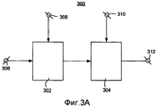
Фиг.3А схематично показывает вариант осуществления блока воспроизведения согласно изобретению, содержащему входной интерфейс для индикации того, какие входные пиксели соответствуют наложению и какие пиксели соответствуют не-наложению;3A schematically shows an embodiment of a reproducing block according to the invention, comprising an input interface for indicating which input pixels correspond to overlay and which pixels correspond to non-overlay;
Фиг.3B схематично показывает вариант осуществления блока воспроизведения согласно изобретению, содержащему блок определения для определения того, какие входные пиксели соответствуют наложению и какие пиксели соответствуют не-наложению;FIG. 3B schematically shows an embodiment of a reproducing unit according to the invention, comprising: a determining unit for determining which input pixels correspond to overlay and which pixels correspond to non-overlay;
Фиг.3C схематично показывает вариант осуществления блока воспроизведения согласно изобретению, содержащему блок установления наложения;FIG. 3C schematically shows an embodiment of a reproduction unit according to the invention, comprising an overlay setting unit;
Фиг.3D схематично показывает вариант осуществления блока воспроизведения согласно изобретению, содержащему блок установления пустой области;3D schematically shows an embodiment of a reproducing unit according to the invention, comprising an empty area establishment unit;
Фиг.4 схематично иллюстрирует вариант осуществления модуля формирования изображения со многими видами; и4 schematically illustrates an embodiment of an image forming module with many views; and
Фиг.5 схематично иллюстрирует вариант осуществления устройства обработки изображения согласно изобретению.5 schematically illustrates an embodiment of an image processing apparatus according to the invention.
Одинаковые числовые ссылочные обозначения используются для обозначения подобных частей на всех чертежах.The same numerical reference designations are used to designate similar parts throughout the drawings.
Фиг.1 схематично иллюстрирует входное изображение 100, соответствующую карту 104 глубины и выходное изображение 102. Входное изображение 100 содержит множество входных пикселей. Входные пиксели могут быть категоризированы в две группы пикселей. Первая группа пикселей содержит пиксели, которые соответствуют наложению. Вторая группа пикселей содержит пиксели, которые соответствуют не-наложению. В качестве наложения предполагается графическое представление, подобное тексту или иконке. Наложение может соответствовать субтитрам, эмблеме канала радиовещания, но альтернативно, наложение соответствует информации на экране дисплея (OSD), которая создана устройством записи или устройством воспроизведения. Наложение может также относиться к графической информации, соответствующей счету в игре. Не-наложение соответствует визуальной информации, которая не имеет наложения. Как правило, не-наложение соответствует данным изображения, которые были захвачены камерой. Альтернативные не-перекрывающиеся данные изображения были созданы посредством графического компьютера, подобные сформированным машиной кинофильмам от "Dreamworks".1 schematically illustrates an input image 100, a corresponding depth map 104, and an output image 102. The input image 100 comprises a plurality of input pixels. Input pixels can be categorized into two groups of pixels. The first group of pixels contains pixels that correspond to the overlay. The second group of pixels contains pixels that correspond to non-overlay. A graphic representation similar to a text or icon is assumed as an overlay. The overlay can correspond to subtitles, the logo of the broadcasting channel, but alternatively, the overlay corresponds to information on a display screen (OSD) that is created by a recording device or a playback device. The overlay can also refer to graphic information corresponding to the score in the game. Non-overlay corresponds to visual information that has no overlay. Typically, non-overlay corresponds to image data that has been captured by the camera. Alternative non-overlapping image data was created by means of a graphic computer, similar to machine-generated motion pictures from "Dreamworks".
Хотя перекрывающиеся и не-перекрывающиеся данные объединены в одиночном входном изображении, обычно не имеется визуального соотношения между ними. Другими словами, значения пикселей, то есть значения цвета и/или яркости первой группы пикселей обычно не связаны со значениями пикселей второй группы пикселей. Как правило, наложение закрывает часть информации, представленной не-наложением во входном изображении.Although overlapping and non-overlapping data are combined in a single input image, there is usually no visual relationship between them. In other words, the pixel values, that is, the color and / or brightness values of the first group of pixels, are usually not related to the pixel values of the second group of pixels. Typically, an overlay covers part of the information represented by a non-overlay in the input image.
Первый один 105 из первой группы пикселей входного изображения 100 принадлежит знаку "t" субтитра. Входное изображение 100 содержит представления первого 106 и второго объекта 108 перед фоном 101. Представление первого объекта 106 имеет овальную форму и содержит первый один 107 из второй группы пикселей. Представление второго объекта 108 имеет прямоугольную форму и содержит второй один 109 из второй группы пикселей.The first one 105 of the first pixel group of the input image 100 belongs to the subtitle “t”. The input image 100 contains representations of the first 106 and the second object 108 in front of the background 101. The representation of the first object 106 is oval and contains the first one 107 of the second group of pixels. The representation of the second object 108 has a rectangular shape and contains the second one 109 of the second group of pixels.
Фиг.1 также схематично изображает карту 104 глубины. Карта 104 глубины есть двумерная матрица со связанными с глубиной элементами данных, то есть значениями глубины. Количество связанных с глубиной элементов данных карты 104 глубины равно количеству пикселей входного изображения 100. Значения глубины, как изображено на фиг. 1, соответствуют соответствующим значениям пикселей входного изображения 100. Карта 104 глубины содержит первый набор 126 значений глубины, который соответствует представлению первого объекта 106 входного изображения 100, и второй набор 128 значений глубины, который соответствует представлению второго объекта 108 входного изображения 100. Первое одно 127 из значений глубины первого набора 126 значений глубины соответствует первому одному 107 из пикселей представления первого объекта 106, и второе одно 129 из значений глубины второго набора 128 из значений глубины соответствует первому одному 109 из пикселей представления второго объекта 108.1 also schematically depicts a depth map 104. The depth map 104 is a two-dimensional matrix with depth-related data elements, i.e. depth values. The number of depth-related data elements of the depth map 104 is equal to the number of pixels of the input image 100. The depth values, as shown in FIG. 1 correspond to corresponding pixel values of the input image 100. The depth map 104 contains a first set 126 of depth values that corresponds to the representation of the first object 106 of the input image 100, and a second set of 128 depth values that corresponds to the representation of the second object 108 of the input image 100. The first one 127 of the depth values of the first set of 126 depth values corresponds to the first one 107 of the pixels of the representation of the first object 106, and the second one 129 of the depth values of the second set of 128 of the values depth corresponds to the first one 109 of the pixels of the representation of the second object 108.
Фиг.1 далее схематично показывает выходное изображение 102, содержащее дальнейшее (последующее) представление первого объекта 116 и дальнейшее представление второго объекта 118. Дальнейшее представление первого объекта 116 основано на представлении первого объекта 106 входного изображения 100, и дальнейшее представление второго объекта 118 основано на представлении второго объекта 108 входного изображения 100. Дальнейшее представление первого объекта 116 вычисляют, смещая соответствующие входные пиксели первого объекта 106 влево. Величина смещения связана с соответствующими значениями глубины первого набора 126 значений глубины. Входное изображение 100 и выходное изображение 102 на фиг. 1 изображены выровненными. Можно видеть с помощью первой пунктирной линии 137, что первый один 107 из пикселей представления первого объекта 106 и соответствующий первый один 117 из пикселей дальнейшего представления первого объекта 116 не имеют взаимно равных координат. Другими словами, соответствующий первый один 117 из пикселей дальнейшего представления первого объекта 116 вычислен посредством смещения первого одного 107 из пикселей представления первого объекта на величину смещения, которая основана на первом одном 127 из значений глубины первого набора 126 значений глубины.1 further schematically shows an output image 102 containing a further (subsequent) representation of a first object 116 and a further representation of a second object 118. A further representation of a first object 116 is based on a representation of a first object 106 of an input image 100, and a further representation of a second object 118 is based on a representation the second object 108 of the input image 100. A further representation of the first object 116 is calculated by shifting the corresponding input pixels of the first object 106 to the left. The offset amount is associated with the corresponding depth values of the first set 126 of depth values. The input image 100 and the output image 102 in FIG. 1 are shown aligned. It can be seen with the help of the first dashed line 137 that the first one 107 of the pixels of the representation of the first object 106 and the corresponding first one of 117 pixels of the further representation of the first object 116 do not have mutually equal coordinates. In other words, the corresponding first one 117 of the pixels of the further representation of the first object 116 is calculated by displacing the first one 107 of the pixels of the representation of the first object by an offset amount that is based on the first one 127 of the depth values of the first set 126 of depth values.
Точно так же, может быть замечено с помощью второй пунктирной линии 139, что первый один 109 из пикселей представления второго объекта 108 и соответствующий первый один 119 из пикселей дальнейшего представления второго объекта 118 не имеет взаимно равных координат. Другими словами, соответствующий первый один 119 из пикселей дальнейшего представления второго объекта 118 вычислен посредством смещения первого одного 109 из пикселей представления второго объекта на величину смещения, которая основана на первом одном 129 из значений глубины второго набора 128 значений глубины.Similarly, it can be seen with the help of the second dashed line 139 that the first one 109 of the pixels of the representation of the second object 108 and the corresponding first one of 119 pixels of the further representation of the second object 118 does not have mutually equal coordinates. In other words, the corresponding first one 119 of the pixels of the further representation of the second object 118 is calculated by displacing the first one 109 of the pixels of the representation of the second object by the offset amount, which is based on the first one 129 of the depth values of the second set 128 of the depth values.
Глядя на пиксели, соответствующие наложению, представляющему слово "text", можно видеть, что смещение не применяется к входным пикселям, представляющим это наложение. Например, первый один 105 из первой группы пикселей входного изображения 100, принадлежащий знаку "t", и соответствующий выходной пиксель 115 имеют взаимно равные координаты. Третья пунктирная линия 135 ясно указывает, что никакого смещения не применено. Другими словами, слово "текст" и во входном изображении 100 и выходном изображении 102 расположено с одними и теми же самыми координатами. Следует обратить внимание, что значения глубины, соответствующие первой группе пикселей, то есть принадлежащие к соответствующим входным пикселям, представляющим слово "text", в качестве доступных в карте 104 глубины, не являются взаимно равными. Фактически они все не равны нулю, приводя к тому результату, что смещение не должно быть применено. Причина того, что пиксели первой группы пикселей фактически являются не смещенными для создания выходного изображения 102, заключается в том, чтобы необходимо сохранить резкое наложение согласно изобретению.Looking at the pixels corresponding to the overlay representing the word "text", you can see that the offset does not apply to the input pixels representing this overlay. For example, the first one 105 of the first group of pixels of the input image 100 belonging to the sign "t" and the corresponding output pixel 115 have mutually equal coordinates. The third dashed line 135 clearly indicates that no offset has been applied. In other words, the word “text” in both the input image 100 and the output image 102 is located with the same coordinates. It should be noted that the depth values corresponding to the first group of pixels, that is, those belonging to the corresponding input pixels representing the word "text", as the depths available in the map 104, are not mutually equal. In fact, they are all non-zero, leading to the result that the offset should not be applied. The reason that the pixels of the first group of pixels are actually not biased to create the output image 102 is because it is necessary to maintain a sharp overlap according to the invention.
Фиг.2 схематично изображает отображение входных пикселей 200 на выходные пиксели 204. Фиг. 2 схематично изображает ряд входных пикселей 200. Имеется первая группа входных пикселей, которые изображены с кружками и которые обозначены заглавными буквами J-M. Первая группа входных пикселей соответствует наложению. Имеется вторая группа входных пикселей, которые изображены с прямоугольниками и обозначены заглавными буквами A-I,N-Q. Вторая группа входных пикселей соответствует не-наложению.FIG. 2 schematically depicts a mapping of input pixels 200 to output pixels 204. FIG. 2 schematically depicts a series of input pixels 200. There is a first group of input pixels, which are depicted with circles and which are indicated by capital letters J-M. The first group of input pixels corresponds to an overlay. There is a second group of input pixels, which are shown with rectangles and are denoted by the capital letters A-I, N-Q. The second group of input pixels corresponds to non-overlay.
Величины смещения 202, которые должны быть применены к соответствующим входным пикселям 200, обозначены числовыми значениями (4 и 0) над прямоугольниками и кружками. Различные стрелки на фиг. 2 представляют величины смещения и отображения от входных пикселей на выходные пиксели.The offset values 202 to be applied to the corresponding input pixels 200 are indicated by numerical values (4 and 0) above the rectangles and circles. The various arrows in FIG. 2 represent displacement and display values from input pixels to output pixels.
Фиг.2 схематично изображает ряд выходных пикселей 204. Имеется первая группа выходных пикселей, которые изображены с кружками, и которые обозначены маленькими буквами j-m. Имеется вторая группа выходных пикселей, которые изображены с прямоугольниками и которые обозначены маленькими буквами a-e, n1-n4.Figure 2 schematically depicts a series of output pixels 204. There is a first group of output pixels, which are shown with circles, and which are indicated by small letters j-m. There is a second group of output pixels, which are shown with rectangles and which are indicated by the small letters a-e, n1-n4.
В выходном изображении 204 имеется область 206 наложения. Можно видеть, что первый один J первой группы входных пикселей должен быть отображен, и первый один F второй группы входных пикселей должен быть смещен к одному и тому же местоположению в выходном изображении. То же самое справедливо для следующих пар входных пикселей: K и G; L и H; М и I. В конечном счете выбранные выходные пиксели обозначены j, k, l и m, соответственно. Это означает, что значения различных выходных пикселей основаны на соответствующих значениях первой группы входных пикселей, то есть входных пикселях, соответствующих наложению. Вариант осуществления блока 303 воспроизведения согласно изобретению, как раскрыто со ссылками на фиг. 3C, выполнен с возможностью установить, что имеется область наложения, и выполнить выбор соответствующих входных пикселей для того, чтобы вычислить соответствующие выходные пиксели.In the output image 204, there is an overlay area 206. It can be seen that the first one J of the first group of input pixels should be displayed, and the first one F of the second group of input pixels should be offset to the same location in the output image. The same is true for the following pairs of input pixels: K and G; L and H; M and I. Ultimately, the selected output pixels are denoted by j, k, l, and m, respectively. This means that the values of the various output pixels are based on the corresponding values of the first group of input pixels, that is, the input pixels corresponding to the overlay. An embodiment of a reproducing
В выходном изображении 204 имеется пустая область 208. Это означает, что ни один из пикселей первой группы пикселей не должен быть отображен и ни один из пикселей второй группы пикселей не должен быть смещен к этой пустой области 208, принимая во внимание координаты входных пикселей и соответствующие величины смещения. Должно быть ясно, что без назначения значения конкретному выходному пикселю существует "дыра" или промежуток. Поскольку это не приемлемо, необходимы дополнительные меры, чтобы предотвратить появление этого случая. Как может быть выведено из фиг. 2, значение пикселя конкретного входного пикселя N второй группы пикселей применяется для вычисления пиксельных значений выходных пикселей n1-n4, которые расположены в пустой области. Пиксельные значения выходных пикселей n1-n4 все основаны на конкретном входном пикселе N, который расположен относительно близко к краевому пикселю М, который расположен на границе наложения. В этом приведенном примере конкретный входной пиксель N соответствует входному пикселю, имеющему минимальное расстояние к краевому пикселю М. Должно быть ясно, что другой входной пиксель с большим расстоянием, например, входной пиксель, обозначенный O, выбран для описанной цели или множества пикселей, например, экстраполированные из P-O-N в пустую область. Вариант осуществления блока 305 воспроизведения согласно изобретению, как раскрыто со ссылками на фиг.3D, выполнен с возможностью установить, что имеется пустая область 208, и выполнить выбор соответствующих входных пикселей для вычисления соответствующих выходных пикселей.The output image 204 has an empty area 208. This means that none of the pixels of the first group of pixels should be displayed and none of the pixels of the second group of pixels should be offset to this empty area 208, taking into account the coordinates of the input pixels and the corresponding displacement values. It should be clear that without assigning a value to a particular output pixel, there is a “hole” or gap. Since this is not acceptable, additional measures are needed to prevent this from occurring. As can be inferred from FIG. 2, the pixel value of a specific input pixel N of the second group of pixels is used to calculate the pixel values of the output pixels n1-n4, which are located in an empty area. The pixel values of the output pixels n1-n4 are all based on a particular input pixel N, which is located relatively close to the edge pixel M, which is located on the overlay border. In this example, a particular input pixel N corresponds to an input pixel having a minimum distance to the edge pixel M. It should be clear that another input pixel with a large distance, for example, an input pixel indicated by O, is selected for the described target or a plurality of pixels, for example, extrapolated from PON to an empty area. An embodiment of the reproducing
Фиг.3А схематично показывает вариант осуществления блока 300 воспроизведения согласно изобретению. Блок 300 воспроизведения выполнен с возможностью воспроизводить выходное изображение 102, содержащее выходные пиксели 115, 117, 119 на основании входного изображения 100, содержащего входные пиксели 105, 107 109 и на основании связанных с глубиной элементов данных 127, 125, 129, соответствующих соответствующим входным пикселям 105, 107, 109.3A schematically shows an embodiment of a reproducing
Блок 300 воспроизведения содержит:Block 300 playback contains:
- блок 302 вычисления смещения для вычисления значения смещения, подлежащего применению к входным пикселям 105, 107, 109, на основании соответствующих связанных с глубиной элементов 127, 125, 129 данных; иan offset
- блок 304 интерполяции для вычисления выходных пикселей 115, 117, 119 на основании смещения входных пикселей 105, 107, 109 на соответствующие значения смещения.an
Блок 300 воспроизведения дополнительно содержит:Block 300 playback further comprises:
- первый входной соединитель 308 для подачи связанных с глубиной элементов данных на блок 302 вычисления смещения;a
- второй входной соединитель 306 для подачи информации, относящейся к наложению/не-наложению, предпочтительно в форме карты индикаторов наложения. Карта индикаторов наложения содержит для каждого из входных пикселей 105, 107, 109 соответствующий индикатор для индикации, соответствует ли входной пиксель наложению или не-наложению; и- a
- третий входной соединитель 310 для подачи пиксельных значений входных пикселей 105, 107, 109 на модуль 304 интерполяции.a
Работа блока 300 воспроизведения заключается в следующем. Для каждого из поданных входных пикселей 105, 107, 109 соответствующие смещения вычисляют на основании соответствующих связанных с глубиной элементов данных 127, 125, 129 блоком 302 вычисления смещения. Вычисленные смещения подают на модуль 304 интерполяции, который выполнен с возможностью вычислять значения выходных пикселей, фактически применяя вычисленные смещения к соответствующим входным пикселям. Значения вычисленных выходных пикселей подаются на выходной соединитель 312.The operation of the
Блок 300 воспроизведения выполнен с возможностью проводить различие между входными пикселями, которые соответствуют наложению и которые соответствуют не-наложению. Это означает, что для входных пикселей, которые соответствуют не-наложению, соответствующие смещения основаны на соответствующих связанных с глубиной элементах данных. Однако, для входных пикселей, которые соответствуют наложению, соответствующие смещения равны нулю. Это означает, что блок 302 вычисления смещения выполнен с возможностью выдавать нуль в качестве выходного значения, если соответствующие входные пиксели соответствуют наложению, независимо от соответствующих связанных с глубиной элементов данных входных пикселей. Необязательно, соответствующие смещения приблизительно равны нулю, если, например, по причинам точности смещение, точно равное нулю, может привести к артефактам.The reproducing
Блок 302 вычисления смещения и блок 304 интерполяции могут быть осуществлены, используя один процессор. Обычно, эти функции выполнены под управлением программного продукта. Во время выполнения программный продукт обычно загружается в память, такую как ОЗУ, и выполняется из нее. Программа может быть загружена из низкоприоритетной памяти, такой как ПЗУ, жесткий диск, или магнитное и/или оптическое запоминающее устройство, или может быть загружена через сеть, подобной Интернет. Необязательно, специализированная интегральная схема обеспечивает раскрытые функциональные возможности.An offset
Должно быть отмечено, что конкретный выходной пиксель может быть основан на одиночном входном пикселе посредством смещения одиночного входного пикселя вектором, имеющим целочисленную длину, относящуюся к структуре отсчетов входного изображения. Однако, обычно величина смещения не имеет целочисленной длины. В таком случае конкретный выходной пиксель основан на взвешенном среднем значении множества входных пикселей, посредством чего взвешивание, например, основано на дробной части величины смещения или другой фильтрующей функции.It should be noted that a particular output pixel can be based on a single input pixel by offsetting the single input pixel by a vector having an integer length related to the sample structure of the input image. However, usually the offset value does not have an integer length. In this case, the specific output pixel is based on a weighted average of the plurality of input pixels, whereby the weighting, for example, is based on the fractional part of the offset value or other filtering function.
Фиг.3B схематично показывает вариант осуществления блока 301 воспроизведения согласно изобретению, содержащему блок 309 определения для определения, какие входные пиксели соответствуют наложению и какие пиксели соответствуют не-наложению. Этот вариант осуществления блока 301 воспроизведения по существу эквивалентен модулю 300 воспроизведения, как описано со ссылками на фиг.3A. Отличие заключается в том, что информация, относительно того, какой из входных пикселей соответствует наложению и какой соответствуют не-наложению, не является определенной и подаваемой извне, а определяется в блоке 301 воспроизведения. Такой блок определения известен специалисту, например, из статьи "General and domain- specific techniques for detecting and recognized superimposed text in video", by D. Zhang, R, K. Rajendran, and S-F. Chang, в трудах IEEE ICIP (International Conference on Image Processing), Rochester, NY, USA, Sept. 2002 или из статьи "Detection of TV commercials", Alberto Albiol, Maria Jose Ch. Fulla, Antonio Albiol & Luis Torres, см. стр. 2-3, часть 2: "logo mask extraction."FIG. 3B schematically shows an embodiment of a reproducing
Блок302 вычисления смещения, блок 304 интерполяции и блок 309 определения могут быть осуществлены, используя один процессор.An offset
Фиг.3C схематично показывает вариант осуществления блока 303 воспроизведения согласно изобретению, содержащему блок 314 установления наложения и первый модуль 316 выбора. Этот вариант осуществления блока 303 воспроизведения по существу эквивалентен модулю 300 воспроизведения, как описано со ссылками на фиг. 3A. Отличие заключается в том, что блок 303 воспроизведения согласно этому варианту осуществления выполнен с возможностью позволять входным пикселям, которые соответствуют наложению, преобладать над входными пикселями, которые соответствуют не-наложению в случае области наложения. Этот вариант осуществления блока 303 воспроизведения содержит:FIG. 3C schematically shows an embodiment of a
- блок 314 установления наложения для установления, на основании части связанных с глубиной элементов данных, имеется ли область наложения в выходном изображении, на которую первый один J из первой группы пикселей должен быть отображен, и первый один F из второй группы пикселей должен быть смещен; и- an
- первый блок выбора 316 для выбора первого одного из J первой группы пикселей для вычисления второго одного j из выходных пикселей, расположенных в области 206 наложения.- a
Работа и преимущество такого установления и выбора объясняются со ссылками на фиг. 2.The operation and advantage of such establishment and selection are explained with reference to FIG. 2.
Альтернативно, блок 303 воспроизведения также содержит блок 309 определения, как объяснено со ссылками на фиг. 3B.Alternatively, the reproducing
Блок 302 вычисления смещения, блок 304 интерполяции, блок 309 определения, блок 314 установления наложения и первый блок 316 выбора могут быть осуществлены, используя один процессор.An offset
Фиг.3D схематично показывает вариант осуществления блока 305 воспроизведения согласно изобретению, содержащему блок 318 установления пустой области и соответствующий модуль 320 выбора. Этот вариант осуществления блока 305 воспроизведения по существу эквивалентен модулю 300 воспроизведения, описанному со ссылками на фиг. 3A. Отличие заключается в том, что блок 305 воспроизведения согласно этому варианту осуществления выполнен с возможностью позволять входным пикселям, которые соответствуют не-наложению, преобладать над входными пикселями, которые соответствуют наложению в случае пустой области 208. Этот вариант осуществления блока 305 воспроизведения содержит:3D schematically shows an embodiment of a reproducing
- блок 318 установления пустой области для установления, на основании дополнительной части связанных с глубиной элементов данных, имеется ли пустая область 208 в выходном изображении, на которую ни один из пикселей первой группы пикселей не должен быть отображен и на которую ни один из пикселей второй группы пикселей не должен быть смещен; и- block 318 establishing an empty area for determining, based on an additional part related to the depth of the data elements, is there an empty area 208 in the output image onto which none of the pixels of the first group of pixels should be displayed and on which none of the pixels of the second group pixels should not be offset; and
- второй блок 320 выбора для выбора конкретного одного из второй группы пикселей для вычисления третьего одного из выходных пикселей, расположенных в пустой области.- a
Работа и преимущество такого установления и выбора объясняются со ссылками на фиг. 2.The operation and advantage of such establishment and selection are explained with reference to FIG. 2.
Альтернативно, блок 305 воспроизведения также содержит блок 309 определения, как объяснено со ссылками на фиг. 3B.Alternatively, the reproducing
Альтернативно, блок 305 воспроизведения также содержит блок 314 установления наложения и первый блок 316 выбора, как объяснено со ссылками на фиг. 3C.Alternatively, the reproducing
Блок 302 вычисления смещения, блок 304 интерполяции, блок 309 определения, блок 314 установления наложения, первый блок 316 выбора, блок 318 установления пустой области и второй блок 320 выбора могут быть осуществлены, используя один процессор.An offset
Фиг.4 схематично изображает вариант осуществления модуля 400 формирования изображения со многими видами, содержащего вариант осуществления блока 402 воспроизведения согласно изобретению, как описано со ссылками на любую из Фиг. 3A-3D. Блок 400 формирования изображения со многими видами выполнен с возможностью формировать последовательность изображений со многими видами на основании последовательности изображений видео. Блок 400 формирования изображения со многими видами снабжается потоком изображений видео на входной соединитель 406 и выдает два коррелированных потока изображений видео на выходных соединителях 412 и 414 соответственно. Эти два коррелированных потока изображений видео должны быть поданы к устройству отображения со многими видами, которое выполнено с возможностью визуализировать первую последовательность видов на основании первого одного из коррелированных потоков изображений видео и визуализировать вторую последовательность видов на основании второго одного из коррелированных потоков изображений видео. Если пользователь, то есть наблюдатель, наблюдает первую последовательность видов своим левым глазом и вторую последовательность видов своим правым глазом, он замечает трехмерное восприятие. Может быть случай, что первый один из коррелированных потоков изображений видео соответствует последовательности изображений видео как принята, и что второй один из коррелированных потоков изображений видео воспроизводится согласно способу изобретения на основании последовательности изображений видео как принята. Предпочтительно, оба потока изображений видео воспроизводятся согласно способу изобретения на основании последовательности изображений видео как принята.FIG. 4 schematically depicts an embodiment of a multi-view
Блок 400 формирования изображения со многими видами дополнительно содержит первый входной соединитель 408 для подачи связанных с глубиной элементов данных и второй входной соединитель 410 для подачи информации, касающейся наложения/не-наложения предпочтительно в форме карты индикаторов наложения.The
Должно быть отмечено, что хотя блок 400 формирования изображения со многими видами предназначен, чтобы иметь дело с изображениями видео, альтернативные варианты осуществления модуля 400 формирования изображения со многими видами выполнены с возможностью формировать изображение со многими видами на основании индивидуальных изображений, то есть фотоснимков.It should be noted that although the multi-view
Должно быть отмечено, что хотя изображенный блок 400 формирования изображения со многими видами имеет два выходных соединителя 412 и 414, альтернативные пути выдачи возможны, например чередуемый выход, который готов выполнять отображение на устройстве отображения со многими видами. Помимо этого, ряд выходных изображений, формирующих различные изображения со многими видами, конечно, не ограничивается количеством из двух.It should be noted that although the depicted
Фиг.5 схематично иллюстрирует вариант осуществления устройства 500 обработки изображения согласно изобретению, содержащего:5 schematically illustrates an embodiment of an
- блок 502 приема для приема сигнала видео, представляющего входные изображения и связанные с глубиной данные;- a
- блок 400 формирования изображения со многими видами для формирования изображений со многими видами на основании принятых входных изображений и соответствующих связанных с глубиной элементов данных, как описано со ссылками на фиг. 4; иa multi-view
- устройство 506 отображения со многими видами для отображения изображений со многими видами, как обеспечивается модулем 400 формирования изображения со многими видами.- a
Сигнал видео может быть радиовещательным сигналом, принятым через антенну или кабель, но может также быть сигналом от запоминающего устройства, такого как VCR (кассетный видеомагнитофон) или цифровой универсальный диск (DVD). Сигнал подается на входной соединитель 510. Устройство 500 обработки изображения может быть, например, телевизором. Альтернативно, устройство 500 обработки изображения не содержит необязательного устройства отображения, но выдает выходные изображения к устройству, которое как раз содержит устройство 506 отображения. Кроме того, устройство 500 обработки изображения может быть, например, телевизионной приставкой, спутниковым тюнером, видеомагнитофоном, устройством записи или воспроизведения DVD. Необязательно, устройство 500 обработки изображения содержит средство хранения, подобное жесткому диску, или средство для хранения на сменных носителях, например, оптических дисках. Устройство 500 обработки изображения может также быть системой, применяемой киностудией или радио или телевизионной вещательной станцией.The video signal may be a broadcast signal received through an antenna or cable, but may also be a signal from a storage device such as a VCR (VCR) or digital versatile disc (DVD). The signal is supplied to an
Должно быть отмечено, что вышеупомянутые варианты осуществления не иллюстрируют ограничения изобретения, и что специалисты в данной области техники способны создавать альтернативные варианты осуществления без отрыва от объема приложенной формулы изобретения. В формуле изобретения любые ссылочные позиции, указанные в круглых скобках, не должны рассматриваться как ограничение пункта формулы. Слово "содержащий" не исключает присутствие элементов или этапов, не перечисленных в пункте формулы. Неопределенный артикль "a" или "an", предшествующий элементу, не исключает присутствие множества таких элементов. Изобретение может быть осуществлено посредством аппаратных средств, содержащих несколько отличных элементов, и посредством подходящего запрограммированного компьютера. В пунктах формулы изобретения на устройство, перечисляющих несколько средств, несколько из этих средств могут быть воплощены одним и тем же элементом аппаратных средств. Использование слов "первый", "второй" и "третий" "и т.д." не указывает какого-либо упорядочение. Эти слова должны интерпретироваться как названия.It should be noted that the above embodiments do not illustrate the limitations of the invention, and that those skilled in the art are capable of creating alternative embodiments without departing from the scope of the appended claims. In the claims, any reference numerals indicated in parentheses should not be construed as limiting the claims. The word “comprising” does not exclude the presence of elements or steps not listed in a claim. The indefinite article "a" or "an" preceding an element does not exclude the presence of many such elements. The invention may be practiced by means of hardware containing several excellent elements, and by means of a suitable programmed computer. In the claims of a device listing several means, several of these means may be embodied by the same hardware element. Use of the words "first", "second" and "third", "etc." does not indicate any ordering. These words should be interpreted as names.
Claims (12)
блок (302) вычисления смещения для вычисления значений смещения, подлежащих применению к входным пикселям, на основании соответствующих связанных с глубиной элементов данных; и
блок (304) интерполяции для вычисления выходных пикселей на основании смещения входных пикселей на соответствующие значения смещения, отличающийся тем, что блок (302) вычисления смещения выполнен с возможностью выдавать выходное значение в качестве первого одного из значений смещения, которое, по существу, равно нулю, если соответствующий первый один из входных пикселей соответствует наложению независимо от соответствующего связанного с глубиной элемента данных.1. A reproducing apparatus (300) for reproducing an output image (102) containing output pixels based on an input image (100) containing input pixels and based on depth-related data elements corresponding to respective input pixels, wherein the device (300 ) playback contains:
an offset calculating unit (302) for calculating the offset values to be applied to the input pixels based on the corresponding depth-related data elements; and
an interpolation unit (304) for calculating the output pixels based on the offset of the input pixels by the corresponding offset values, characterized in that the offset calculation unit (302) is configured to output the output value as the first one of the offset values, which is essentially zero if the corresponding first one of the input pixels corresponds to an overlay regardless of the corresponding depth-related data element.
блок (314) установления наложения для установления на основании части связанных с глубиной элементов данных, имеется ли область наложения в выходном изображении, на которую первый один из первой группы пикселей должен быть отображен и первый один из второй группы пикселей должен быть смещен; и
блок (316) выбора для выбора первого одного из первой группы пикселей для вычисления второго одного из выходных пикселей, расположенных в области наложения.4. The playback device (303) according to claim 2 or 3, further comprising:
an overlay setting unit (314) for determining, based on a portion of the depth related data elements, whether there is an overlay area in the output image onto which the first one of the first group of pixels should be displayed and the first one of the second group of pixels should be offset; and
block (316) selection for selecting the first one of the first group of pixels to calculate the second one of the output pixels located in the overlay area.
блок (318) установления пустой области для установления на основании дополнительной части связанных с глубиной элементов данных, имеется ли пустая область в выходном изображении, на которую ни один из пикселей первой группы пикселей не должен быть отображен и на которую ни один из пикселей второй группы пикселей не должен быть смещен; и
блок (320) выбора для выбора конкретного одного из второй группы пикселей для вычисления третьего одного из выходных пикселей, расположенных в пустой области.5. The playback device (305) according to claim 2 or 3, further comprising:
block (318) establishing an empty area for determining, based on the additional part related to the depth of the data elements, whether there is an empty area in the output image on which none of the pixels of the first group of pixels should be displayed and on which none of the pixels of the second group of pixels should not be biased; and
a selection unit (320) for selecting a particular one of the second group of pixels for calculating a third one of the output pixels located in the empty area.
блок (318) установления пустой области для установления на основании дополнительной части связанных с глубиной элементов данных, имеется ли пустая область в выходном изображении, на которую ни один из пикселей первой группы пикселей не должен быть отображен и на которую ни один из пикселей второй группы пикселей не должен быть смещен; и
блок (320) выбора для выбора конкретного одного из второй группы пикселей для вычисления третьего одного из выходных пикселей, расположенных в пустой области.7. The playback device (305) according to claim 4, further comprising:
block (318) establishing an empty area for determining, based on the additional part related to the depth of the data elements, whether there is an empty area in the output image on which none of the pixels of the first group of pixels should be displayed and on which none of the pixels of the second group of pixels should not be biased; and
a selection unit (320) for selecting a particular one of the second group of pixels for calculating a third one of the output pixels located in the empty area.
средство (502) приема для приема сигнала, соответствующего входному изображению (100); и
устройство (300) воспроизведения по п.1 для воспроизведения выходного изображения (102).9. An image processing device (500), comprising:
reception means (502) for receiving a signal corresponding to an input image (100); and
a reproducing apparatus (300) according to claim 1 for reproducing an output image (102).
вычисление значений смещения, подлежащих применению к входным пикселям, на основании соответствующих связанных с глубиной элементов данных; и
вычисление выходных пикселей на основании смещения входных пикселей на соответствующие значения смещения, отличающийся тем, что этап вычисления значений смещения приводит к получению выходного значения в качестве первого одного из значений смещения, которое, по существу, равно нулю, если соответствующий первый один из входных пикселей соответствует наложению независимо от соответствующего связанного с глубиной элемента данных.11. Computer-readable media containing computer instructions that, when executed on a computer, force the computer to implement a method for reproducing an output image containing output pixels based on an input image containing input pixels and based on depth-related data elements corresponding to corresponding input pixels and moreover, the method comprises the steps of:
calculating the offset values to be applied to the input pixels based on the corresponding depth-related data elements; and
calculating the output pixels based on the offset of the input pixels by the corresponding offset values, characterized in that the step of calculating the offset values results in an output value as the first one of the offset values, which is essentially zero if the corresponding first one of the input pixels corresponds to overlay regardless of the corresponding depth-related data item.
вычисление значений смещения, подлежащих применению к входным пикселям, на основании соответствующих связанных с глубиной элементов данных и
вычисление выходных пикселей на основании смещения входных пикселей на соответствующие значения смещения, отличающийся тем, что этап вычисления значений смещения приводит к получению выходного значения в качестве первого одного из значений смещения, которое, по существу, равно нулю, если соответствующий первый один из входных пикселей соответствует наложению независимо от соответствующего связанного с глубиной элемента данных. 12. A method of reproducing an output image containing output pixels based on an input image containing input pixels and based on depth-related data elements corresponding to respective input pixels, the method comprising the steps of:
calculating the offset values to be applied to the input pixels based on the corresponding depth-related data elements and
calculating the output pixels based on the offset of the input pixels by the corresponding offset values, characterized in that the step of calculating the offset values results in an output value as the first one of the offset values, which is essentially zero if the corresponding first one of the input pixels corresponds to overlay regardless of the corresponding depth-related data item.
Applications Claiming Priority (2)
| Application Number | Priority Date | Filing Date | Title |
|---|---|---|---|
| EP05103121.9 | 2005-04-19 | ||
| EP05103121 | 2005-04-19 |
Publications (2)
| Publication Number | Publication Date |
|---|---|
| RU2007142457A RU2007142457A (en) | 2009-05-27 |
| RU2407224C2 true RU2407224C2 (en) | 2010-12-20 |
Family
ID=36716939
Family Applications (1)
| Application Number | Title | Priority Date | Filing Date |
|---|---|---|---|
| RU2007142457/09A RU2407224C2 (en) | 2005-04-19 | 2006-04-12 | Depth perception |
Country Status (8)
| Country | Link |
|---|---|
| US (1) | US8013873B2 (en) |
| EP (1) | EP1875440B1 (en) |
| JP (2) | JP2008537250A (en) |
| CN (1) | CN100576251C (en) |
| AT (1) | ATE416443T1 (en) |
| DE (1) | DE602006004033D1 (en) |
| RU (1) | RU2407224C2 (en) |
| WO (1) | WO2006111893A1 (en) |
Cited By (2)
| Publication number | Priority date | Publication date | Assignee | Title |
|---|---|---|---|---|
| RU2788439C2 (en) * | 2017-10-06 | 2023-01-19 | ИНТЕРДИДЖИТАЛ ВиСи ХОЛДИНГЗ, ИНК. | Method and device for generation of points of three-dimensional (3d) scene |
| US11830210B2 (en) | 2017-10-06 | 2023-11-28 | Interdigital Vc Holdings, Inc. | Method and device for generating points of a 3D scene |
Families Citing this family (56)
| Publication number | Priority date | Publication date | Assignee | Title |
|---|---|---|---|---|
| JP5132690B2 (en) | 2007-03-16 | 2013-01-30 | トムソン ライセンシング | System and method for synthesizing text with 3D content |
| EP2201784B1 (en) * | 2007-10-11 | 2012-12-12 | Koninklijke Philips Electronics N.V. | Method and device for processing a depth-map |
| EP3454549B1 (en) | 2008-07-25 | 2022-07-13 | Koninklijke Philips N.V. | 3d display handling of subtitles |
| US9357231B2 (en) | 2008-07-31 | 2016-05-31 | Mitsubishi Electric Corporation | Video encoding device, video encoding method, video reproducing device, video reproducing method, video recording medium, and video data stream |
| WO2010046824A1 (en) * | 2008-10-21 | 2010-04-29 | Koninklijke Philips Electronics N.V. | Method and system for processing an input three dimensional video signal |
| RU2512135C2 (en) * | 2008-11-18 | 2014-04-10 | Панасоник Корпорэйшн | Reproduction device, reproduction method and programme for stereoscopic reproduction |
| US8335425B2 (en) * | 2008-11-18 | 2012-12-18 | Panasonic Corporation | Playback apparatus, playback method, and program for performing stereoscopic playback |
| EP2320667A1 (en) * | 2009-10-20 | 2011-05-11 | Koninklijke Philips Electronics N.V. | Combining 3D video auxiliary data |
| EP2374280A1 (en) * | 2008-11-24 | 2011-10-12 | Koninklijke Philips Electronics N.V. | Combining 3d video and auxiliary data |
| GB2467932A (en) | 2009-02-19 | 2010-08-25 | Sony Corp | Image processing device and method |
| KR20100128233A (en) * | 2009-05-27 | 2010-12-07 | 삼성전자주식회사 | Method and apparatus for processing video image |
| TW201119353A (en) | 2009-06-24 | 2011-06-01 | Dolby Lab Licensing Corp | Perceptual depth placement for 3D objects |
| US9215435B2 (en) | 2009-06-24 | 2015-12-15 | Dolby Laboratories Licensing Corp. | Method for embedding subtitles and/or graphic overlays in a 3D or multi-view video data |
| JP5407968B2 (en) * | 2009-06-29 | 2014-02-05 | ソニー株式会社 | Stereoscopic image data transmitting apparatus and stereoscopic image data receiving apparatus |
| JP5402715B2 (en) * | 2009-06-29 | 2014-01-29 | ソニー株式会社 | Stereo image data transmitting apparatus, stereo image data transmitting method, stereo image data receiving apparatus, and stereo image data receiving method |
| JP5429034B2 (en) * | 2009-06-29 | 2014-02-26 | ソニー株式会社 | Stereo image data transmitting apparatus, stereo image data transmitting method, stereo image data receiving apparatus, and stereo image data receiving method |
| JP2011030182A (en) * | 2009-06-29 | 2011-02-10 | Sony Corp | Three-dimensional image data transmission device, three-dimensional image data transmission method, three-dimensional image data reception device, and three-dimensional image data reception method |
| JP2011030180A (en) * | 2009-06-29 | 2011-02-10 | Sony Corp | Three-dimensional image data transmission device, three-dimensional image data transmission method, three-dimensional image data reception device, and three-dimensional image data reception method |
| TW201116041A (en) * | 2009-06-29 | 2011-05-01 | Sony Corp | Three-dimensional image data transmission device, three-dimensional image data transmission method, three-dimensional image data reception device, three-dimensional image data reception method, image data transmission device, and image data reception |
| JP5407957B2 (en) * | 2009-06-29 | 2014-02-05 | ソニー株式会社 | Stereoscopic image data transmitting apparatus and stereoscopic image data receiving apparatus |
| JP2011030179A (en) * | 2009-06-29 | 2011-02-10 | Sony Corp | Image data transmission device, control method and program |
| JP5521486B2 (en) * | 2009-06-29 | 2014-06-11 | ソニー株式会社 | Stereoscopic image data transmitting apparatus and stereoscopic image data transmitting method |
| JP5446913B2 (en) * | 2009-06-29 | 2014-03-19 | ソニー株式会社 | Stereoscopic image data transmitting apparatus and stereoscopic image data transmitting method |
| GB2473282B (en) * | 2009-09-08 | 2011-10-12 | Nds Ltd | Recommended depth value |
| EP2309463A3 (en) * | 2009-10-07 | 2011-07-27 | Thomson Licensing | Method of displaying a 3D video with insertion of a graphic item and terminal for implementing the method |
| KR101637491B1 (en) * | 2009-12-30 | 2016-07-08 | 삼성전자주식회사 | Method and apparatus for generating 3D image data |
| US9398289B2 (en) * | 2010-02-09 | 2016-07-19 | Samsung Electronics Co., Ltd. | Method and apparatus for converting an overlay area into a 3D image |
| US9426441B2 (en) | 2010-03-08 | 2016-08-23 | Dolby Laboratories Licensing Corporation | Methods for carrying and transmitting 3D z-norm attributes in digital TV closed captioning |
| US8817072B2 (en) | 2010-03-12 | 2014-08-26 | Sony Corporation | Disparity data transport and signaling |
| CN102845067B (en) * | 2010-04-01 | 2016-04-20 | 汤姆森许可贸易公司 | Captions during three-dimensional (3D) presents |
| JP5143856B2 (en) | 2010-04-16 | 2013-02-13 | 株式会社ソニー・コンピュータエンタテインメント | 3D image display device and 3D image display method |
| JP2011249945A (en) * | 2010-05-24 | 2011-12-08 | Sony Corp | Stereoscopic image data transmission device, stereoscopic image data transmission method, stereoscopic image data reception device, and stereoscopic image data reception method |
| KR20130108075A (en) * | 2010-05-30 | 2013-10-02 | 엘지전자 주식회사 | Method and apparatus for processing and receiving digital broadcast signal for 3-dimensional subtitle |
| KR101385514B1 (en) * | 2010-06-08 | 2014-04-16 | 주식회사 에스칩스 | Method And Apparatus for Transforming Stereoscopic Image by Using Depth Map Information |
| JP5627498B2 (en) * | 2010-07-08 | 2014-11-19 | 株式会社東芝 | Stereo image generating apparatus and method |
| CN101902582B (en) * | 2010-07-09 | 2012-12-19 | 清华大学 | Method and device for adding stereoscopic video subtitle |
| EP2596641A4 (en) * | 2010-07-21 | 2014-07-30 | Thomson Licensing | Method and device for providing supplementary content in 3d communication system |
| KR101816846B1 (en) * | 2010-08-19 | 2018-01-12 | 삼성전자주식회사 | Display apparatus and method for providing OSD applying thereto |
| US8432392B2 (en) | 2010-09-02 | 2013-04-30 | Samsung Electronics Co., Ltd. | Display system with image conversion mechanism and method of operation thereof |
| US8571314B2 (en) | 2010-09-02 | 2013-10-29 | Samsung Electronics Co., Ltd. | Three-dimensional display system with depth map mechanism and method of operation thereof |
| US8610759B2 (en) * | 2010-10-26 | 2013-12-17 | Verizon Patent And Licensing Inc. | Methods and systems for presenting adjunct content during a presentation of a media content instance |
| US8553071B2 (en) * | 2010-10-26 | 2013-10-08 | Verizon Patent And Licensing, Inc. | Methods and systems for presenting adjunct content during a presentation of a media content instance |
| GB2485140A (en) * | 2010-10-26 | 2012-05-09 | Sony Corp | A Method and Apparatus For Inserting Object Data into a Stereoscopic Image |
| JP2012100102A (en) * | 2010-11-02 | 2012-05-24 | Sony Corp | Stereoscopic image data transmission device, stereoscopic image data transmission method, stereoscopic image data reception device, and stereoscopic image data reception method |
| JP5036088B2 (en) * | 2011-01-14 | 2012-09-26 | シャープ株式会社 | Stereoscopic image processing apparatus, stereoscopic image processing method, and program |
| TR201103444A2 (en) * | 2011-04-08 | 2012-10-22 | Vestel Elektron�K Sanay� Ve T�Caret A.�. | Method and device for creating a 3D image from a 2D image. |
| US9519994B2 (en) | 2011-04-15 | 2016-12-13 | Dolby Laboratories Licensing Corporation | Systems and methods for rendering 3D image independent of display size and viewing distance |
| AU2012291320A1 (en) * | 2011-08-04 | 2013-03-14 | Sony Corporation | Transmission device, transmission method, and receiving device |
| JP2013066075A (en) * | 2011-09-01 | 2013-04-11 | Sony Corp | Transmission device, transmission method and reception device |
| CN103842907A (en) * | 2011-09-30 | 2014-06-04 | 富士胶片株式会社 | Imaging device for three-dimensional image and image display method for focus state confirmation |
| JP6092525B2 (en) * | 2012-05-14 | 2017-03-08 | サターン ライセンシング エルエルシーSaturn Licensing LLC | Image processing apparatus, information processing system, image processing method, and program |
| KR102076598B1 (en) * | 2013-05-24 | 2020-03-02 | 삼성전자주식회사 | Display apparatus and method for displaying multi view image using the same |
| US9369727B2 (en) * | 2014-07-10 | 2016-06-14 | Intel Corporation | Storage of depth information in a digital image file |
| US9449414B1 (en) | 2015-03-05 | 2016-09-20 | Microsoft Technology Licensing, Llc | Collaborative presentation system |
| GB2568476B (en) | 2017-11-15 | 2020-02-19 | Advanced Risc Mach Ltd | Method of image production |
| US10937362B1 (en) * | 2019-09-23 | 2021-03-02 | Au Optronics Corporation | Electronic apparatus and operating method thereof |
Family Cites Families (34)
| Publication number | Priority date | Publication date | Assignee | Title |
|---|---|---|---|---|
| US5204916A (en) * | 1991-08-06 | 1993-04-20 | Eastman Kodak Company | Tile-oriented technique for collectively performing image rotation, scaling and digital halftone screening |
| RU2116704C1 (en) | 1991-12-23 | 1998-07-27 | Олег Кимович Никифоров | Method for generation and viewing stereo image for moving observer and device which implements said method |
| US5499327A (en) * | 1992-01-20 | 1996-03-12 | Canon Kabushiki Kaisha | Multi-window system which can overlay-display a dynamic image in a specific window |
| JPH05197360A (en) * | 1992-01-20 | 1993-08-06 | Canon Inc | Image processing system and method therefor |
| US5565907A (en) * | 1993-04-20 | 1996-10-15 | Ricoh Company, Ltd. | Image forming apparatus capable of producing high quality halftone images |
| TW304254B (en) * | 1994-07-08 | 1997-05-01 | Hitachi Ltd | |
| US5881176A (en) * | 1994-09-21 | 1999-03-09 | Ricoh Corporation | Compression and decompression with wavelet style and binary style including quantization by device-dependent parser |
| US6549666B1 (en) * | 1994-09-21 | 2003-04-15 | Ricoh Company, Ltd | Reversible embedded wavelet system implementation |
| US5838334A (en) * | 1994-11-16 | 1998-11-17 | Dye; Thomas A. | Memory and graphics controller which performs pointer-based display list video refresh operations |
| US5790086A (en) | 1995-01-04 | 1998-08-04 | Visualabs Inc. | 3-D imaging system |
| US6064424A (en) * | 1996-02-23 | 2000-05-16 | U.S. Philips Corporation | Autostereoscopic display apparatus |
| JPH11110180A (en) * | 1997-10-03 | 1999-04-23 | Sanyo Electric Co Ltd | Method and device for converting two-dimensional image into three-dimensional image |
| US6236757B1 (en) * | 1998-06-18 | 2001-05-22 | Sharp Laboratories Of America, Inc. | Joint coding method for images and videos with multiple arbitrarily shaped segments or objects |
| US6185042B1 (en) * | 1998-06-22 | 2001-02-06 | Eastman Kodak Company | Process for increasing the clarity and legibility of graphics, text, and continuous tone composites in lenticular images |
| US6208354B1 (en) * | 1998-11-03 | 2001-03-27 | Ati International Srl | Method and apparatus for displaying multiple graphics images in a mixed video graphics display |
| JP4300650B2 (en) * | 1999-09-07 | 2009-07-22 | ソニー株式会社 | Arithmetic processing circuit and method and image processing apparatus |
| JP4772952B2 (en) * | 2000-08-28 | 2011-09-14 | 株式会社バンダイナムコゲームス | Stereoscopic image generation apparatus and information storage medium |
| JP2002135734A (en) * | 2000-10-19 | 2002-05-10 | Nippon Television Network Corp | Data broadcasting system and its method |
| US7088854B2 (en) * | 2001-04-25 | 2006-08-08 | Cotman Carl W | Method and apparatus for generating special-purpose image analysis algorithms |
| US6778224B2 (en) | 2001-06-25 | 2004-08-17 | Koninklijke Philips Electronics N.V. | Adaptive overlay element placement in video |
| JP4034964B2 (en) * | 2001-12-27 | 2008-01-16 | 株式会社バンダイナムコゲームス | Program, information storage medium, and stereoscopic image generation apparatus |
| EP2387248A3 (en) | 2002-03-27 | 2012-03-07 | Sanyo Electric Co., Ltd. | Method and apparatus for processing three-dimensional images |
| JP2003284093A (en) * | 2002-03-27 | 2003-10-03 | Sanyo Electric Co Ltd | Stereoscopic image processing method and apparatus therefor |
| US7227893B1 (en) * | 2002-08-22 | 2007-06-05 | Xlabs Holdings, Llc | Application-specific object-based segmentation and recognition system |
| JP4129786B2 (en) * | 2002-09-06 | 2008-08-06 | ソニー株式会社 | Image processing apparatus and method, recording medium, and program |
| EP1437898A1 (en) * | 2002-12-30 | 2004-07-14 | Koninklijke Philips Electronics N.V. | Video filtering for stereo images |
| JP2004274125A (en) | 2003-03-05 | 2004-09-30 | Sony Corp | Image processing apparatus and method |
| JP3795026B2 (en) * | 2003-03-20 | 2006-07-12 | 株式会社ソフィア | Game machine |
| JP4022173B2 (en) * | 2003-06-02 | 2007-12-12 | 株式会社ソフィア | Game machine |
| EP1503345A1 (en) * | 2003-07-30 | 2005-02-02 | Koninklijke Philips Electronics N.V. | System for adaptive resampling in texture mapping |
| US20050063608A1 (en) * | 2003-09-24 | 2005-03-24 | Ian Clarke | System and method for creating a panorama image from a plurality of source images |
| US7366357B2 (en) * | 2004-02-12 | 2008-04-29 | Xerox Corporation | Systems and methods for adjusting image data to form highly compressible image planes |
| EP1587035A1 (en) * | 2004-04-14 | 2005-10-19 | Koninklijke Philips Electronics N.V. | Ghost artifact reduction for rendering 2.5D graphics |
| US7429993B2 (en) * | 2004-09-17 | 2008-09-30 | Microsoft Corporation | Method and system for presenting functionally-transparent, unobtrusive on-screen windows |
-
2006
- 2006-04-12 WO PCT/IB2006/051140 patent/WO2006111893A1/en active Application Filing
- 2006-04-12 DE DE602006004033T patent/DE602006004033D1/en active Active
- 2006-04-12 RU RU2007142457/09A patent/RU2407224C2/en not_active IP Right Cessation
- 2006-04-12 US US11/911,561 patent/US8013873B2/en not_active Expired - Fee Related
- 2006-04-12 JP JP2008507223A patent/JP2008537250A/en not_active Withdrawn
- 2006-04-12 EP EP06727910A patent/EP1875440B1/en not_active Not-in-force
- 2006-04-12 CN CN200680012969A patent/CN100576251C/en not_active Expired - Fee Related
- 2006-04-12 AT AT06727910T patent/ATE416443T1/en not_active IP Right Cessation
-
2011
- 2011-12-22 JP JP2011281020A patent/JP5406269B2/en not_active Expired - Fee Related
Non-Patent Citations (1)
| Title |
|---|
| REDERT A. et al. Synthesis of multi viewpoint images at non-intermediate positions, ACOUSTICS, SPEECH AND SIGNAL PROCESSING, 1997. ICASSP-97. IEEE COMPUT. SOC, vol.4, 21 April 1997, cc.2749-2752. * |
Cited By (2)
| Publication number | Priority date | Publication date | Assignee | Title |
|---|---|---|---|---|
| RU2788439C2 (en) * | 2017-10-06 | 2023-01-19 | ИНТЕРДИДЖИТАЛ ВиСи ХОЛДИНГЗ, ИНК. | Method and device for generation of points of three-dimensional (3d) scene |
| US11830210B2 (en) | 2017-10-06 | 2023-11-28 | Interdigital Vc Holdings, Inc. | Method and device for generating points of a 3D scene |
Also Published As
| Publication number | Publication date |
|---|---|
| EP1875440A1 (en) | 2008-01-09 |
| WO2006111893A1 (en) | 2006-10-26 |
| JP2008537250A (en) | 2008-09-11 |
| CN101180658A (en) | 2008-05-14 |
| EP1875440B1 (en) | 2008-12-03 |
| DE602006004033D1 (en) | 2009-01-15 |
| CN100576251C (en) | 2009-12-30 |
| US20080192067A1 (en) | 2008-08-14 |
| JP5406269B2 (en) | 2014-02-05 |
| RU2007142457A (en) | 2009-05-27 |
| JP2012108922A (en) | 2012-06-07 |
| ATE416443T1 (en) | 2008-12-15 |
| US8013873B2 (en) | 2011-09-06 |
Similar Documents
| Publication | Publication Date | Title |
|---|---|---|
| RU2407224C2 (en) | Depth perception | |
| US11310486B2 (en) | Method and apparatus for combining 3D image and graphical data | |
| JP4762994B2 (en) | Parallax map | |
| KR101038452B1 (en) | Multi-view image generation | |
| JP5132690B2 (en) | System and method for synthesizing text with 3D content | |
| JP5584292B2 (en) | Incorporating 3D objects into stereoscopic images with relative depth | |
| EP2603834B1 (en) | Method for forming images | |
| US8270768B2 (en) | Depth perception | |
| JP2009528587A (en) | Rendering the output image | |
| JP2010226500A (en) | Device and method for displaying stereoscopic image | |
| US9519994B2 (en) | Systems and methods for rendering 3D image independent of display size and viewing distance | |
| JP4908624B1 (en) | 3D image signal processing apparatus and method | |
| JP4991930B2 (en) | 3D image signal processing apparatus and method | |
| KR20150012976A (en) | multi view image processing apparatus and image processing method thereof | |
| KR20070022227A (en) | Multiview display device |
Legal Events
| Date | Code | Title | Description |
|---|---|---|---|
| MM4A | The patent is invalid due to non-payment of fees |
Effective date: 20190413 |