RU2406935C2 - Fixing device of spraying system on bottom part of combustion chamber of jet-turbine engine and method of such fixation - Google Patents
Fixing device of spraying system on bottom part of combustion chamber of jet-turbine engine and method of such fixation Download PDFInfo
- Publication number
- RU2406935C2 RU2406935C2 RU2006119912/06A RU2006119912A RU2406935C2 RU 2406935 C2 RU2406935 C2 RU 2406935C2 RU 2006119912/06 A RU2006119912/06 A RU 2006119912/06A RU 2006119912 A RU2006119912 A RU 2006119912A RU 2406935 C2 RU2406935 C2 RU 2406935C2
- Authority
- RU
- Russia
- Prior art keywords
- deflector
- injection system
- retention
- combustion chamber
- ring
- Prior art date
Links
Images


Classifications
-
- F—MECHANICAL ENGINEERING; LIGHTING; HEATING; WEAPONS; BLASTING
- F23—COMBUSTION APPARATUS; COMBUSTION PROCESSES
- F23R—GENERATING COMBUSTION PRODUCTS OF HIGH PRESSURE OR HIGH VELOCITY, e.g. GAS-TURBINE COMBUSTION CHAMBERS
- F23R3/00—Continuous combustion chambers using liquid or gaseous fuel
- F23R3/02—Continuous combustion chambers using liquid or gaseous fuel characterised by the air-flow or gas-flow configuration
- F23R3/04—Air inlet arrangements
- F23R3/10—Air inlet arrangements for primary air
-
- F—MECHANICAL ENGINEERING; LIGHTING; HEATING; WEAPONS; BLASTING
- F23—COMBUSTION APPARATUS; COMBUSTION PROCESSES
- F23R—GENERATING COMBUSTION PRODUCTS OF HIGH PRESSURE OR HIGH VELOCITY, e.g. GAS-TURBINE COMBUSTION CHAMBERS
- F23R3/00—Continuous combustion chambers using liquid or gaseous fuel
- F23R3/28—Continuous combustion chambers using liquid or gaseous fuel characterised by the fuel supply
- F23R3/283—Attaching or cooling of fuel injecting means including supports for fuel injectors, stems, or lances
-
- F—MECHANICAL ENGINEERING; LIGHTING; HEATING; WEAPONS; BLASTING
- F23—COMBUSTION APPARATUS; COMBUSTION PROCESSES
- F23R—GENERATING COMBUSTION PRODUCTS OF HIGH PRESSURE OR HIGH VELOCITY, e.g. GAS-TURBINE COMBUSTION CHAMBERS
- F23R3/00—Continuous combustion chambers using liquid or gaseous fuel
- F23R3/42—Continuous combustion chambers using liquid or gaseous fuel characterised by the arrangement or form of the flame tubes or combustion chambers
- F23R3/60—Support structures; Attaching or mounting means
Abstract
Description
Область техникиTechnical field
Предлагаемое изобретение относится к устройству крепления системы впрыскивания на донной части камеры сгорания турбореактивного двигателя.The present invention relates to a device for mounting an injection system on the bottom of a combustion chamber of a turbojet engine.
Предшествующий уровень техникиState of the art
Камеры сгорания турбореактивных двигателей содержат внутреннюю стенку и наружную стенку, которые связаны между собой на их передних по потоку концах при помощи кольцевой донной части для формирования донной части камеры сгорания. При этом системы впрыскивания, равномерно распределенные по периферийной части камеры сгорания, обеспечивают подачу горючей смеси воздуха с топливом, которая воспламеняется с образованием газообразных продуктов сгорания.The combustion chambers of turbojet engines contain an inner wall and an outer wall, which are interconnected at their upstream ends using an annular bottom to form the bottom of the combustion chamber. In this case, the injection system, evenly distributed over the peripheral part of the combustion chamber, ensures the supply of a combustible mixture of air with fuel, which ignites with the formation of gaseous products of combustion.
Каждая система впрыскивания содержит трубку Вентури, в которой обеспечивается смешивание воздуха с топливом. Неподвижный конус, располагающийся по потоку позади упомянутой трубки Вентури, выполняет функцию дробления потока смеси воздуха с топливом, выходящей из трубки Вентури. Кроме того, специальный дефлектор защищает донную часть камеры сгорания от пламени, возникающего в камере сгорания.Each injection system contains a venturi, in which air is mixed with fuel. A fixed cone, located downstream behind the aforementioned venturi, performs the function of crushing the flow of a mixture of air with fuel leaving the venturi. In addition, a special deflector protects the bottom of the combustion chamber from flame arising in the combustion chamber.
В соответствии с известным вариантом выполнения, известным из патента US 4584834, система впрыскивания устанавливается через заднюю по потоку часть, то есть через заднюю часть турбореактивного двигателя. В конструкции этого типа система впрыскивания припаяна к донной части камеры сгорания непосредственно или при помощи некоторой промежуточной детали; упомянутый дефлектор и упомянутый неподвижный конус припаяны к системе впрыскивания. При этом если паяный шов, располагающийся между системой впрыскивания и неподвижным конусом, не выдерживает нагрузки, неподвижный конус будет сталкиваться с камерой сгорания и с задней по потоку частью турбореактивного двигателя, в частности с турбиной высокого давления HP, что может привести к взрыву двигателя. Аналогичным образом в том случае, когда паяный шов, располагающийся между системой впрыскивания и дефлектором, не выдерживает нагрузок, указанный дефлектор в первый момент времени будет удерживаться упомянутым неподвижным конусом, но дополнительные усилия, воздействующие на конус, также будут приводить к потере устойчивости паяного шва, располагающегося между системой впрыскивания и неподвижным конусом, таким образом, что две эти детали будут одновременно отброшены в камеру сгорания и в заднюю по потоку часть турбореактивного двигателя с теми же последствиями, о которых уже было сказано выше.In accordance with a known embodiment, known from US Pat. No. 4,584,834, the injection system is installed through the upstream portion, that is, through the rear of the turbojet engine. In the design of this type, the injection system is soldered to the bottom of the combustion chamber directly or with some intermediate part; said deflector and said fixed cone are soldered to the injection system. Moreover, if the soldered seam located between the injection system and the fixed cone does not withstand the load, the fixed cone will collide with the combustion chamber and with the backstream part of the turbojet engine, in particular the HP high-pressure turbine, which can lead to an explosion of the engine. Similarly, in the case where the solder joint located between the injection system and the deflector does not withstand the loads, the specified deflector will be held at the first moment by the said fixed cone, but additional forces acting on the cone will also lead to loss of stability of the solder joint, located between the injection system and the stationary cone, so that these two parts are simultaneously discarded into the combustion chamber and into the backstream part of the turbojet engine For the same consequences as mentioned above.
Кроме того, помимо упомянутой выше проблемы, которая состоит в опасности разрушения паяного шва, оказывается затруднительным демонтировать систему впрыскивания для того, чтобы выполнить ее техническое обслуживание или замену системы. Действительно эта операция требует удаления трех паяных соединений одновременно, что является достаточно сложной операцией и требует, в большинстве случаев, удаления той или иной детали, а зачастую и самой системы впрыскивания.In addition to the above-mentioned problem, which is the danger of destruction of the solder joint, it is difficult to dismantle the injection system in order to perform maintenance or replacement of the system. Indeed, this operation requires the removal of three soldered joints at the same time, which is a rather complicated operation and requires, in most cases, the removal of a particular part, and often the injection system itself.
Техническая задача данного изобретения состоит в разработке системы впрыскивания и способа ее крепления, которые позволяют устранить эти недостатки.The technical task of this invention is to develop an injection system and method of its attachment, which can eliminate these disadvantages.
Задача решается за счет того, что дефлектор содержит кольцевую часть, имеющую ребро, образующее круговой уступ удержания, ориентированный в направлении передней части турбореактивного двигателя, а также за счет того, что система впрыскивания содержит фланец, на котором сформирован круговой уступ удержания, ориентированный в направлении задней части турбореактивного двигателя и упирающийся в круговой уступ удержания дефлектора.The problem is solved due to the fact that the deflector contains an annular part having a rib forming a circular retention ledge oriented in the direction of the front of the turbojet engine, and also due to the fact that the injection system contains a flange on which a circular retention ledge oriented in the direction the back of the turbojet engine and rests against a circular ledge holding the deflector.
В соответствии с возможным вариантом выполнения дефлектор содержит канавку удержания, и кольцо удержания содержит круговой выступ, вставляемый в эту канавку удержания.According to a possible embodiment, the deflector comprises a retention groove, and the retention ring comprises a circular protrusion inserted into this retention groove.
Дефлектор с вышеуказанными параметрами всегда устанавливается через заднюю по потоку зону донной части камеры сгорания, но он механически удерживается при помощи кругового выступа кольца удержания, вставляемого в свою канавку удержания. Таким образом, даже в случае разрушения паяного соединения между донной частью камеры сгорания и дефлектором, дефлектор не может оказаться затянутым потоком газов в камеру сгорания.A deflector with the above parameters is always installed through the upstream zone of the bottom of the combustion chamber, but it is mechanically held by means of a circular protrusion of the retention ring inserted into its retention groove. Thus, even in the event of a breakdown of the solder joint between the bottom of the combustion chamber and the deflector, the deflector cannot be trapped by the flow of gases into the combustion chamber.
С другой стороны, неподвижный конус системы впрыскивания устанавливается через переднюю часть турбореактивного двигателя. Его круговой уступ удержания обеспечивает механическую фиксацию, препятствующую затягиванию неподвижного конуса потоком газов в камеру сгорания турбореактивного двигателя.On the other hand, a fixed cone of the injection system is installed through the front of the turbojet engine. Its circular retention ledge provides mechanical fixation, which prevents the fixed cone from being drawn in by the gas flow into the combustion chamber of a turbojet engine.
Предпочтительно, чтобы дефлектор и кольцо удержания закреплялись при помощи пайки в процессе осуществления одной и той же операции пайки.Preferably, the deflector and the retention ring are fixed by brazing during the same brazing operation.
Система впрыскивания фиксируется на кольце удержания при помощи сварных швов.The injection system is fixed to the retention ring with welds.
Эти сварные швы не обеспечивают механической прочности системы, поскольку известно, что воздействующие на систему усилия воспринимаются круговым уступом удержания системы впрыскивания. Таким образом, эти сварные швы в меньшей степени подвержены разрушению, и даже в том случае, если это разрушение произойдет, система впрыскивания будет все же удерживаться в передней зоне донной части камеры.These welds do not provide the mechanical strength of the system, since it is known that the forces acting on the system are perceived by the circular step of holding the injection system. Thus, these welds are less susceptible to destruction, and even if this destruction occurs, the injection system will still be held in the front zone of the bottom of the chamber.
В соответствии с еще одним способом выполнения кольцо удержания представляет собой разрезное кольцо.According to yet another embodiment, the retention ring is a split ring.
В соответствии с другим вариантом выполнения фланец системы впрыскивания дополнительно содержит круговой уступ, ориентированный в направлении передней части турбореактивного двигателя, и кольцо удержания содержит второй круговой выступ, который блокирует второй круговой уступ системы впрыскивания.According to another embodiment, the injection system flange further comprises a circular ledge oriented in the direction of the front of the turbojet engine, and the retention ring comprises a second circular protrusion that blocks the second circular ledge of the injection system.
В соответствии с еще одним вариантом выполнения упомянутое кольцо удержания образовано внутренним разрезным кольцом или кольцом, сформированным из двух полуколец, и кольцом запирания, которое охватывает упомянутое внутреннее кольцо.According to yet another embodiment, said retention ring is formed by an inner split ring or a ring formed of two half rings and a locking ring that spans said inner ring.
Предпочтительно, чтобы упомянутое разрезное кольцо содержало коническую опорную поверхность, предназначенную для устранения осевых зазоров.Preferably, said split ring comprises a conical abutment surface designed to eliminate axial clearances.
Внутреннее кольцо фиксируется на кольце запирания при помощи точечной сварки.The inner ring is fixed to the locking ring by spot welding.
Также предпочтительно, чтобы первый круговой уступ, ориентированный в направлении передней части турбореактивного двигателя, и второй круговой уступ, ориентированный в направлении задней части турбореактивного двигателя, были сформированы на фланце неподвижного конуса, представляющего собой часть системы впрыскивания.It is also preferred that a first circular ledge oriented in the direction of the front of the turbojet engine and a second circular ledge oriented in the direction of the rear of the turbojet are formed on the flange of the fixed cone, which is part of the injection system.
В соответствии со способом крепления системы впрыскивания на донной части камеры сгорания турбореактивного двигателя:In accordance with the method of mounting the injection system on the bottom of the combustion chamber of a turbojet:
- вводят дефлектор, содержащий кольцевую часть, представляющую ребро, образующее круговой уступ удержания, ориентированный в направлении передней части турбореактивного двигателя, в отверстие, выполненное в донной части камеры сгорания;- introduce a deflector containing an annular part representing a rib forming a circular retention ledge oriented in the direction of the front of the turbojet into a hole made in the bottom of the combustion chamber;
- устанавливают кольцо удержания на дефлектор через переднюю часть турбореактивного двигателя;- set the retention ring on the deflector through the front of the turbojet engine;
- закрепляют при помощи пайки дефлектор на донной части камеры сгорания и одновременно кольцо удержания на дефлекторе;- fix by soldering the deflector on the bottom of the combustion chamber and at the same time the retention ring on the deflector;
- вводят через переднюю часть турбореактивного двигателя систему впрыскивания в дефлектор, причем эта система впрыскивания содержит ориентированный в направлении задней части турбореактивного двигателя круговой уступ, который упирается в круговой уступ удержания дефлектора;- introduce through the front of the turbojet engine an injection system into the deflector, and this injection system contains a circular ledge oriented towards the rear of the turbojet engine, which abuts against the circular ledge of the deflector holding;
- закрепляют при помощи сварки систему впрыскивания на кольце удержания при помощи сварных швов.- fasten by injection welding the injection system on the retention ring using welds.
В соответствии с вариантом осуществления способа:According to an embodiment of the method:
- вводят дефлектор, содержащий кольцевую часть, представляющую ребро, образующее круговой уступ удержания, ориентированный в направлении передней части турбореактивного двигателя, в отверстие, выполненное в донной части камеры сгорания, причем дефлектор содержит канавку удержания;- introduce a deflector containing an annular part representing an edge forming a circular retention ledge oriented in the direction of the front of the turbojet engine into an opening made in the bottom of the combustion chamber, the deflector comprising a retention groove;
- закрепляют при помощи пайки дефлектор на донной части камеры сгорания;- fix the deflector on the bottom of the combustion chamber by soldering;
- вводят через переднюю часть турбореактивного двигателя систему впрыскивания в дефлектор, причем указанная система впрыскивания содержит первый ориентированный в направлении задней части турбореактивного двигателя круговой уступ, который упирается в круговой уступ удержания дефлектора, и второй круговой уступ, ориентированный в направлении передней части турбореактивного двигателя;- introducing through the front of the turbojet engine an injection system into the deflector, said injection system comprising a first circular ledge oriented towards the rear of the turbojet engine, which abuts against a circular ledge of holding the deflector, and a second circular ledge oriented towards the front of the turbojet;
- устанавливают кольцо удержания, содержащее первый круговой выступ, который размещается в упомянутой канавке удержания дефлектора, и второй круговой выступ, который блокирует второй круговой уступ системы впрыскивания;- set the retention ring containing the first circular protrusion, which is placed in the aforementioned retention groove of the deflector, and the second circular protrusion, which blocks the second circular ledge of the injection system;
- закрепляют систему впрыскивания на дефлекторе, выполняя сварные швы между кольцом удержания и кольцом запирания.- fix the injection system on the deflector, performing welds between the retention ring and the locking ring.
Другие характеристики и преимущества предлагаемого изобретения будут лучше поняты из описания примеров его осуществления, приводимого со ссылками на сопровождающие чертежи, в числе которых:Other characteristics and advantages of the invention will be better understood from the description of examples of its implementation, given with reference to the accompanying drawings, including:
фиг.1 представляет собой схематический вид в разрезе системы впрыскивания в соответствии с первым способом осуществления предлагаемого изобретения;figure 1 is a schematic sectional view of an injection system in accordance with a first embodiment of the invention;
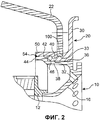
фиг.2 - увеличенный схематический вид детали, показанной на фиг.1;figure 2 is an enlarged schematic view of the part shown in figure 1;
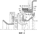
фиг.3 - схематический вид в разрезе половины системы крепления в соответствии со вторым способом осуществления предлагаемого изобретения;figure 3 is a schematic sectional view of half of a fastening system in accordance with a second embodiment of the invention;
фиг.4 - схематический вид в изометрии неподвижного конуса, установленного на дефлектор системы впрыскивания, показанной на фиг.3;4 is a schematic isometric view of a fixed cone mounted on the deflector of the injection system shown in FIG. 3;
фиг.5 - схематический вид в разрезе системы крепления в соответствии с третьим способом осуществления предлагаемого изобретения.5 is a schematic sectional view of a fastening system in accordance with a third embodiment of the present invention.
Как это можно видеть на фиг.1, система впрыскивания, обозначенная в целом общей позицией 2, состоит из неподвижной части, образованной кольцом 4, закручивающей частью 6, трубкой Вентури 8 и неподвижным конусом 10. Закручивающая часть 6 и неподвижный конус 10 соединяются друг с другом при помощи промежуточного кольца 12. Скользящий переход 14 установлен с возможностью скольжения на кольце 4. Закручивающая часть содержит две ступени лопаток, функция которых состоит в том, чтобы привести поток воздуха во вращательное движение относительно продольной оси YY системы впрыскивания. Неподвижный конус 10 содержит расширяющуюся форму 16, функция которой состоит в разделении потока смеси воздуха с топливом, выходящего из трубки Вентури 8.As can be seen in FIG. 1, the injection system, generally indicated by 2, consists of a fixed part formed by a ring 4, a twisting part 6, a
Дефлектор 20 установлен на донной части камеры сгорания 22. Донная часть камеры сгорания содержит две зоны закрепления 24 и 26. Зона закрепления 24 присоединена к стенке наружной камеры (не показана) и внутренняя зона закрепления 26 присоединена к стенке внутренней камеры, также не показанной на приведенных в приложении чертежах. Множество таких систем впрыскивания, количество которых обычно составляет от тринадцати до тридцати двух систем, равномерно отстоящих друг от друга в угловом измерении, устанавливаются на донную часть камеры сгорания 22 (на фиг.1 представлена только одна система впрыскивания).The
Дефлектор 20 содержит кольцевой диск 30 и кольцевую часть 32, припаянную к донной части камеры сгорания. Функция кольцевого диска 30 состоит в том, чтобы защитить зону донной части камеры сгорания, располагающуюся вокруг системы впрыскивания 2, от пламени из этой камеры сгорания. Кольцевая часть 32 вставлена в отверстие 33, выполненное в донной части камеры сгорания. Эта кольцевая часть содержит уступ 100, который упирается в заднюю по потоку стенку донной части камеры сгорания. Изнутри кольцевая часть 32 содержит расточку 36, в которой размещается цилиндрическая часть 38 неподвижного конуса 10. Кроме того, кольцевая часть 32 дефлектора содержит канавку удержания 40. Ребро 42 кольцевой части 32 дефлектора образует уступ удержания. Цилиндрическая часть 38 неподвижного конуса 10 продолжается фланцем 44 несколько большего диаметра, содержащим уступ удержания 46, ориентированный в направлении задней части турбореактивного двигателя и упирающийся в уступ удержания 42 дефлектора. Разрезное кольцо удержания 50 содержит круговой выступ 52, вставляющийся в канавку удержания 40 дефлектора 20. Сварные швы 54, например в количестве трех или четырех (см. фиг.2), обеспечивают соединение между фланцем 44 неподвижного конуса 10 и кольцом удержания 50.The
Установка системы впрыскивания на донную часть камеры сгорания осуществляется следующим образом. Прежде всего вставляют дефлектор 20 в отверстие 33, выполненное в донной части камеры сгорания, после чего устанавливают разрезное кольцо удержания 50 на дефлектор таким образом, чтобы круговой выступ 52 расположился внутри кольцевой канавки удержания 40 дефлектора. При этом две упомянутые детали соединяются между собой и с донной частью камеры сгорания 22 при помощи одной единственной операции пайки. После этого система впрыскивания устанавливается через переднюю часть турбореактивного двигателя, как это схематически показано стрелкой 56 на фиг.1, таким образом, чтобы цилиндрическая часть 38 неподвижного конуса установилась внутри расточки 36 дефлектора. В этом положении уступ 46, сформированный на части 44 неподвижного конуса, опирается на ребро 42 кольцевой части 32, образующее уступ удержания. Предпочтительно, чтобы передний конец части 44 располагался на том же уровне, что и передний конец разрезного кольца 50 так, чтобы была обеспечена возможность реализовать сварные швы 54 для соединения двух этих деталей.Installation of the injection system on the bottom of the combustion chamber is as follows. First of all, the
В этом варианте выполнения дефлектор 20 механически удерживается при помощи кругового выступа 52 разрезного кольца 50. Таким образом, даже допуская, что пайка, связывающая дефлектор с донной частью камеры сгорания 22, не выдержит воздействующей на нее нагрузки, дефлектор не будет затянут потоком газов в переднюю часть турбореактивного двигателя. С другой стороны, система впрыскивания 2 и, более конкретно, неподвижный конус 10, устанавливаются через переднюю часть турбореактивного двигателя, и они механически удерживаются при помощи вхождения в упор уступа 46 фланца 44 неподвижного конуса в уступ дефлектора 42. Таким образом, точки сварного соединения 54 не обеспечивают механическую прочность системы, но просто выполняют функцию предотвращения вращения системы впрыскивания 2 по отношению к разрезному кольцу 50.In this embodiment, the
В то же время облегчаются операции демонтажа системы впрыскивания, например, в том случае, когда требуется заменить дефектную систему впрыскивания. Действительно для этого достаточно удалить при помощи абразивного инструмента сварные швы 54, что позволяет освободить систему впрыскивания и обеспечивает возможность ее извлечения путем смещения системы в направлении, противоположном направлению, показанному на фиг.1 стрелкой 56. При этом паяные соединения дефлектора с донной частью камеры сгорания и разрезного кольца с дефлектором не затрагиваются. Аналогичным образом установка новой системы впрыскивания осуществляется очень просто, поскольку для этого достаточно вставить эту систему впрыскивания в расточку 36 и снова реализовать сварные швы 54. Таким образом, устройство дает многочисленные преимущества. Во-первых, оно позволяет исключить возможность попадания его деталей в камеру сгорания и в заднюю по потоку часть турбореактивного двигателя, в частности в турбину высокого давления. Во-вторых, устройство позволяет облегчить выполнение операций технического обслуживания, ремонта и замены дефектной системы впрыскивания.At the same time, the dismantling of the injection system is facilitated, for example, in the case where it is necessary to replace a defective injection system. Indeed, for this it is enough to remove the
На фиг.3 схематически представлен другой вариант реализации системы крепления, показанной на фиг.1 и 2.Figure 3 schematically shows another embodiment of the fastening system shown in figures 1 and 2.
Как уже было отмечено выше, в соответствии со способом выполнения, представленным на фиг.1 и 2, ни дефлектор, ни неподвижный конус системы впрыскивания не могут быть увлечены потоком газов в направлении задней части турбореактивного двигателя в случае разрушения паяных соединений, поскольку они удерживаются механически. Однако если механическое воздействие на систему впрыскивания осуществляется в противоположном направлении, то есть в направлении, противоположном тому, которое показано стрелкой 56 на фиг.1, усилие будет восприниматься сварными швами, которые при этом могут быть разрушены. Механическое воздействие такого типа может возникать в тот момент, когда инжекторы размещают в упомянутом скользящем переходе, поскольку там может иметь место заклинивание инжекторов. При этом усилия, воздействию которых подвергаются точки сварки в такой ситуации, могут в ряде случаев приводить к их разрушению. В этом случае упомянутый неподвижный конус будет отсоединен от донной части камеры сгорания 22. Эта ситуация будет представляться менее неблагоприятной, чем ситуация обратного порядка, в которой неподвижный конус может быть увлечен потоком газов в направлении задней части турбореактивного двигателя, поскольку система впрыскивания будет удерживаться при помощи инжекторов и давления. Однако для того, чтобы исключить этот недостаток, предусмотрен вариант выполнения, схематически представленный на фиг.3 и 4, в соответствии с которым система впрыскивания, и в частности неподвижный конус, составляющий неотъемлемую часть системы впрыскивания, удерживается механически в обоих направлениях без возникновения какого-либо усилия, воздействующего на упомянутые сварные швы.As already noted above, in accordance with the execution method shown in FIGS. 1 and 2, neither the deflector nor the fixed cone of the injection system can be entrained by the gas flow towards the rear of the turbojet in case of failure of the soldered joints, since they are mechanically held . However, if the mechanical action on the injection system is carried out in the opposite direction, that is, in the direction opposite to that shown by arrow 56 in figure 1, the force will be perceived by the welds, which in this case can be destroyed. A mechanical effect of this type can occur at the moment when the injectors are placed in the aforementioned sliding passage, since there may be a jamming of the injectors. At the same time, the efforts to which the welding points are exposed in such a situation can in some cases lead to their destruction. In this case, the said stationary cone will be disconnected from the bottom of the
В соответствии с этим вариантом выполнения используется идентичная форма дефлектора 20, но отличающаяся структура кольца удержания. Кольцо удержания 60 образовано внутренним кольцом 62 и кольцом запирания 64. Это внутреннее кольцо может быть выполнено разрезным, как в предыдущем варианте выполнения, или же оно может состоять из двух полуколец. Это кольцо удержания, как и в предыдущем случае, содержит круговой выступ 52, который размещается в канавке 40 дефлектора, и, кроме того, второй круговой выступ 66, который фиксирует в неподвижном положении фланец 44, располагающийся на конце цилиндрической части 38 неподвижного конуса. Таким образом, фланец 44 оказывается заблокированным по перемещению в двух направлениях. В направлении задней части турбореактивного двигателя этот фланец зафиксирован, как и в предыдущем случае, при помощи ребра 42 кольцевой части дефлектора 20. В другом направлении, то есть в направлении передней части турбореактивного двигателя, он зафиксирован при помощи второго кругового выступа 66 внутреннего кольца 62. Кольцо запирания 64 охватывает внутреннее кольцо 62 таким образом, чтобы не допустить расхождения разрезного кольца или двух упомянутых полуколец. Сварные швы 54 соединяют кольцо запирания 64 и внутреннее кольцо 62. Однако, в соответствии с этим вариантом выполнения, в отличие от предыдущего, сварные швы 54 не несут никакой механической нагрузки, поскольку блокирование по поступательному движению системы впрыскивания в обоих направлениях обеспечивается исключительно при помощи круговых выступов 52 и 66. Однако, как это можно видеть на фиг.4, необходимо предусмотреть средства, препятствующие вращательному движению. Действительно в варианте выполнения, представленном на фиг.1 и 2, функция воспрепятствования вращению обеспечивается при помощи самих точек сварки 54, чего уже не происходит в рассматриваемом варианте. Именно поэтому (см. фиг.4) в данном случае дефлектор содержит шип 70, имеющий, например, по существу, прямоугольное поперечное сечение, который предназначен для размещения в соответствующем вырезе 72 той же формы и того же сечения, выполненном на фланце 44 неподвижного конуса 10. Таким образом обеспечивают блокировку по вращательному движению упомянутого конуса по отношению к дефлектору, который сам в свою очередь закреплен при помощи пайки на стенке донной части камеры сгорания, как об этом уже было сказано выше.In accordance with this embodiment, an identical shape of the
На фиг.5 схематически представлен третий вариант осуществления изобретения, который сочетает в себе характеристики первого и второго вариантов, представленных соответственно на фиг.1 и 2, с одной стороны, и на фиг.3 и 4, с другой стороны. В соответствии с этим вариантом дефлектор 20 закреплен на донной части камеры сгорания 22 одновременно при помощи пайки и механическим образом, посредством паяного разрезного кольца 150, содержащего круговой выступ 152, который входит в круговую канавку 140, выполненную в кольцевой части 32 дефлектора 20. Этот вариант выполнения является подобным варианту выполнения, представленному на фиг.1 и 2. В то же время кольцевая часть дефлектора содержит вторую круговую канавку 158, предназначенную для размещения в ней одного из круговых выступов кольца удержания 160. Как об этом уже было сказано выше со ссылками на фиг.3 и 4, кольцо удержания образовано внутренним кольцом 162 и кольцом запирания 164, которое охватывает это внутреннее кольцо 162.Figure 5 schematically shows a third embodiment of the invention, which combines the characteristics of the first and second variants, presented in figures 1 and 2, respectively, on the one hand, and in figures 3 and 4, on the other hand. According to this embodiment, the
Как и в предшествующих случаях, внутреннее кольцо 162 может представлять собой разрезное кольцо или может быть образовано двумя полукольцами. Это внутреннее кольцо содержит первый круговой выступ 166 и второй круговой выступ 168. Внутреннее кольцо имеет конические опорные поверхности, позволяющие устранить осевые зазоры. Осевые усилия, которые стремятся раскрыть разрезное кольцо или два полукольца, воспринимаются кольцом запирания 164. Сварные швы 154 обеспечивают связь между внутренним кольцом 162 и кольцом запирания 164. Эти сварные швы в данном случае не подвергаются механическому воздействию.As in the previous cases, the
Устройство в соответствии с этим вариантом выполнения функционирует также и в том случае, когда упомянутые опорные поверхности не являются коническими. При этом существует небольшой осевой зазор, связанный с допусками изготовления.The device in accordance with this embodiment also functions when said supporting surfaces are not conical. However, there is a small axial clearance associated with manufacturing tolerances.
Claims (13)
Applications Claiming Priority (4)
| Application Number | Priority Date | Filing Date | Title |
|---|---|---|---|
| FR0551518 | 2005-06-07 | ||
| FR0551518A FR2886714B1 (en) | 2005-06-07 | 2005-06-07 | ANTI-ROTARY INJECTION SYSTEM FOR TURBO-REACTOR |
| FR0552929 | 2005-09-28 | ||
| FR0552929A FR2886715B1 (en) | 2005-06-07 | 2005-09-28 | SYSTEM FOR FASTENING AN INJECTION SYSTEM ON A TURBOREACTOR COMBUSTION CHAMBER BOTTOM AND METHOD OF FASTENING |
Publications (2)
| Publication Number | Publication Date |
|---|---|
| RU2006119912A RU2006119912A (en) | 2007-12-20 |
| RU2406935C2 true RU2406935C2 (en) | 2010-12-20 |
Family
ID=36972884
Family Applications (1)
| Application Number | Title | Priority Date | Filing Date |
|---|---|---|---|
| RU2006119912/06A RU2406935C2 (en) | 2005-06-07 | 2006-06-06 | Fixing device of spraying system on bottom part of combustion chamber of jet-turbine engine and method of such fixation |
Country Status (5)
| Country | Link |
|---|---|
| US (1) | US7673460B2 (en) |
| EP (1) | EP1731839B1 (en) |
| JP (1) | JP4875928B2 (en) |
| CA (1) | CA2548869C (en) |
| RU (1) | RU2406935C2 (en) |
Cited By (1)
| Publication number | Priority date | Publication date | Assignee | Title |
|---|---|---|---|---|
| RU2583486C2 (en) * | 2011-01-31 | 2016-05-10 | Снекма | Injector for turbomachine combustion chamber |
Families Citing this family (26)
| Publication number | Priority date | Publication date | Assignee | Title |
|---|---|---|---|---|
| US7628019B2 (en) * | 2005-03-21 | 2009-12-08 | United Technologies Corporation | Fuel injector bearing plate assembly and swirler assembly |
| FR2893390B1 (en) * | 2005-11-15 | 2011-04-01 | Snecma | BOTTOM OF COMBUSTION CHAMBER WITH VENTILATION |
| FR2897923B1 (en) * | 2006-02-27 | 2008-06-06 | Snecma Sa | ANNULAR COMBUSTION CHAMBER WITH REMOVABLE BACKGROUND |
| FR2903169B1 (en) * | 2006-06-29 | 2011-11-11 | Snecma | DEVICE FOR INJECTING A MIXTURE OF AIR AND FUEL, COMBUSTION CHAMBER AND TURBOMACHINE HAVING SUCH A DEVICE |
| FR2910115B1 (en) * | 2006-12-19 | 2012-11-16 | Snecma | DEFLECTOR FOR BOTTOM OF COMBUSTION CHAMBER, COMBUSTION CHAMBER WHERE IT IS EQUIPPED AND TURBOREACTOR COMPRISING THEM |
| FR2918443B1 (en) * | 2007-07-04 | 2009-10-30 | Snecma Sa | COMBUSTION CHAMBER COMPRISING THERMAL PROTECTION DEFLECTORS OF BOTTOM BOTTOM AND GAS TURBINE ENGINE BEING EQUIPPED |
| FR2921462B1 (en) * | 2007-09-21 | 2012-08-24 | Snecma | ANNULAR COMBUSTION CHAMBER FOR A GAS TURBINE ENGINE |
| FR2921464B1 (en) * | 2007-09-24 | 2014-03-28 | Snecma | ARRANGEMENT OF INJECTION SYSTEMS IN A COMBUSTION CHAMBER BOTTOM OF AN AIRCRAFT ENGINE |
| DE102007050276A1 (en) * | 2007-10-18 | 2009-04-23 | Rolls-Royce Deutschland Ltd & Co Kg | Lean premix burner for a gas turbine engine |
| FR2929690B1 (en) * | 2008-04-03 | 2012-08-17 | Snecma Propulsion Solide | COMBUSTION CHAMBER SECTORIZED IN CMC FOR GAS TURBINE |
| FR2932251B1 (en) * | 2008-06-10 | 2011-09-16 | Snecma | COMBUSTION CHAMBER FOR A GAS TURBINE ENGINE COMPRISING CMC DEFLECTORS |
| US8327648B2 (en) * | 2008-12-09 | 2012-12-11 | Pratt & Whitney Canada Corp. | Combustor liner with integrated anti-rotation and removal feature |
| US9127842B2 (en) * | 2009-05-27 | 2015-09-08 | Siemens Aktiengesellschaft | Burner, operating method and assembly method |
| JP4815513B2 (en) * | 2009-07-06 | 2011-11-16 | 川崎重工業株式会社 | Gas turbine combustor |
| FR2963061B1 (en) * | 2010-07-26 | 2012-07-27 | Snecma | FUEL INJECTION SYSTEM FOR TURBO-REACTOR AND METHOD FOR ASSEMBLING SUCH AN INJECTION SYSTEM |
| FR2964177B1 (en) | 2010-08-27 | 2012-08-24 | Snecma | AIRCRAFT ENGINE COMBUSTION CHAMBER AND METHOD OF FIXING AN INJECTION SYSTEM IN AN AIRCRAFT ENGINE COMBUSTION CHAMBER |
| GB201107095D0 (en) * | 2011-04-28 | 2011-06-08 | Rolls Royce Plc | A head part of an annular combustion chamber |
| FR2986856B1 (en) | 2012-02-15 | 2018-05-04 | Safran Aircraft Engines | DEVICE FOR INJECTING AIR AND FUEL FOR A COMBUSTION CHAMBER OF A TURBOMACHINE |
| US9021812B2 (en) * | 2012-07-27 | 2015-05-05 | Honeywell International Inc. | Combustor dome and heat-shield assembly |
| FR3026827B1 (en) * | 2014-10-01 | 2019-06-07 | Safran Aircraft Engines | TURBOMACHINE COMBUSTION CHAMBER |
| GB2543803B (en) * | 2015-10-29 | 2019-10-30 | Rolls Royce Plc | A combustion chamber assembly |
| US10473332B2 (en) | 2016-02-25 | 2019-11-12 | General Electric Company | Combustor assembly |
| DE102017217328A1 (en) * | 2017-09-28 | 2019-03-28 | Rolls-Royce Deutschland Ltd & Co Kg | Axial extension nozzle for a combustion chamber of an engine |
| US11280492B2 (en) * | 2018-08-23 | 2022-03-22 | General Electric Company | Combustor assembly for a turbo machine |
| US11466858B2 (en) * | 2019-10-11 | 2022-10-11 | Rolls-Royce Corporation | Combustor for a gas turbine engine with ceramic matrix composite sealing element |
| FR3103540B1 (en) * | 2019-11-26 | 2022-01-28 | Safran Aircraft Engines | Fuel injection system of a turbomachine, combustion chamber comprising such a system and associated turbomachine |
Family Cites Families (10)
| Publication number | Priority date | Publication date | Assignee | Title |
|---|---|---|---|---|
| US4216652A (en) | 1978-06-08 | 1980-08-12 | General Motors Corporation | Integrated, replaceable combustor swirler and fuel injector |
| DE3564024D1 (en) * | 1984-02-29 | 1988-09-01 | Lucas Ind Plc | Combustion equipment |
| FR2572463B1 (en) * | 1984-10-30 | 1989-01-20 | Snecma | INJECTION SYSTEM WITH VARIABLE GEOMETRY. |
| US5117637A (en) * | 1990-08-02 | 1992-06-02 | General Electric Company | Combustor dome assembly |
| JPH04116316A (en) * | 1990-09-05 | 1992-04-16 | Jisedai Koukuuki Kiban Gijutsu Kenkyusho:Kk | Swirler of combustion apparatus |
| US6212870B1 (en) | 1998-09-22 | 2001-04-10 | General Electric Company | Self fixturing combustor dome assembly |
| US6502400B1 (en) | 2000-05-20 | 2003-01-07 | General Electric Company | Combustor dome assembly and method of assembling the same |
| US6442940B1 (en) * | 2001-04-27 | 2002-09-03 | General Electric Company | Gas-turbine air-swirler attached to dome and combustor in single brazing operation |
| US6782620B2 (en) * | 2003-01-28 | 2004-08-31 | General Electric Company | Methods for replacing a portion of a combustor dome assembly |
| FR2859272B1 (en) * | 2003-09-02 | 2005-10-14 | Snecma Moteurs | AIR / FUEL INJECTION SYSTEM IN A TURBOMACHINE COMBUSTION CHAMBER HAVING MEANS FOR GENERATING COLD PLASMA |
-
2006
- 2006-06-05 US US11/422,177 patent/US7673460B2/en active Active
- 2006-06-06 JP JP2006156882A patent/JP4875928B2/en active Active
- 2006-06-06 CA CA2548869A patent/CA2548869C/en active Active
- 2006-06-06 EP EP06115000.9A patent/EP1731839B1/en active Active
- 2006-06-06 RU RU2006119912/06A patent/RU2406935C2/en active
Cited By (1)
| Publication number | Priority date | Publication date | Assignee | Title |
|---|---|---|---|---|
| RU2583486C2 (en) * | 2011-01-31 | 2016-05-10 | Снекма | Injector for turbomachine combustion chamber |
Also Published As
| Publication number | Publication date |
|---|---|
| JP2006343092A (en) | 2006-12-21 |
| EP1731839A2 (en) | 2006-12-13 |
| US7673460B2 (en) | 2010-03-09 |
| JP4875928B2 (en) | 2012-02-15 |
| EP1731839B1 (en) | 2015-08-05 |
| CA2548869C (en) | 2014-05-20 |
| EP1731839A3 (en) | 2013-05-08 |
| CA2548869A1 (en) | 2006-12-07 |
| RU2006119912A (en) | 2007-12-20 |
| US20070084215A1 (en) | 2007-04-19 |
Similar Documents
| Publication | Publication Date | Title |
|---|---|---|
| RU2406935C2 (en) | Fixing device of spraying system on bottom part of combustion chamber of jet-turbine engine and method of such fixation | |
| RU2490547C2 (en) | Guide device of element in hole of combustion chamber wall of gas-turbine engine, combustion chamber and gas-turbine engine | |
| CA2578565C (en) | Method and apparatus for gas turbine engines | |
| US6581386B2 (en) | Threaded combustor baffle | |
| JP2006266669A (en) | Bearing plate assembly, swirler assembly, and bearing plate, swivel ball and nozzle tip bushing for fuel injector assembly | |
| RU2435105C2 (en) | Design of combustion chamber for gas turbine engine, which has deflector with projecting edge, combustion chamber of gas turbine engine, which contains above mentioned design, and gas turbine engine | |
| JP6461129B2 (en) | Combustor device in a gas turbine engine | |
| CA2635171C (en) | Pre-loaded internal fuel manifold support | |
| US20110088409A1 (en) | Fuel injector mounting system | |
| EP1593913B1 (en) | Gas turbine annular combustion chamber with improved inner support flange | |
| JP5149596B2 (en) | Combustor dome mixer holding means | |
| EP3348814B1 (en) | Seal member assembly structure and assembly method, seal member, and gas turbine | |
| US8033113B2 (en) | Fuel injection system for a gas turbine engine | |
| JPH10510911A (en) | Fuel nozzle guide holding assembly | |
| US7318704B2 (en) | Gas turbine engine structure | |
| US20140137536A1 (en) | Super telescoping cross-fire tube and method of assembling a combustor structure | |
| US20100064690A1 (en) | Fuel nozzle tip assembly | |
| JP2001201048A (en) | Swirler assembly for combustor | |
| US8726669B2 (en) | Combustor dome with combined deflector/mixer retainer | |
| EP3499128A1 (en) | Fuel injector systems and support structures | |
| US20190249605A1 (en) | Aircraft engine seal carrier including anti-rotation feature | |
| CN110542119A (en) | Combustion module for a gas turbine engine with a combustion chamber bottom stop | |
| US20080053096A1 (en) | Fuel injection system and method of assembly | |
| US10641493B2 (en) | Aerodynamic fastening of turbomachine fuel injectors | |
| JP2014001920A (en) | Cross-fire tube holding system for gas-turbine engine |
Legal Events
| Date | Code | Title | Description |
|---|---|---|---|
| PD4A | Correction of name of patent owner |