RU2404309C1 - Linen processing machine - Google Patents
Linen processing machine Download PDFInfo
- Publication number
- RU2404309C1 RU2404309C1 RU2009116550/21A RU2009116550A RU2404309C1 RU 2404309 C1 RU2404309 C1 RU 2404309C1 RU 2009116550/21 A RU2009116550/21 A RU 2009116550/21A RU 2009116550 A RU2009116550 A RU 2009116550A RU 2404309 C1 RU2404309 C1 RU 2404309C1
- Authority
- RU
- Russia
- Prior art keywords
- casing
- air
- compartment
- partition
- water
- Prior art date
Links
Images


Classifications
-
- D—TEXTILES; PAPER
- D06—TREATMENT OF TEXTILES OR THE LIKE; LAUNDERING; FLEXIBLE MATERIALS NOT OTHERWISE PROVIDED FOR
- D06F—LAUNDERING, DRYING, IRONING, PRESSING OR FOLDING TEXTILE ARTICLES
- D06F31/00—Washing installations comprising an assembly of several washing machines or washing units, e.g. continuous flow assemblies
-
- D—TEXTILES; PAPER
- D06—TREATMENT OF TEXTILES OR THE LIKE; LAUNDERING; FLEXIBLE MATERIALS NOT OTHERWISE PROVIDED FOR
- D06F—LAUNDERING, DRYING, IRONING, PRESSING OR FOLDING TEXTILE ARTICLES
- D06F29/00—Combinations of a washing machine with other separate apparatus in a common frame or the like, e.g. with rinsing apparatus
- D06F29/005—Combinations of a washing machine with other separate apparatus in a common frame or the like, e.g. with rinsing apparatus the other separate apparatus being a drying appliance
Landscapes
- Engineering & Computer Science (AREA)
- Textile Engineering (AREA)
- Detail Structures Of Washing Machines And Dryers (AREA)
- Accessory Of Washing/Drying Machine, Commercial Washing/Drying Machine, Other Washing/Drying Machine (AREA)
- Main Body Construction Of Washing Machines And Laundry Dryers (AREA)
Abstract
Description
Настоящее изобретение относится к машине для обработки белья.The present invention relates to a machine for processing linen.
Обычно машины для обработки белья являются бытовыми устройствами, которые используются для чистки белья посредством стирки белья с использованием моющего средства и механического трения и сушки. Стиральные машины подразделяются на стиральные машины, сушильные машины и единые устройства, выполняющие функции как стирки, так и сушки.Typically, laundry machines are household appliances that are used to clean laundry by washing laundry using detergent and mechanical friction and drying. Washing machines are divided into washing machines, dryers and single devices that perform the functions of both washing and drying.
Настоящее изобретение относится к машине для обработки белья.The present invention relates to a machine for processing linen.
Целью настоящего изобретения является создание машины для обработки белья с повышенной эффективностью обработки белья, которая имеет улучшенный общий внешний вид.The aim of the present invention is to provide a machine for processing sheets with increased efficiency of processing sheets, which has an improved overall appearance.
Дополнительные преимущества, цели и признаки раскрытия будут изложены частично в нижеследующем описании и частично станут понятными для специалистов в данной области техники при изучении нижеследующего или практическом использовании настоящего изобретения. Цели и другие преимущества настоящего изобретения могут быть осуществлены и достигнуты при помощи конструкции, раскрытой в его описании и формуле изобретения, а также на прилагаемых чертежах.Additional advantages, objects, and features of the disclosure will be set forth in part in the description which follows and in part will become apparent to those skilled in the art upon study of the following or practical use of the present invention. The objectives and other advantages of the present invention can be realized and achieved using the design disclosed in its description and claims, as well as in the accompanying drawings.
Для достижения этих целей и других преимуществ, а также в соответствии с целью настоящего изобретения, как осуществлено и широко описано в данном документе, машина для обработки белья содержит корпус, перегородку, разделяющую внутреннее отделение корпуса на первое отделение для основной стирки белья, и второе отделение для дополнительной стирки белья, устройство для подачи воздуха, расположенное на нижней поверхности первого отделения, причем устройство для подачи воздуха селективно нагревает воздух внутри корпуса и подает воздух вниз во второе отделение, при этом устройство для подачи воздуха содержит единый кожух, вентилятор и нагревательное устройство, причем вентилятор и нагревательное устройство расположены в кожухе.To achieve these goals and other advantages, as well as in accordance with the purpose of the present invention, as implemented and widely described herein, the laundry machine comprises a housing, a partition separating the interior of the housing into a first laundry main compartment, and a second compartment for additional washing of laundry, an air supply device located on the lower surface of the first compartment, wherein the air supply device selectively heats the air inside the housing and delivers air down in the second compartment, while the device for supplying air contains a single casing, a fan and a heating device, and the fan and heating device are located in the casing.
Одиночная разделительная стенка может образовывать основание первого отделения, и верхнюю крышку второго отделения.A single dividing wall may form the base of the first compartment, and the top cover of the second compartment.
Машина для обработки белья может дополнительно содержать устройство для подачи воздуха во второе отделение.The laundry machine may further comprise a device for supplying air to the second compartment.
Устройство для подачи воздуха может содержать устройство для предотвращения прохождения воды в кожух.The air supply device may include a device to prevent the passage of water into the casing.
Кожух может включать в себя нижний кожух, установленный с возможностью съема в корпусе, и верхний кожух, соединенный с возможностью съема с нижним кожухом. Устройство для предотвращения прохождения воды может включать в себя первую выступающую часть, проходящую вниз от кромки верхнего кожуха, для закрытия заданной части кожуха, и вторую выступающую часть, проходящую вверх от кромки нижнего кожуха для соединения с первой выступающей частью путем введения в нее.The casing may include a lower casing removably mounted in the housing and an upper casing removably connected to the lower casing. The device for preventing the passage of water may include a first protruding portion extending downward from the edge of the upper casing to close a predetermined portion of the casing, and a second protruding portion extending upward from the edge of the lower casing for connection with the first protruding portion by insertion therein.
Кожух может дополнительно содержать сквозное отверстие, соединяющее внутреннюю сторону с наружной стороной кожуха, для прохождения провода через него, и устройство для предотвращения прохождения воды может включать в себя устройство для предотвращения проникновения воды через сквозное отверстие.The casing may further comprise a through hole connecting the inner side to the outer side of the casing for the wire to pass through it, and the device for preventing the passage of water may include a device for preventing water from entering through the through hole.
Устройство для подачи воздуха может содержать электродвигатель, расположенный под кожухом, причем электродвигатель вращает вентилятор, и устройство для предотвращения доступа воды в часть под кожухом, где расположен электродвигатель.The device for supplying air may include an electric motor located under the casing, and the electric motor rotates the fan, and a device for preventing water from entering the part under the casing where the electric motor is located.
Устройство для предотвращения доступа воды может содержать опорную часть, проходящую вниз от нижней части кожуха, причем устройство для предотвращения доступа воды предотвращает покрытие наружной нижней поверхности кожуха.The device for preventing access of water may contain a support portion extending downward from the lower part of the casing, and the device for preventing access of water prevents coating the outer lower surface of the casing.
Устройство для предотвращения доступа воды может включать в себя выступающую часть, расположенную в кожухе, причем выступающая часть предотвращает доступ воды в часть под кожухом, где расположен электродвигатель.The device for preventing access of water may include a protruding part located in the casing, and the protruding part prevents access of water to the part under the casing where the electric motor is located.
Впуск через который воздух всасывается в устройство для подачи воздуха, может быть образован на нижней поверхности кожуха.An inlet through which air is sucked into the air supply device may be formed on the lower surface of the casing.
Установочная часть может быть выполнена как одно целое с нижней поверхностью кожуха.The installation part can be made integrally with the lower surface of the casing.
По меньшей мере, один крепежный круглый выступ, выполненный на установочной части, может прикрепляться к устройству управления, и, по меньшей мере, один крепежный круглый выступ может точно определять положение устройства управления.At least one fixing round protrusion made on the mounting part can be attached to the control device, and at least one fixing round protrusion can accurately determine the position of the control device.
Внутреннее отделение корпуса может быть разделено на первое отделение и второе отделение с помощью одной перегородки. В данном документе устройство для подачи воздуха может прикрепляться к перегородке посредством скольжения по верхней поверхности перегородки.The inner compartment of the housing can be divided into the first compartment and the second compartment using a single partition. In this document, the air supply device may be attached to the partition by sliding over the upper surface of the partition.
Устройство для подачи воздуха может содержать, по меньшей мере, один круглый выступ, соединенный с перегородкой с помощью крепежного элемента.The air supply device may include at least one round protrusion connected to the partition by means of a fastener.
Крепежная часть может быть расположена на верхней поверхности перегородки и может выступать в соответствии с круглым выступом.The fastening part may be located on the upper surface of the partition and may protrude in accordance with a round protrusion.
Круглый выступ может выступать вверх от перегородки, и толщина круглого выступа и крепежная часть могут соответствовать длине корпуса крепежного элемента, прикрепленного к круглому выступу.The round protrusion may protrude upward from the partition, and the thickness of the round protrusion and the fastening part may correspond to the length of the housing of the fastener attached to the round protrusion.
Необходимо понимать, что как вышеизложенное общее описание, так и нижеследующее подробное описание настоящего изобретения являются иллюстративными и поясняющими и предназначены для обеспечения дополнительного объяснения настоящего изобретения, как заявлено.It should be understood that both the foregoing general description and the following detailed description of the present invention are illustrative and explanatory and are intended to provide an additional explanation of the present invention as claimed.
Сопроводительные чертежи, которые включены для обеспечения дальнейшего понимания раскрытия и составляют часть данной заявки, иллюстрируют вариант осуществления (варианты осуществления) данного раскрытия и вместе с описанием служат для объяснения принципа раскрытия.The accompanying drawings, which are included to provide a further understanding of the disclosure and form part of this application, illustrate an embodiment (embodiments) of the disclosure and, together with the description, serve to explain the disclosure principle.
На чертежах:In the drawings:
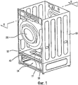
фиг.1 - перспективный вид, иллюстрирующий машину для обработки белья в соответствии с примером варианта осуществления;1 is a perspective view illustrating a laundry machine in accordance with an example embodiment;
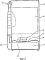
фиг.2 - вид в разрезе по линии II-II на фиг.1;figure 2 is a view in section along the line II-II in figure 1;
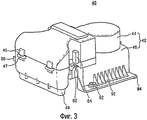
фиг.3 - перспективный вид, иллюстрирующий устройство для подачи воздуха с фиг.1;figure 3 is a perspective view illustrating a device for supplying air from figure 1;
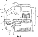
фиг.4 - перспективный вид, иллюстрирующий верхний кожух с фиг.3, который отсоединен;figure 4 is a perspective view illustrating the upper casing of figure 3, which is disconnected;
фиг.5 - перспективный вид, иллюстрирующий заднюю поверхность устройства для подачи воздуха с фиг.3;5 is a perspective view illustrating a rear surface of the air supply device of FIG. 3;
фиг.6 - вид в разрезе сбоку, иллюстрирующий круглый выступ устройства для подачи воздуха с фиг.3;6 is a side sectional view illustrating a round protrusion of the air supply device of FIG. 3;
фиг.7 - вид в разрезе сбоку, иллюстрирующий соединение между верхним кожухом и нижним кожухом;7 is a sectional side view illustrating the connection between the upper casing and the lower casing;
фиг.8 - вид, схематически иллюстрирующий поток воздуха внутри выдвижного ящика;Fig. 8 is a view schematically illustrating air flow inside a drawer;
фиг.9 - перспективный вид, иллюстрирующий положение установленного датчика температуры с фиг.3;Fig.9 is a perspective view illustrating the position of the installed temperature sensor of Fig.3;
фиг.10 - вид сверху, иллюстрирующий вариант осуществления фиксирующего элемента с фиг.3;figure 10 is a top view illustrating an embodiment of the locking element of figure 3;
фиг.11 - перспективный вид, иллюстрирующий другой вариант осуществления фиксирующего элемента с фиг.3;11 is a perspective view illustrating another embodiment of a locking element of FIG. 3;
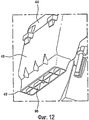
фиг.12 - перспективный вид, иллюстрирующий воздуховыпускное отверстие с фиг.3;Fig. 12 is a perspective view illustrating the air outlet of Fig. 3;
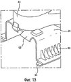
фиг.13 - перспективный вид, иллюстрирующий заднюю поверхность устройства для подачи воздуха, показанную сверху;13 is a perspective view illustrating a rear surface of an air supply device shown above;
фиг.14 - перспективный вид, иллюстрирующий устройство для подачи воздуха, показанное снизу;Fig. 14 is a perspective view illustrating an air supply device shown from below;
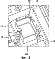
фиг.15 - перспективный вид, иллюстрирующий направляющее устройство, в котором расположено устройство управления;15 is a perspective view illustrating a guiding device in which a control device is located;
фиг.16 - перспективный вид, иллюстрирующий устройство для подачи воздуха, показанное снизу; иFig. 16 is a perspective view illustrating an air supply device shown from below; and
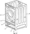
фиг.17 - перспективный вид, иллюстрирующий машину для обработки белья в соответствии с примером варианта осуществления настоящего изобретения.17 is a perspective view illustrating a laundry machine in accordance with an example embodiment of the present invention.
Подробно будет сделана ссылка на конкретные варианты осуществления настоящего изобретения, примеры которых проиллюстрированы на сопроводительных чертежах. Там, где возможно, подобные ссылочные позиции будут использоваться на чертежах для обозначения одинаковых или подобных элементов.Reference will be made in detail to specific embodiments of the present invention, examples of which are illustrated in the accompanying drawings. Where possible, similar reference numerals will be used throughout the drawings to refer to the same or like elements.
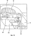
Как показано на фиг.1 и 3, машина для обработки белья содержит корпус 10 и перегородку 16. Перегородка 16 разделяет внутреннее отделение на, по меньшей мере, два отделения. Перегородка 16 может быть одиночной перегородкой, которая будет описана подробно ниже. Одиночная перегородка 16 может разделять внутреннее отделение корпуса 10 на первое отделение или основное отделение 12, и второе отделение или вспомогательное отделение 14. Основная обработка белья может выполняться в первом отделении или основном отделении 12. Первое отделение 12 для обработки белья может содержать устройство для стирки белья или устройство для сушки белья. Дополнительная обработка белья может выполняться во втором отделении или дополнительном отделении 14. Переключатель 13 расположен на корпусе 10, который позволяет пользователю выбирать желаемые операции для белья.As shown in figures 1 and 3, the machine for processing linen includes a
В данном документе указанная основная обработка белья может означать известные операции стирки и/или сушки, и дополнительная обработка белья может означать дополнительные операции стирки, сушки или освежения белья, или может означать операции сушки или освежения белья небольшого размера. Термин «освежение» может означать процесс удаления морщинок, уничтожения запаха, санитарную обработку, снятия статического электричества или нагревания белья посредством подачи воздуха, нагретого воздуха, пара, воды на белье. Термин «белье» может означать не только одежду, но также все виды носимых предметов одежды, таких как обувь, носки, перчатки и головные уборы. Таким образом, белье означает все виды белья, для которых могут выполняться операции обработки белья.In this document, said main laundry treatment may mean known washing and / or drying operations, and additional laundry processing may mean additional washing, drying or refreshing operations of the laundry, or may mean drying or refreshing operations of small laundry. The term “refreshment” may mean the process of removing wrinkles, eliminating odors, sanitizing, removing static electricity or heating the laundry by supplying air, heated air, steam, water to the laundry. The term “underwear” can mean not only clothes, but also all kinds of wearable garments, such as shoes, socks, gloves and hats. Thus, laundry means all types of laundry for which laundry processing operations can be performed.
Корпус 10 определяет внешний вид машины для обработки белья. В корпусе 10 могут быть установлены различные элементы. Вращающийся барабан 20 может быть установлен в первом отделении 12 в корпусе 10, и съемный выдвижной ящик 30 может быть установлен во втором отделении 14. Барабан 20 и выдвижной ящик 30 выполнены с возможностью вмещения белья. Если машина для обработки белья выполнена в качестве стиральной машины или отдельного устройства, имеющего функции как стирки, так и сушки, дополнительно может быть установлен бак (не показан) для вмещения воды для стирки, и барабан 20 может быть установлен в баке.The
Корпус 10 может быть образован из двух отдельных элементов, которые включают в себя первое отделение 12 и второе отделение 14. Более конкретно, корпус 10 может содержать пару первых боковых стенок на противоположных сторонах первого отделения 12 для обработки белья и пару вторых боковых стенок на противоположных сторонах второго отделения 14 для обработки белья, причем пара первых боковых стенок примыкает к паре вторых боковых стенок. В качестве альтернативы, корпус 10 может быть образован из одного элемента. В одном варианте осуществления первое отделение 12 и второе отделение 14 образованы в корпусе 10, выполненном из одного элемента. Более конкретно, корпус 10 может включать в себя первую боковую стенку и вторую боковую стенку, причем каждая из первой и второй боковых стенок проходит непрерывно и не прерывается от первого отделения 12 для обработки белья до второго отделения 14 для обработки белья, как показано, например, на фиг.17. Если первое отделение 12 и второе отделение 14 образованы в корпусе 10, выполненном из одного элемента, сборка корпуса 10 будет простой, и, соответственно, время, необходимое для сборки, будет уменьшено.The
В соответствии со стиральной машиной данного варианта осуществления корпус 10, выполненный из одного элемента, включает в себя первое отделение 12 и второе отделение 14, и он дополнительно включает в себя перегородку 16, которая разделяет внутреннее отделение корпуса 10 на первое отделение 12 и второе отделение 14. Перегородка 16 может быть реализована в виде стенки, расположенной внутри корпуса 10, которая проходит между первой боковой стенкой и второй боковой стенкой. Перегородка 16 делит внутреннее отделение по горизонтали на верхнее отделение, соответствующее первому отделению 12, и нижнее отделение, соответствующее второму отделению 14. Однако настоящее изобретение не ограничивается указанным.According to the washing machine of this embodiment, the
То есть в соответствии с данным вариантом осуществления, корпус 10 включает в себя перегородку 16, которая одновременно используется в качестве основания первого отделения 12 и в качестве верхней крышки второго отделения 14. Более конкретно, перегородка 16 имеет первую сторону и вторую сторону, причем первая сторона открыта в первое отделение 12 для обработки белья, и вторая сторона открыта во второе отделение 14 для обработки белья.That is, in accordance with this embodiment, the
Так как одиночная перегородка 16 используется в качестве основания первого отделения 12 и в качестве верхней крышки второго отделения 14, сборка будет очень простой, и, соответственно, время, необходимое для сборки, будет уменьшено по сравнению со случаем, включающим в себя отдельное основание первого отделения 12 и отдельную верхнюю крышку второго отделения 14. Наличие одиночной перегородки 16 по сравнению с отдельной перегородкой для каждого из первого и второго отделений 12, 14, обеспечивает простую конструкцию машины для обработки белья в целом, и обеспечивает приятный внешний вид машины для обработки белья. Кроме того, использование одиночной перегородки 16 упрощает сборку и уменьшает затраты вследствие уменьшения необходимого материала по сравнению с использованием отдельных перегородок. В конечном счете одиночная перегородка 16 обеспечивает эффективное использование первого и второго отделений 12, 14 и легкий доступ в первое отделение 12.Since a
Кроме того, машина для обработки белья может дополнительно включать в себя устройство 40 для подачи воздуха для подачи воздуха или нагретого воздуха во второе отделение 14.In addition, the laundry machine may further include an
Устройство 40 для подачи воздуха может быть расположено в первом отделении 12, и предусматривается, что устройство для подачи воздуха располагается на верхней поверхности перегородки 16. Перегородка 16 включает в себя отверстие 15, так что воздух подается через перегородку 16 и во второе отделение 14 для обработки белья. Устройство 40 для подачи воздуха включает в себя воздуховыпускное отверстие 49 (см. фиг.12), которое может непосредственно соединяться с отверстием 15 в перегородке 16. Отверстие 15 расположено в центральной части перегородки.An
Барабан 20, предназначенный для вращения, может быть установлен в первом отделении 12, и выдвижной ящик 10 может быть установлен во втором отделении 14. Объем первого отделения 12 может, по существу, быть больше объема второго отделения 14. В результате, для эффективного использования внутреннего отделения, предусматривается, что устройство 40 для подачи воздуха располагается в первом отделении 12, а не во втором отделении 14. Такое расположение позволяет максимизировать величину внутреннего объема второго отделения 14, пригодного для вмещения белья. Кроме того, расположение устройства 40 для подачи воздуха на наружной стороне второго отделения 14 упрощает конструкцию второго отделения 14 и обеспечивает больше свободы исполнения второго отделения 14. В конечном счете, так как внутренняя часть второго отделения 14 является легкодоступной для пользователя через выдвижной ящик 30, размещение устройства 40 для подачи воздуха на площади, отличной от второго отделения 14, обеспечивает дополнительную степень безопасности для пользователя.A
Расположение устройства 40 для подачи воздуха в первом отделении 12 для обработки белья с подачей воздуха через отверстие 15 в перегородке 16 обеспечивает в основном направленный вниз воздушный поток во второе отделение 14 для обработки белья. Этот направленный вниз воздушный поток особенно полезен для сушки или обработки ботинок 100, так как воздух подается вниз на верх ботинка 100 для охватывания верха ботинка 100 воздушным потоком по сравнению с горизонтальным воздушным потоком, который может только направляться на одну сторону ботинка, или направленным вверх воздушным потоком, который будет задерживаться подошвой ботинка.The arrangement of the
Кроме того, направленный вниз воздушный поток перемещается в нижнюю часть выдвижного ящика и, затем, будет стремиться распространяться во всех направлениях, обеспечивая полностью распределенный воздушный поток и уменьшая возможные мертвые зоны с небольшим воздушным потоком или без него в выдвижном ящике 30.In addition, the downward-directed airflow moves to the bottom of the drawer and, then, will tend to spread in all directions, providing a fully distributed airflow and reducing possible dead zones with little or no airflow in the
Более конкретно, выдвижной ящик 30 включает в себя нижнюю стенку и множество боковых стенок, которые образуют закрытое отделение с открытой верхней стороной. Высота боковых стенок может быть меньше ширины и глубины выдвижного ящика 30, так что выпускное отверстие воздушного потока из устройства 40 для подачи воздуха расположено относительно близко к нижней части выдвижного ящика, так что нижняя часть выдвижного ящика стремится переориентировать направленный вниз воздушный поток на наружную сторону во всех направлениях.More specifically, the
Нижняя часть выдвижного ящика и множество боковых стенок могут быть выполнены с возможностью предотвращения прохождения воздуха через них, чтобы максимизировать количество воздуха, который переориентируется вверх. Однако предусматривается, чтобы нижняя часть выдвижного ящика и/или боковые стенки выдвижного ящика могли содержать одно или более отверстий, таких как ряд небольших вентиляционных отверстий, сетка или сетчатый фильтр, для обеспечения прохождения некоторой части воздушного потока через них.The lower part of the drawer and the plurality of side walls can be configured to prevent air from passing through them to maximize the amount of air that is reoriented upward. However, it is contemplated that the bottom of the drawer and / or the side walls of the drawer may contain one or more openings, such as a series of small ventilation openings, a mesh, or a strainer, to allow some of the airflow to pass through them.
Устройство 40 для подачи воздуха может быть расположено с возможностью съема на перегородке 16, и, более конкретно, на верхней стороне перегородки 16. Здесь, выемка 17 может быть образована на перегородке 16 для вмещения устройства 40 для подачи воздуха. Более конкретно, центральная часть перегородки 16 содержит утопленную часть (или выемку) 17, проходящую вниз на верхней стороне перегородки 16, и, по существу, нижняя сторона перегородки содержит выступающую вверх часть, окружающую центральную часть, подробное описание которой будет приведено ниже в пояснении, касающемся рециркуляции воздушного потока.The
Барабан 20 расположен в первом отделении 12 над перегородкой 16, и, следовательно, возможно, что вода может попадать на перегородку 16 вследствие вращения барабана во время стирки, полоскания или сушки при высокой скорости. В результате, выемка 17 может также собирать воду, попадающую на перегородку 16. В дополнении к этому, выемка 17 вмещает устройство 40 для подачи воздуха. В результате, хотя не показано на чертежах, устройство для слива воды может быть установлено в заданной части выемки 17 для слива собранной воды, не контактируя с устройством 40 для подачи воздуха. В качестве альтернативы, нижняя поверхность выемки может иметь наклон, достаточный для того, чтобы собранная воды не проходила по направлению к устройству 40 для подачи воздуха.The
Как показано на фиг.2, устройство 40 для подачи воздуха может быть расположено на перегородке 16, и оно может подавать нагретый воздух во второе отделение 14. Конкретно, устройство 40 для подачи воздуха нагревает воздух внутри первого отделения 12 корпуса 10 и подает нагретый воздух во второе отделение 14. Здесь, воздух из первого отделения 12 будет проходить вниз по направлению ко второму отделению 14 после нагревания устройством 40 для подачи воздуха. Направленный вниз воздушный поток направляется к нижней части второго отделения 14 и, затем, будет стремиться распространяться во всех направлениях, обеспечивая полностью распределенный воздушный поток и уменьшая возможные мертвые зоны с незначительным воздушным потоком или без него во втором отделении 14.As shown in FIG. 2, the
Таким образом, первое отделение 12 образует заданное отделение, в котором воздух всасывается в устройство 40 для подачи воздуха, то есть отделение для всасывания воздуха, и второе отделение 14 образует заданное отделение, в котором воздух выходит из устройства 40 для подачи воздуха, то есть отделение для выпуска воздуха. С точки зрения устройства 40 для подачи воздуха, первое отделение 12 расположено в канале для всасывания воздуха, и второе отделение 14 расположено в канале для выпуска воздуха. В результате, вспомогательный впускной или выпускной канал для устройства 40 для подачи воздуха не нужно образовывать.Thus, the
Устройство 40 для подачи воздуха выполнено с возможностью подачи воздуха во второе отделение 14 для обработки белья без прохождения через барабан 20. Выдвижной ящик 30 имеет закрытое отделение с открытой верхней стороной. Более конкретно, выдвижной ящик 30 содержит нижнюю стенку и множество боковых стенок, которые образуют закрытое отделение, имеющее открытую верхнюю сторону. Выдвижной ящик 30, по существу, занимает все второе отделение 14 для обработки белья. Приемное отделение образовано в выдвижном ящике 30, и приемное отделение вмещает белье.The
После стирки или сушки белья в первом отделении 12, пользователь загружает выстиранное или высушенное белье в выдвижной ящик 30, расположенный во втором отделении 14, для выполнения дополнительной обработки или освежения.After washing or drying the laundry in the
Нижняя сторона выдвижного ящика и/или боковые стенки выдвижного ящика могут содержать множество отверстий, таких как множество маленьких вентиляционных отверстий, сетка или сетчатый фильтр, для прохождения через них воздуха.The underside of the drawer and / or the side walls of the drawer may comprise a plurality of openings, such as a plurality of small ventilation openings, a mesh or a strainer, for air to pass through them.
Нежелательные запахи белья, используемого один или два раза, могут быть удалены с помощью дезодорирующего фильтра (не показан) или устройства для добавления ароматизирующих веществ (не показано), которые могут быть дополнительно установлены в выдвижном ящике 30 в соответствии с данным вариантом осуществления. Дезодорирующий фильтр удаляет запахи из белья, и устройство для добавления ароматизирующих веществ добавляет ароматизирующие вещества в белье, так что пользователю может быть приятно во время носки белья. Фильтр или устройство для добавления ароматизирующих веществ могут быть расположены во втором отделении 14, конкретно, в передней части внутри выдвижного ящика 30.Unwanted odors of laundry used once or twice can be removed using a deodorizing filter (not shown) or a flavoring device (not shown), which can be additionally installed in
Устройство для подачи воздуха для подачи воздуха будет описано подробно.An air supply device for supplying air will be described in detail.
Как показано на фиг.3 и 4, устройство 40 для подачи воздуха в соответствии с данным вариантом осуществления содержит кожух 42. Кожух 42 соединяется с возможностью съема с верхней поверхностью перегородки 16, и он содержит канал для воздушного потока.As shown in FIGS. 3 and 4, the
Кожух содержит канал для воздушного потока, через который проходит воздух, и в кожухе 42 могут быть установлены вентилятор 51, нагревательное устройство 60 и вспомогательное устройство управления, которые будут описаны ниже. В данном документе кожух 42 будет выполнен как одно целое, который содержит верхний кожух 44 и нижний кожух 46. Нижний кожух 46 соединяется с возможностью съема с верхней поверхностью перегородки 16. Верхний кожух 44 соединяется с возможностью съема с нижним кожухом 46. Съемные верхний и нижний кожухи 44 и 46 упрощают и облегчают ремонт внутренних элементов устройства 40 для подачи воздуха во время технического обслуживания и ремонта.The casing comprises a channel for air flow through which air passes, and a
Конкретно, нижний кожух 46 прикрепляется с возможностью съема к верхней поверхности перегородки 16 с помощью крепежного элемента, такого как крючок, болт или им подобное. В качестве альтернативы, нижний кожух 46 может скользить вдоль верхней поверхности перегородки 16 для соединения с возможностью съема с перегородкой 16. С этой целью выступ 94 может быть образован на нижнем кожухе 46, и паз 19 (см. фиг.5), в котором закрепляется с возможностью вставки выступ 94, может быть образован в перегородке 16, соответственно.Specifically, the
Фиг.5 изображает перспективный вид, иллюстрирующий заднюю часть устройства для подачи воздуха. Если устройство 40 для подачи воздуха скользит вдоль верхней поверхности перегородки 16, выступ 94, образованный на конечной части нижнего кожуха 46, вставляется в паз 19, образованный на верхней поверхности перегородки 16, так что устройство 40 для подачи воздуха может надежно закрепляться.5 is a perspective view illustrating a rear portion of an air supply device. If the
Как показано на фиг.4, вибрация может возникать даже в устройстве 40 для подачи воздуха, закрепленном на перегородке 16 с помощью выступа 94 и паза 19. Причина состоит в том, что вибрация, генерируемая вследствие работы вентилятора 51, может передаваться в устройство 40 для подачи воздуха.As shown in FIG. 4, vibration can occur even in the
Поэтому устройство 40 для подачи воздуха может содержать, по меньшей мере, один круглый выступ 92, прикрепленный к перегородке 16 с помощью крепежного элемента. Рабочий просовывает крепежный элемент в круглый выступ 92 и прикрепляет к перегородке 16, так что устройство 40 для подачи воздуха надежно устанавливается.Therefore, the
Однако, в этом случае, конец крепежного элемента может выступать во второе отделение 14 для обработки белья, проходя через перегородку 16. Конец крепежного элемента, выступающий во второе отделение 14 для обработки белья, может повредить палец пользователя при выдвижении выдвижного ящика 30 наружу для выгрузки белья, или он может повредить ткань белья. Для устранения этого недостатка, ниже будет описана конфигурация круглого выступа в соответствии с данным вариантом осуществления.However, in this case, the end of the fastener may protrude into the second
Как показано на фиг.6, круглый выступ 92 может выступать вверх от устройства 40 для подачи воздуха. Другими словами, круглый выступ 92 может выступать вверх от второго отделения 14 для обработки белья.As shown in FIG. 6, a
Крепежная часть 18, соответствующая круглому выступу 92, может быть образована на верхней поверхности перегородки 16. Крепежная часть 18 может выступать. Если круглый выступ 92 устройства 40 для подачи воздуха выступает, выемка может быть образована на нижней поверхности круглого выступа 92. В результате, когда устройство 40 для подачи воздуха установлено на перегородке 16, крепежная часть 18 размещается в выемке круглого выступа 92. Следовательно, устройство 40 для подачи воздуха может быть расположено удобно и должным образом.The
В этом случае, общая толщина как круглого выступа 92, так и крепежной части 18 может соответствовать длине части 194 корпуса крепежного элемента 190. Следовательно, конец крепежного элемента 190 может не проходить через нижнюю поверхность перегородки 16 во второе отделение 14 для обработки белья.In this case, the total thickness of both the
Как показано на фиг.3 и 4, множество ребер 90 может быть образовано на нижнем кожухе 46 для упрочнения нижнего кожуха 46. Ребра 90 могут быть расположены вдоль обеих сторон кожуха.As shown in FIGS. 3 and 4, a plurality of
Верхний кожух 44 соединяется с возможностью съема с нижним кожухом 46. Верхний кожух 44 и нижний кожух 46 могут соединяться с помощью соединительного элемента, такого как болт или крючок. В соответствии с данным вариантом осуществления, множество крючков 45 может быть образовано на верхнем кожухе 44, и множество элементов 47 для зацепления, соответствующих крючкам 45, может быть образовано на нижнем кожухе 46. Верхний кожух 44 может эффективно соединяться с нижним кожухом 46, и он может соединяться, образуя канал, через который воздух проходит вдоль стрелки, изображенной на фиг.4.The
Устройство 40 для подачи воздуха может быть расположено на верхней поверхности перегородки 16, то есть под барабаном 20 (см. фиг.1), как упомянуто выше. При вращении барабана 20 вода может попадать на устройство 40 для подачи воздуха. Если вода проникнет в кожух 42, внутренние элементы кожуха 42, такие как нагревательное устройство 60, могут выйти из строя или повредиться. Особенно, если верхний кожух 44 и нижний кожух 46 кожуха 42 выполнены, соответственно, из отдельных элементов, вода может проходить через участок соединения между ними. На основании этого устройство 40 для подачи воздуха в соответствии с данным вариантом осуществления может содержать устройство для предотвращения проникновения воды для предотвращения проникновения воды в кожух. Например, устройство для предотвращения проникновения воды может проходить наружу от кожуха 42.The
Как показано на фиг.7, устройство для предотвращения проникновения воды включает в себя первую выступающую часть 41, которая проходит наружу от кромки верхнего кожуха 44, и вторую выступающую часть 48, которая проходит вверх от кромки нижнего кожуха 46.As shown in FIG. 7, a device for preventing water penetration includes a first protruding
Первая выступающую часть 41 образована вдоль кромки верхнего кожуха 44, охватывая заданную часть кромки нижнего кожуха 46, и, таким образом, закрывая кромку нижнего кожуха 46. Вторая выступающую часть 48 соединяется с первой выступающей частью 41, конкретно, с внутренней стороной первой выступающей части 41. В результате, вода на верхней части кожуха 42 последовательно проходит вдоль поверхности первой выступающей части 41, не проходя в кожух 42 вдоль участка соединения, и она проходит по направлению к перегородке 16.The first protruding
Как показано на фиг.3 и 4, как упомянуто выше, канал для воздушного потока расположен в кожухе 42. Канал образован между нижним кожухом 46 и верхним кожухом 44, и воздух проходит вдоль канала, изображенного в виде стрелки на фиг.4. Вентилятор 51 для выдувания воздуха вдоль канала и нагревательное устройство 60 для нагревания воздуха могут быть расположены внутри кожуха. Хотя на фиг.4 показано, что вентилятор 51 и нагревательное устройство 60 расположены последовательно вдоль направления прохождения воздуха, так что вентилятор 51 выдувает воздух в нагревательное устройство 60, настоящее изобретение не ограничивается этим, и также можно расположить нагревательное устройство 60 и вентилятор последовательно таким образом, чтобы вентилятор 51 всасывал воздух из нагревательного устройства 60. Вентилятором 51 является центробежный вентилятор в изображенном варианте осуществления. Однако предусматривается, что могут использоваться альтернативные конструкции вентиляторов, такие как осевой вентилятор или сирокко.As shown in FIGS. 3 and 4, as mentioned above, the air flow passage is located in the
При приведении в действие вентилятора 50, воздух с наружной стороны кожуха 42 всасывается в кожух 42 через воздухоприемное отверстие 43. Воздухоприемное отверстие 43 образовано на нижней стороне кожуха 42 в соединении с первым отделением 12. Так как воздухоприемное отверстие 43 образовано на нижней стороне кожуха 42, может быть предотвращено прохождение воды в кожух 42 через воздухоприемное отверстие 43. В данном документе, предусматривается, что обороты в минуту вентилятора 50 регулируются. Так как скорость вращения вентилятора 50 регулируется, количество воздуха, подаваемого вентилятором 51, может регулироваться. Воздух, всасываемый в кожух 42, нагревается нагревательным устройством 60, и нагретый воздух проходит через выпускное отверстие 49. В этом случае выпускное отверстие 49 соединено с отверстием 15 (см. фиг.2), образующим отверстие для впуска нагретого воздуха в перегородке 16, и направлено вниз. Предусматривается, что выпускное отверстие 49 приблизительно перпендикулярно отверстию 15 и непосредственно соединяется с отверстием 15. В результате, нагретый воздух может проходить вниз по направлению ко второму отделению 14 для обработки белья, то есть выдвижному ящику 30.When driving the
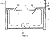
Фиг.8 изображает вид, схематически иллюстрирующий поток воздуха, подаваемого в выдвижной ящик 30 устройством 40 для подачи воздуха.FIG. 8 is a view schematically illustrating the flow of air supplied to the
Как показано на фиг.8, воздух, выходящий через выпускное отверстие 49, проходит в отверстие 15 для впуска нагретого воздуха, и воздух проходит по направлению к боковой верхней части внутри выдвижного ящика 30 через центральную нижнюю часть. Поэтому мертвая зона внутри выдвижного ящика 30, в которую воздух не проходит, может быть максимально уменьшена.As shown in FIG. 8, the air exiting through the
Кроме того, как показано на фиг.2, нижняя сторона перегородки 16 может содержать выступающую вверх часть, окружающую утопленную часть на верхней стороне перегородки 16. Эта выступающая вверх часть может включать в себя наклонные части 162, выполненные с возможностью переориентации воздушного потока внутрь по направлению к центральной части перегородки 16, а также вниз от перегородки 16 и назад по направлению к выдвижному ящику 30. Это устройство обеспечивает рециркуляцию некоторой части воздуха, что может способствовать нагреванию, сушки или другой обработки белья в выдвижном ящике 30.In addition, as shown in FIG. 2, the lower side of the
Как показано на фиг.6, зазор 32 образован между перегородкой 16 и выдвижным ящиком 30 для обеспечения прохождения воздуха через него и выхода из выдвижного ящика 30 для последующего выхода из второго отделения 14 для обработки белья. Кроме того, если белье загружено на нижнюю поверхность выдвижного ящика 30, воздух может максимально контактировать с бельем.As shown in Fig.6, the
Нижняя часть выдвижного ящика 30 стремится переориентировать направленный вниз воздушный поток на наружную сторону во всех направлениях к боковым стенкам выдвижного ящика. Соответственно, боковые стенки выдвижного ящика стремятся переориентировать воздушный поток вверх по направлению к перегородке 16. В конечном счете, перегородка 16 стремится переориентировать воздушный поток внутрь по направлению к центральной части перегородки 16, где воздушный поток соединяется с направленным вниз воздушным потоком и рециркулирует.The lower part of the
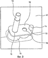
Как показано на фиг.3 и 4, устройство 40 для подачи воздуха в соответствии с данным вариантом осуществления может дополнительно содержать первый датчик 70 температуры, который измеряет температуру нагретого воздуха. Нагревательным устройством 60 можно управлять в соответствии со значениями температуры, измеренными первым датчиком 70, для подачи нагретого воздуха.As shown in FIGS. 3 and 4, the
Датчик 70 может быть установлен в заданной части внутри канала, и подразумевается, что датчик 70 температуры установлен в конце канала, то есть рядом с выпускным отверстием 49. Работой нагревательного устройства 60 можно управлять в соответствии с температурами, измеренными датчиком 70 температуры, так что температуру воздуха, подаваемого во второе отделение 14 для обработки белья, можно регулировать.The
Датчик 70 температуры может быть установлен посредством принудительной вставки или с использованием клея. Подразумевается, что датчик 70 температуры прикреплен достаточно надежно, чтобы выдерживать давление воздуха, выдуваемого вентилятором 51. Со ссылкой на соответствующие чертежи будет описан датчик 70 температуры.The
Фиг.9 изображает перспективный вид, иллюстрирующий крепежное устройство для закрепления датчика 70 температуры, показанного сверху под кожухом 42.Fig. 9 is a perspective view illustrating a mounting device for fixing a
Как показано на фиг.9, крепежное устройство содержит крепежную накладку 72 для закрепления датчика 70 температуры, и фиксирующий элемент 74, проходящий от кожуха 42, для фиксации положения крепежной накладки 72.As shown in FIG. 9, the mounting device includes a mounting
Датчик 70 температуры может проходить через сквозное отверстие 71, образованное в крепежной накладке 72. Датчик 70 температуры может также закрепляться посредством принудительной вставки в сквозное отверстие 71 или с помощью клея. Крепежное отверстие 76 может быть образовано в крепежной накладке 72 для прикрепления датчика 70 температуры к кожуху 42. Крепежный элемент (не показан) походит в крепежное отверстие 76 и кожух, так что крепежная накладка 72 прикрепляется к кожуху 42. Таким образом, датчик 70 температуры сначала прикрепляется к кожуху 42 и затем к крепежной накладке. Кожух 42 может дополнительно содержать крепежную часть 75, через которую проходит датчик 70 температуры. Датчик 70 температуры проходит через крепежную часть 75, и он надежно прикрепляется к крепежной накладке 72.The
Если крепежная накладка 72 соединяется с кожухом 42, может дополнительно быть образован фиксирующий элемент 74. Фиксирующий элемент 74 соединяется с кожухом 42 и фиксирует положение крепежной накладки 72. Фиксирующий элемент 74 может проходить от кожуха 42. Фиксирующая выемка 73, соответствующая фиксирующему элементу 74, может быть образована в крепежной накладке 72. Фиксирующая выемка 73 образована на заданной части крепежной накладки 72. фиксирующий элемент 74 вставляется в фиксирующую выемку 73. Когда конец датчика 70 температуры вставлен в сквозное отверстие 71, и фиксирующий элемент 74 установлен в фиксирующей выемке 73, крепежная накладка 72 фиксируется, и затем рабочий может пропустить крепежный элемент через крепежное отверстие 76.If the
Как показано на фиг.4, машина для обработки белья управляет работой нагревательного устройства 60 в соответствии с температурой воздуха, измеренной датчиком 70 температуры. Следовательно, температура нагретого воздуха, подаваемого во второе отделение 14 для обработки белья, может регулироваться. Для управления нагревательным устройством 60 с помощью температуры нагретого воздуха, измеряемой датчиком 70 температуры, может быть установлено одно устройство управления, или могут быть установлены, по меньшей мере, два устройства управления.As shown in FIG. 4, the laundry machine controls the operation of the
Если установлено, по меньшей мере, два устройства управления, например, основное устройство управления и вспомогательное устройство управления, основное устройство управления управляет всей работой барабана 20 и устройства 40 для подачи воздуха. Температуры, измеренные датчиком 70 температуры, могут передаваться в основное устройство управления.If at least two control devices are installed, for example, a main control device and an auxiliary control device, the main control device controls the entire operation of the
Основное устройство управления может управлять нагревательным устройством 60 и вентилятором 51 устройства 40 для подачи воздуха в соответствии с соответствующим сигналом, передаваемым датчиком 70 температуры. В этом случае сигнал команды, генерируемый основным устройством управления, передается во вспомогательное устройство управления, расположенное в устройстве 40 для подачи воздуха. Следовательно, вспомогательное устройство управления управляет нагревательным устройством 60 и вентилятором 51 в соответствии с сигналом команды основного устройства управления. При приеме сигнала команды из основного устройства управления, вспомогательное устройство управления может выполнять только двухпозиционное управление нагревательным устройством 60 или вентилятором 51 для упрощения данной конфигурации.The main control device can control the
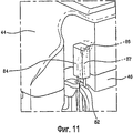
Как упоминалось выше, устройство 40 для подачи воздуха может включать в себя элементы, такие как вентилятор 51 и нагревательное устройство 60, и эти элементы приводятся в действие электричеством. Поэтому провода для подачи электричества в эти элементы могут быть расположены снаружи или внутри устройства 40 для подачи воздуха. Если рабочий выполняет ремонт или техническое обслуживание устройства для подачи воздуха, в котором расположены провода, отдельно рассредоточенные, эти провода могут создавать помехи для выполнения работы. Кроме того, отдельно рассредоточенные провода могут стать причиной короткого замыкания из-за воды, стекающей с барабана 20, установленного над устройством 40 для подачи воздуха. В соответствии с данным вариантом осуществления, устройство 40 для подачи воздуха может содержать фиксирующий элемент для фиксации проводов в кожухе 42.As mentioned above, the
Фиг.3 изображает элемент для фиксации проводов, выполненный в виде крючка 86 для фиксации проводов, расположенных вдоль наружной стороны устройства 40 для подачи воздуха, и, по меньшей мере, один элемент 82 и 84 для фиксации проводов для закрепления проводов, соединяющих внутреннюю часть устройства 40 для подачи воздуха с наружной стороной. Эта конфигурация будет описана подробно со ссылкой на соответствующий чертеж.Figure 3 depicts an element for fixing wires, made in the form of a
Как показано на фиг.10, фиксирующий крючок 86 образован в заданной части кожуха 42 как одно целое с кожухом 42. В результате, провода 87, расположенные вдоль наружной стороны кожуха 42 устройства 40 для подачи воздуха, могут вставляться в фиксирующий крючок 86 без рассредоточения.As shown in FIG. 10, a locking
Фиг.11 изображает увеличенный перспективный вид, иллюстрирующий фиксирующие элементы 82 и 84 для крепления проводов, соединяющих внутреннюю часть с наружной стороной устройства 40 для подачи воздуха. Так как нагревательное устройство 60 расположено в кожухе 42 устройства 40 для подачи воздуха, провода, подающие электричество в нагревательное устройство 60, могут проходить наружу из внутренней части кожуха 42, так что фиксирующий элемент, изображенный на фиг.10, может закреплять провода.11 is an enlarged perspective view illustrating the fixing
Как показано на фиг.11, фиксирующий элемент включает в себя фиксирующий паз 82, образованный в кожухе 42, и сквозное отверстие 86, соединяющее внутреннюю часть кожуха 42 с наружной стороной, для прохождения провода 87 через него.As shown in FIG. 11, the locking element includes a locking
Провода 87 неподвижно вставляются в фиксирующий паз 82 с наружной стороны кожуха 42. Следовательно, провода 87, зафиксированные в фиксирующем пазу 82, проходят через сквозное отверстие 86, образованное в кожухе 42, и они размещаются внутри кожуха 42. Провода 87, проходящие в кожух 42, соединяются с нагревательным устройством 60, и они подают электричество.The
Если провода проходят с наружной стороны во внутреннюю часть кожуха 42, вода, стекающая с барабана 20, будет контактировать с проводами 87 или пройдет в кожух через сквозное отверстие 86. Поэтому устройство 84 для предотвращения проникновения воды может быть дополнительно установлено в кожухе 42 для предотвращения проникновения воды в кожух 42 через сквозное отверстие 86. Устройство 84 для предотвращения проникновения воды может быть выполнено рядом со сквозным отверстием 86. Подразумевается, что устройство 84 для предотвращения проникновения воды закрывает сквозное отверстие 86, так что стекающая вода не может проходить по направлению к сквозному отверстию 86. Устройство 84 для предотвращения проникновения воды может быть вариантом осуществления описанного выше устройства для предотвращения проникновения воды.If the wires pass from the outside to the inside of the
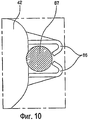
Когда пользователь открывает выдвижной ящик 30 во время подачи воздуха через выпускное отверстие 49 устройства 40 для подачи воздуха, случается так, что рука пользователя лишь входит в выпускное отверстие 49 и получает ожог. Поэтому может быть установлено устройство для предотвращения вхождения руки пользователя или посторонних веществ в выпускное отверстие 49 устройства 40 для подачи воздуха, и оно будет описано ниже со ссылкой на соответствующий чертеж.When the user opens the
Как показано на фиг.12, устройство 40 для подачи воздуха может содержать направляющее ребро 96, предотвращающее вхождение руки пользователя или посторонних веществ в устройство 40 для подачи воздуха через выпускное отверстие 49.As shown in FIG. 12, the
Направляющее ребро 96 образовано на выпускном отверстии 49, и оно предотвращает вхождение руки пользователя или посторонних веществ в выпускное отверстие 49. Например, направляющее ребро 96 может быть образовано в форме решетки, как показано на фиг.11, и форма направляющего ребра 96 может быть различной, не ограничиваясь формой решетки. В данном документе направляющее ребро 96 используется для увеличения жесткости и прочности кожуха 42, а также для предотвращения всасывания посторонних веществ в устройство 40 для подачи воздуха через выпускное отверстие 49.A
Устройство 40 для подачи воздуха может включать в себя электрические устройства, такие как электродвигатель (150, см. фиг.14), приводящий в действие вентилятор 51, вспомогательное устройство управления (не показано). Такие электрические устройства могут устанавливаться в кожухе. Однако электрические устройства будут располагаться на наружной стороне кожуха, так как кожух 42 может иметь относительно небольшое внутреннее пространство. В соответствии с данным вариантом осуществления, электрические устройства расположены на нижней стороне кожуха 42. Поэтому подразумевается, что устройство 40 для подачи воздуха содержит устройство для предотвращения доступа воды, предотвращающее попадание воды на электрические устройства. Это устройство будет описано ниже.The
Фиг.13 изображает перспективный вид, иллюстрирующий заднюю поверхность устройства 40 для подачи воздуха.13 is a perspective view illustrating a rear surface of the
Как показано на фиг.13, устройство для предотвращения доступа воды включает в себя выступающую часть 98, образованную в кожухе 42. Выступающая часть 98 защищает электрические устройства, такие как электродвигатель 150 вентилятора 51, от попадания воды. Конкретно, выступающая часть 98 проходит наружу от кромки кожуха 42 с направленным вниз изгибом. Даже если вода стекает с барабана 29, вода направляется вдоль выступающей части 98 с поверхности кожуха 42 на перегородку 16. Следовательно, стекающая вода не может проходить в электродвигатель 150 и вспомогательное устройство управления, расположенные на нижней стороне кожуха 42.As shown in FIG. 13, the device for preventing water from entering includes a protruding
Как показано на фиг.4, нижний кожух 46 содержит опорную часть 46', проходящую вниз. Круглые выступы 92 и ребра 90, упомянутые выше, могут быть образованы на конце опорной части 46'. Опорная часть 46' в соответствии с данным вариантом осуществления выполнена с возможностью закрытия нижней стороны кожуха 42. Вода, стекающая вниз, не может проходить по направлению к электродвигателю 150 и вспомогательному устройству управления, расположенным на нижней стороне кожуха 42. В результате, опорная часть 46', закрывающая нижнюю сторону кожуха 42, может быть вариантом осуществления устройство для предотвращения доступа воды.As shown in FIG. 4, the
Фиг.14 и 15 изображают перспективный вид, иллюстрирующий кожух 42 устройства 40 для подачи воздуха.14 and 15 are a perspective view illustrating a
Как показано на фиг.14 и 15, установочная часть 140 может быть образована на нижней поверхности кожуха 46. Вспомогательное устройство управления может быть установлено в установочной части 140. В данном документе установочная часть 140 может быть разделена пластиной 142, расположенной на нижней поверхности нижнего кожуха 46. Пластина 142 может быть выполнена из отдельного элемента или как одно целое с нижним кожухом 46.As shown in FIGS. 14 and 15, the mounting
Следовательно, вспомогательное устройство управления может быть установлено в установочной части 140. Подразумевается, что, по меньшей мере, один крепежный круглый выступ 110 может быть образован, и крепежный круглый выступ 110 прикрепляется к вспомогательному устройству управления для точного определения положения вспомогательного устройства управления. В данном документе крепежный круглый выступ 110 не показан на фиг.14.Therefore, the auxiliary control device can be installed in the
Если вспомогательное устройство управления содержит кожух 120 и рабочее устройство (не показано), устанавливаемое в кожухе 120, рабочий прикрепляет кожух 120 к крепежному круглому выступу 110 с помощью крепежного элемента, и рабочее устройство устанавливает в крышку 120. В данном документе только кожух вспомогательного устройства управления изображен на фиг.14 для удобства. В результате, рабочий может собрать вспомогательное устройство управления надежно и эффективно, и время, необходимое для сборки, может быть уменьшено.If the auxiliary control device includes a
Фиг. 16 изображает перспективный вид, иллюстрирующий кожух 42 устройства 40 для подачи воздуха. Вентилятор 51, расположенный в кожухе 42, вращается электродвигателем 150, и электродвигатель 150 может быть установлен на нижней поверхности нижнего кожуха 46. Вода будет стекать с барабана 20, и подразумевается, что электрические устройства, такие как электродвигатель 150, расположены в нижнем кожухе 46.FIG. 16 is a perspective view illustrating a
Кроме того, оконечное устройство 152 может быть расположено на электродвигателе 150, и провода для подачи электричества соединяются с оконечным устройством 152. Так как оконечное устройство 152 подает электричество в электродвигатель 150, температура оконечного устройства 152 может повышаться во время работы электродвигателя 150. Если оконечное устройство 152 непосредственно контактирует с кожухом 42 устройства 40 для подачи воздуха, или оно расположено рядом с кожухом 42, тепло оконечного устройства 152 будет деформировать кожух.In addition, the
Таким образом, подразумевается, что электродвигатель 150 расположен на заданном расстоянии от кожуха 42. Конкретно, электродвигатель 150 может быть соединен с прокладкой 160, расположенной в нижнем кожухе 46. То есть один конец прокладки 160 соединяется с нижним кожухом 46, а другой конец прокладки 160 соединяется с электродвигателем 150. Можно сказать, что прокладка 160 не только поддерживает электродвигатель 150, но также размещает оконечное устройство 152 электродвигателя 150 на расстоянии от нижнего кожуха 46.Thus, it is understood that the
Работа машины для обработки белья с указанной конфигурацией будет описана ниже со ссылкой на чертежи.The operation of the machine for processing linen with the specified configuration will be described below with reference to the drawings.
Прежде всего, пользователь загружает белье в выдвижной ящик 30 корпуса 10 и выбирает желаемый режим, например, режим подачи горячего воздуха или режим вентиляции только для вентиляции. В случае режима подачи горячего воздуха, устройство 40 для подачи воздуха нагревает воздух и подает горячий воздух во второе отделение 14, то есть выдвижной ящик 30. В данном документе датчик 70 температуры измеряет температуру воздуха, и устройство 40 для подачи воздуха управляется в соответствии с температурой, измеренной датчиком 70 температуры.First of all, the user loads the laundry into the
Специалистам в данной области техники будет понятно, что возможны различные модификации и изменения в настоящем изобретении без отхода от сущности или объема настоящего изобретения. Таким образом, подразумевается, что настоящее изобретение включает модификации и изменения настоящего изобретения при условии, что они входят в объем прилагаемой формулы изобретения и ее эквивалентов.Those skilled in the art will understand that various modifications and changes are possible in the present invention without departing from the spirit or scope of the present invention. Thus, it is understood that the present invention includes modifications and changes of the present invention, provided that they are included in the scope of the attached claims and their equivalents.
Claims (12)
корпус,
перегородку для разделения внутреннего пространства корпуса на первое отделение для обработки белья, выполненное с возможностью размещения в нем белья, и второе отделение для обработки белья, выполненное с возможностью размещения в нем белья, и
устройство для подачи воздуха, установленное на перегородке и выполненное с возможностью подачи воздуха во второе отделение для обработки белья, причем устройство для подачи воздуха содержит вентилятор, нагревательный элемент и кожух, при этом вентилятор, нагревательный элемент, воздухоприемное отверстие и воздуховыпуск расположены в кожухе.1. Machine for processing linen, containing:
case
a partition for dividing the inner space of the housing into a first laundry treatment compartment adapted to accommodate laundry, and a second laundry processing compartment configured to accommodate laundry, and
an air supply device mounted on a partition and configured to supply air to the second laundry treatment compartment, the air supply device comprising a fan, a heating element and a casing, the fan, a heating element, an air inlet and an air outlet being located in the casing.
Applications Claiming Priority (4)
| Application Number | Priority Date | Filing Date | Title |
|---|---|---|---|
| KR20080040600 | 2008-04-30 | ||
| KR10-2008-0040600 | 2008-04-30 | ||
| KR10-2008-0040609 | 2008-04-30 | ||
| KR20080040609 | 2008-04-30 |
Publications (1)
| Publication Number | Publication Date |
|---|---|
| RU2404309C1 true RU2404309C1 (en) | 2010-11-20 |
Family
ID=40858283
Family Applications (1)
| Application Number | Title | Priority Date | Filing Date |
|---|---|---|---|
| RU2009116550/21A RU2404309C1 (en) | 2008-04-30 | 2009-04-29 | Linen processing machine |
Country Status (9)
| Country | Link |
|---|---|
| US (1) | US8297082B2 (en) |
| EP (1) | EP2113596B1 (en) |
| CN (1) | CN101570930B (en) |
| AT (1) | ATE533881T1 (en) |
| AU (1) | AU2009201737B9 (en) |
| BR (1) | BRPI0905815B1 (en) |
| CA (1) | CA2664883C (en) |
| ES (1) | ES2374768T3 (en) |
| RU (1) | RU2404309C1 (en) |
Families Citing this family (13)
| Publication number | Priority date | Publication date | Assignee | Title |
|---|---|---|---|---|
| DE102006002713A1 (en) * | 2005-03-18 | 2006-10-12 | BSH Bosch und Siemens Hausgeräte GmbH | Front assembly for a laundry drying machine |
| US7913419B2 (en) * | 2005-12-30 | 2011-03-29 | Whirlpool Corporation | Non-tumble clothes dryer |
| DE102007007354B4 (en) | 2006-02-20 | 2013-10-10 | Lg Electronics Inc. | Clothes dryer and method of control |
| KR100830514B1 (en) | 2006-06-12 | 2008-05-21 | 엘지전자 주식회사 | laundry dryer and method for controlling the same |
| US7997006B2 (en) * | 2007-01-12 | 2011-08-16 | Lg Electronics Inc. | Laundry machine and control method thereof |
| ATE533880T1 (en) * | 2008-04-30 | 2011-12-15 | Lg Electronics Inc | WASHING MACHINE |
| KR101608760B1 (en) | 2008-04-30 | 2016-04-04 | 엘지전자 주식회사 | Laundry machine |
| ES2374768T3 (en) | 2008-04-30 | 2012-02-21 | Lg Electronics Inc. | WASHING MACHINE. |
| KR20170002889A (en) * | 2015-06-30 | 2017-01-09 | 엘지전자 주식회사 | Laundry Treating Apparatus |
| WO2018124631A1 (en) | 2017-01-02 | 2018-07-05 | Samsung Electronics Co., Ltd. | Dual drying apparatus |
| CN112376240B (en) * | 2020-05-22 | 2023-05-12 | 合肥美的洗衣机有限公司 | Clothes treating apparatus |
| US11591735B2 (en) * | 2020-10-26 | 2023-02-28 | Terron Allen | Washer and dryer combination |
| TR202021290A1 (en) * | 2020-12-22 | 2022-07-21 | Vestel Beyaz Esya Sanayi Ve Ticaret Anonim Sirketi | A desiccant device with a mounting plate. |
Family Cites Families (172)
| Publication number | Priority date | Publication date | Assignee | Title |
|---|---|---|---|---|
| US2165487A (en) | 1935-12-02 | 1939-07-11 | American Laundry Mach Co | Garment cleaning system |
| US2369366A (en) | 1941-02-11 | 1945-02-13 | Leo M O'neill | Drier and method of drying |
| US2351429A (en) | 1942-09-21 | 1944-06-13 | Huebsch Mfg Company | Drying apparatus |
| US2486058A (en) | 1945-03-16 | 1949-10-25 | American Machine & Metals | Air drying tumbler for laundry |
| US2566488A (en) | 1945-04-28 | 1951-09-04 | Murray Corp | Combined fabric washing and drying unit |
| US2543579A (en) | 1946-03-22 | 1951-02-27 | Lovell Mfg Co | Drier |
| US2547238A (en) | 1947-08-12 | 1951-04-03 | Tremblay Gerard | Drying apparatus |
| US2611192A (en) | 1949-11-21 | 1952-09-23 | American Laundry Mach Co | Lint remover for driers |
| US2722057A (en) | 1950-12-09 | 1955-11-01 | Ralph G Pugh | Clothes dryer |
| US2707837A (en) | 1951-02-03 | 1955-05-10 | Gen Electric | Clothes drier |
| US2687578A (en) | 1951-11-10 | 1954-08-31 | W M Cissell Mfg Company Inc | Apparatus for drying fabrics |
| US2742708A (en) | 1952-07-12 | 1956-04-24 | Gen Motors Corp | Domestic appliance |
| US2727315A (en) | 1952-09-20 | 1955-12-20 | Gen Motors Corp | Domestic appliance |
| US2716820A (en) | 1952-11-26 | 1955-09-06 | Temco Inc | Drying apparatus |
| US2867430A (en) | 1952-12-31 | 1959-01-06 | Murray Corp | Laundry dryers |
| US2752004A (en) | 1953-06-25 | 1956-06-26 | Murray Corp | Laundry dryers |
| US2817157A (en) | 1954-07-16 | 1957-12-24 | Gen Motors Corp | Domestic appliance |
| US2813353A (en) | 1954-09-10 | 1957-11-19 | Gen Electric | Clothes dryer lint separator |
| US2817501A (en) | 1955-04-04 | 1957-12-24 | Philco Corp | Laundry apparatus |
| US2816429A (en) | 1955-04-29 | 1957-12-17 | Kurlancheek Erwin | Automatic washer-dryer |
| US2795055A (en) | 1955-05-18 | 1957-06-11 | American Laundry Mach Co | Lint remover means for driers |
| US2903799A (en) | 1955-06-21 | 1959-09-15 | Philco Corp | Drying apparatus |
| US2861355A (en) | 1955-09-23 | 1958-11-25 | Pennsylvania Range Boiler Co | Laundry drying machines |
| US3000108A (en) | 1956-06-11 | 1961-09-19 | Whirlpool Co | Coaxial flow drier |
| US3023514A (en) | 1956-07-02 | 1962-03-06 | George M Gibson | Clothes dryer |
| US2843945A (en) | 1956-07-02 | 1958-07-22 | Gen Motors Corp | Domestic appliance |
| US2904895A (en) | 1956-07-25 | 1959-09-22 | Gen Electric | Laundry machine with basket stop means |
| US2985967A (en) | 1957-11-01 | 1961-05-30 | Everett F Pataillot | Clothes dryer |
| US3001295A (en) | 1957-11-22 | 1961-09-26 | Gen Motors Corp | Clothes drier with lint eliminator |
| US3064358A (en) | 1958-02-17 | 1962-11-20 | Anthony A Giuffre | Clothes drying device |
| US3061942A (en) | 1958-12-30 | 1962-11-06 | Philco Corp | Fabric dryer with lint burning means |
| US3121000A (en) | 1960-11-09 | 1964-02-11 | Philco Corp | Laundry dryer or washer-dryer |
| FR1473011A (en) | 1965-10-28 | 1967-03-17 | Laundry and clothes dryer | |
| US3383776A (en) | 1966-05-25 | 1968-05-21 | Topper Tools Inc | Wall-mounted clothing drier unit |
| US3402477A (en) | 1966-11-07 | 1968-09-24 | Philco Ford Corp | Dual compartment laundry apparatus |
| US3555701A (en) | 1969-05-15 | 1971-01-19 | Philco Ford Corp | Laundry apparatus |
| US3579851A (en) | 1969-05-19 | 1971-05-25 | Westinghouse Electric Corp | Pop-out lint trap and door interlock for laundry apparatus |
| US3789514A (en) | 1972-07-24 | 1974-02-05 | Maytag Co | Bulkhead filter assembly |
| US3840998A (en) | 1973-08-29 | 1974-10-15 | Whirlpool Co | Removable clothers basket for dryer |
| DE2451339C2 (en) | 1974-10-25 | 1982-02-18 | Bosch-Siemens Hausgeräte GmbH, 7000 Stuttgart | Combination of a washing machine with a condensation dryer |
| GB1545078A (en) | 1976-11-23 | 1979-05-02 | Servis Domestic Appliances Ltd | Combined washing and drying machine |
| JPS59214494A (en) | 1983-05-23 | 1984-12-04 | 株式会社日立製作所 | Drum type clothing dryer |
| US4653200A (en) | 1986-03-05 | 1987-03-31 | Whirlpool Corporation | Lint screen shield assembly for a dryer |
| DE59007317D1 (en) | 1989-02-03 | 1994-11-03 | Zanker Gmbh | LAUNDRY DRYER. |
| SU1687682A1 (en) | 1989-09-22 | 1991-10-30 | Предприятие П/Я Г-4805 | Washing machine |
| US5062219A (en) | 1991-02-12 | 1991-11-05 | Speed Queen Company | Air flow apparatus for clothes dryer |
| US5165181A (en) | 1992-01-15 | 1992-11-24 | Acosta Sr Corby A | Shoe dryer |
| US5443538A (en) | 1993-01-22 | 1995-08-22 | Little; David H. | Method and apparatus for drying small articles of wearing apparel |
| CN2157212Y (en) | 1993-04-15 | 1994-02-23 | 南海华南干衣机有限公司 | Double-chamber electric heating clothing drying cabinet |
| US5369892A (en) | 1993-06-04 | 1994-12-06 | Dhaemers; Gregory L. | Armoire |
| KR950025142A (en) | 1994-02-07 | 1995-09-15 | 배순훈 | Drying control method of washing machine |
| US5560120A (en) | 1995-04-20 | 1996-10-01 | Whirlpool Corporation | Lint handling system |
| US5784901A (en) | 1995-08-31 | 1998-07-28 | Sanyo Electric Co., Ltd. | Washing machine |
| US20070151312A1 (en) | 2005-12-30 | 2007-07-05 | Bruce Beihoff C | Modular fabric revitalizing system |
| US8844160B2 (en) | 1997-04-29 | 2014-09-30 | Whirlpool Corporation | Modular fabric revitalizing system |
| US6151795A (en) | 1997-06-13 | 2000-11-28 | Mmats Incorporated | Flat material dryer |
| US6016610A (en) | 1998-04-15 | 2000-01-25 | Maytag Corporation | Self-cleaning lint trap and gravity assisted lint trap |
| US6374644B1 (en) | 1998-08-18 | 2002-04-23 | E Sportra Wash Systems Inc. | Equipment washer |
| US6732553B2 (en) | 1998-08-18 | 2004-05-11 | Esporta Wash Systems, Inc. | Equipment washer |
| US6094839A (en) | 1999-05-11 | 2000-08-01 | Nikolov; Dimitar Nikolov | Footwear drying apparatus |
| KR100339006B1 (en) | 2000-03-11 | 2002-05-31 | 구자홍 | Drum Washing Machine |
| US7624600B2 (en) | 2000-07-25 | 2009-12-01 | Whirlpool Corporation | Modular laundry system with horizontally arranged cabinet module |
| US20020017117A1 (en) | 2000-07-25 | 2002-02-14 | Sunshine Richard A. | Integrated laundry center |
| AU760902B2 (en) | 2000-10-12 | 2003-05-22 | Lg Electronics Inc. | Drawer-type washing machine |
| EP1215330B1 (en) | 2000-12-14 | 2005-03-23 | Whirlpool Corporation | Appliance for cleaning and refreshing fabrics with a built-in working indicator |
| US20030079368A1 (en) | 2001-10-25 | 2003-05-01 | Hoffman Karl H. | Flat material dryer |
| EP1353004A1 (en) | 2002-04-09 | 2003-10-15 | Bonferraro S.p.A. | Washing machine with self-cleaning drying circuit |
| US6671978B1 (en) | 2002-11-13 | 2004-01-06 | Mcgowan Ian A | Combination washer/dryer |
| RU2317357C2 (en) | 2003-01-20 | 2008-02-20 | Виктор Александрович Шапиро | Washing machine |
| DE20302572U1 (en) * | 2003-02-18 | 2003-04-24 | Hansen, Nikolaus, 77880 Sasbach | Drawer unit forming the lower section of a washing machine cabinet |
| ITTO20030236A1 (en) | 2003-03-28 | 2004-09-29 | Merloni Elettrodomestici Spa | WASHING MACHINE, IN PARTICULAR LOADING |
| JP2005087712A (en) | 2003-08-08 | 2005-04-07 | Sharp Corp | Water supply device, water supply method, water spray device with water supply device, and washing machine with water supply device |
| US7673358B2 (en) | 2003-09-26 | 2010-03-09 | Miele & Cie Kg. | Method of controlling the revolutions of the drum of a program controlled laundry machine |
| WO2005032322A2 (en) | 2003-09-29 | 2005-04-14 | Self Propelled Research And Development Specialists, Llc | Heat pump clothes dryer |
| EP1524356A1 (en) | 2003-10-18 | 2005-04-20 | Lg Electronics Inc. | Drum type washing and drying apparatus |
| EP1541741B1 (en) | 2003-12-09 | 2016-08-10 | LG Electronics, Inc. | Laundry dryer |
| EP1541743B1 (en) | 2003-12-10 | 2010-10-06 | LG Electronics, Inc. | Laundry dryer with dry board |
| US7036243B2 (en) | 2003-12-22 | 2006-05-02 | Lg Electronics Inc. | Laundry dryer and condenser assembly thereof |
| US7748139B2 (en) | 2003-12-22 | 2010-07-06 | Lg Electronics Inc. | Laundry dryer and drum supporting assembly thereof |
| EP1548177B1 (en) | 2003-12-22 | 2010-10-06 | LG Electronics, Inc. | Condensed water storing apparatus of a dryer |
| KR101041904B1 (en) * | 2004-06-04 | 2011-06-15 | 주식회사 대우일렉트로닉스 | Stand for drum type washing machine having a drying apparatus |
| KR101093878B1 (en) | 2004-06-05 | 2011-12-13 | 엘지전자 주식회사 | A drum apparatus of a dryer |
| KR101093988B1 (en) | 2004-06-05 | 2011-12-15 | 엘지전자 주식회사 | A sealing apparatus of the door lint filter for a drying machine |
| EP1621660B1 (en) | 2004-06-14 | 2010-03-10 | Samsung Electronics Co., Ltd. | Supporter for clothes washing machine and clothes drying apparatus |
| US20100231506A1 (en) | 2004-09-07 | 2010-09-16 | Timothy Pryor | Control of appliances, kitchen and home |
| KR20060031164A (en) | 2004-10-07 | 2006-04-12 | 엘지전자 주식회사 | Drum type washing machine for having dry function |
| KR20060033065A (en) | 2004-10-14 | 2006-04-19 | 엘지전자 주식회사 | (a) condensing type dryer and method of controlling the same |
| US20070151300A1 (en) | 2005-12-30 | 2007-07-05 | Sunshine Richard A | Modular laundry system with horizontal module spanning two laundry appliances |
| KR100595263B1 (en) | 2004-11-10 | 2006-07-03 | 엘지전자 주식회사 | operating method of Refresh Mode in washing device |
| KR100700780B1 (en) | 2004-11-12 | 2007-03-27 | 엘지전자 주식회사 | A combined drying and washing machine and control method about the machine |
| KR100738714B1 (en) | 2004-12-10 | 2007-07-12 | 엘지전자 주식회사 | Drum type washing machine for having dry function |
| US6978556B1 (en) | 2005-01-19 | 2005-12-27 | Ephelius Cornelious | Combination washing machine and dryer |
| WO2006091057A1 (en) | 2005-02-28 | 2006-08-31 | Lg Electronics Inc. | Refresher and machine for washing or drying with the same |
| US20080271500A1 (en) | 2005-03-25 | 2008-11-06 | Lg Electronics Inc. | Laundry Machine |
| KR101163227B1 (en) | 2005-04-28 | 2012-07-05 | 엘지전자 주식회사 | Laundry dryer |
| US20070062513A1 (en) | 2005-09-21 | 2007-03-22 | Gagas John M | Cooking system with ventilator and blower |
| US7404303B1 (en) | 2005-11-14 | 2008-07-29 | Barbosa Domingos D | Automatic drop washer/dryer |
| CN1966839A (en) * | 2005-11-14 | 2007-05-23 | 乐金电子(天津)电器有限公司 | Heater for clothes drier |
| US7497030B2 (en) | 2005-11-23 | 2009-03-03 | Belgard Richard A | Integral lint filter for clothes dryers |
| KR100652459B1 (en) | 2005-11-25 | 2006-12-01 | 엘지전자 주식회사 | One body-type washing and drying machine |
| US20070163094A1 (en) | 2005-12-30 | 2007-07-19 | Tremitchell Wright | Fabric revitalizing method using mist |
| US7665227B2 (en) | 2005-12-30 | 2010-02-23 | Whirlpool Corporation | Fabric revitalizing method using low absorbency pads |
| US20070163095A1 (en) | 2005-12-30 | 2007-07-19 | Mcallister Karl D | Fabric revitalizing system and treatment appliance |
| US7913419B2 (en) | 2005-12-30 | 2011-03-29 | Whirlpool Corporation | Non-tumble clothes dryer |
| US20070163096A1 (en) | 2005-12-30 | 2007-07-19 | Mcallister Karl D | Fluid delivery system for a fabric treatment appliance |
| US7562543B2 (en) | 2005-12-30 | 2009-07-21 | Whirlpool Corporation | Vertical laundry module with backsplash |
| US20070163098A1 (en) | 2005-12-30 | 2007-07-19 | Tomasi Donald M | Drum with low absorbency textured surface for a fabric treatment appliance |
| US7735345B2 (en) | 2005-12-30 | 2010-06-15 | Whirlpool Corporation | Automatic fabric treatment appliance with a manual fabric treatment station |
| US20070151041A1 (en) | 2005-12-30 | 2007-07-05 | Mcallister Karl D | Control process for a revitalizing appliance |
| US20070151311A1 (en) | 2005-12-30 | 2007-07-05 | Mcallister Karl D | Fabric revitalizing system |
| US7921578B2 (en) | 2005-12-30 | 2011-04-12 | Whirlpool Corporation | Nebulizer system for a fabric treatment appliance |
| US20070163097A1 (en) | 2005-12-30 | 2007-07-19 | Metcalfe Ld | Low absorbency pad system for a fabric treatment appliance |
| US8491159B2 (en) | 2006-03-28 | 2013-07-23 | Wireless Environment, Llc | Wireless emergency lighting system |
| DE102006019608A1 (en) | 2006-04-25 | 2007-11-08 | Miele & Cie. Kg | System consisting of domestic appliance with base or sub-assembly |
| DE112007001116B4 (en) | 2006-06-12 | 2013-11-14 | Lg Electronics Inc. | Clothing dryer and method of controlling the same |
| KR100830514B1 (en) | 2006-06-12 | 2008-05-21 | 엘지전자 주식회사 | laundry dryer and method for controlling the same |
| EP1873298B1 (en) | 2006-06-27 | 2012-06-27 | Lg Electronics Inc. | Steam generating device and washing machine having the same |
| DE602007009242D1 (en) | 2006-07-18 | 2010-10-28 | Lg Electronics Inc | DRIER |
| US8973414B2 (en) | 2006-07-18 | 2015-03-10 | Lg Electronics Inc. | Laundry treating apparatus |
| AU2007277583B2 (en) | 2006-07-25 | 2011-10-27 | Lg Electronics Inc. | Auxiliary laundry treating machine and multiple laundry treating machine including the same |
| US20100115784A1 (en) | 2006-07-28 | 2010-05-13 | Lg Electronics Inc. | Multiple laundry treating machine and control method thereof |
| BRPI0715351A2 (en) | 2006-07-28 | 2013-06-18 | Lg Eletronics Inc | Underwear Washing Machine |
| EP2054545B1 (en) | 2006-07-28 | 2016-08-31 | LG Electronics Inc. | Laundry dryer |
| KR101265623B1 (en) | 2006-08-22 | 2013-05-22 | 엘지전자 주식회사 | Pedestal Drying Machine Using PTC Heater |
| KR101265622B1 (en) | 2006-08-22 | 2013-05-22 | 엘지전자 주식회사 | Pedestal Drying Machine |
| CN104695189B (en) | 2006-08-23 | 2020-08-25 | Lg电子株式会社 | Composite laundry treating machine |
| ES2569337T3 (en) | 2006-08-23 | 2016-05-10 | Lg Electronics Inc. | Multiple washing machine |
| KR101221903B1 (en) | 2006-08-29 | 2013-01-15 | 엘지전자 주식회사 | Combined Laundry Machine Having Pedestal Drying Machines |
| KR101276815B1 (en) | 2006-08-29 | 2013-06-18 | 엘지전자 주식회사 | Pedestal Drying Machine |
| KR101276811B1 (en) | 2006-08-31 | 2013-06-18 | 엘지전자 주식회사 | Auxiliary dryer and multiple laundry machine including the same |
| KR101276818B1 (en) | 2006-08-31 | 2013-06-18 | 엘지전자 주식회사 | Auxiliary dryer and multiple laundry machine including the same |
| KR101314599B1 (en) | 2006-09-05 | 2013-10-04 | 엘지전자 주식회사 | multiple laundry treating machine |
| KR101253179B1 (en) | 2006-12-14 | 2013-04-12 | 엘지전자 주식회사 | laundry dryer |
| KR101203840B1 (en) | 2006-12-14 | 2012-11-21 | 엘지전자 주식회사 | laundry device and control method of the same |
| US7895770B2 (en) | 2006-12-15 | 2011-03-01 | Lg Electronics Inc. | Laundry machine |
| KR101341461B1 (en) | 2006-12-15 | 2013-12-16 | 엘지전자 주식회사 | Steam laundry dryer |
| KR101253180B1 (en) | 2006-12-15 | 2013-04-10 | 엘지전자 주식회사 | Steam laundry dryer |
| US20080141552A1 (en) | 2006-12-18 | 2008-06-19 | Lg Electronics Inc. | Steam dryer |
| KR101253181B1 (en) | 2006-12-26 | 2013-04-10 | 엘지전자 주식회사 | Dryer and Driving Method Thereof |
| KR101319881B1 (en) | 2007-01-10 | 2013-10-18 | 엘지전자 주식회사 | Multiple laundry treating machine |
| US7997006B2 (en) | 2007-01-12 | 2011-08-16 | Lg Electronics Inc. | Laundry machine and control method thereof |
| KR100830478B1 (en) | 2007-04-04 | 2008-05-20 | 엘지전자 주식회사 | Subsidiary drying apparatus |
| KR100857799B1 (en) * | 2007-04-04 | 2008-09-09 | 엘지전자 주식회사 | Subsidiary drying apparatus |
| CA2584573A1 (en) | 2007-04-11 | 2008-10-11 | Paul Regan | Storage and drying unit for storing and drying outerwear, sports clothing and equipment use |
| KR100873142B1 (en) | 2007-04-13 | 2008-12-09 | 엘지전자 주식회사 | Auxiliary Laundry treating machine and multiple treating system including the same |
| EP2150647B1 (en) | 2007-04-25 | 2016-09-07 | LG Electronics Inc. | Steam laundry dryer |
| ATE482309T1 (en) | 2007-04-25 | 2010-10-15 | Lg Electronics Inc | CLOTHES TREATMENT APPARATUS |
| KR100833865B1 (en) | 2007-04-25 | 2008-06-02 | 엘지전자 주식회사 | Steam laundry dryer and controlling method thereof |
| DE102008020671B4 (en) | 2007-04-25 | 2022-01-27 | Lg Electronics Inc. | garment treatment machine |
| KR101396971B1 (en) | 2007-05-02 | 2014-05-20 | 엘지전자 주식회사 | Steam Laundry Dryer |
| KR100896284B1 (en) | 2007-05-15 | 2009-05-08 | 엘지전자 주식회사 | Washing Machine |
| EP2000581B1 (en) | 2007-06-08 | 2014-02-19 | LG Electronics Inc. | Dryer |
| WO2009020328A2 (en) | 2007-08-03 | 2009-02-12 | Lg Electronics Inc. | Controlling method of clothes treating apparatus |
| KR101498027B1 (en) | 2008-04-01 | 2015-03-03 | 엘지전자 주식회사 | Laundry treating machine and control method of the same |
| KR101435797B1 (en) | 2007-08-03 | 2014-08-29 | 엘지전자 주식회사 | Cloth treating apparatus |
| KR100925735B1 (en) | 2007-09-03 | 2009-11-11 | 엘지전자 주식회사 | Supporter and pedestal and washing/drying machine having the same |
| KR100921461B1 (en) | 2007-11-02 | 2009-10-13 | 엘지전자 주식회사 | Control method of Dryer |
| EP2055824B1 (en) | 2007-11-02 | 2014-07-30 | LG Electronics Inc. | Dryer |
| KR101430456B1 (en) | 2007-11-12 | 2014-08-18 | 엘지전자 주식회사 | Supplemental cloth treating apparatus |
| DE102008056383B4 (en) | 2007-11-16 | 2015-08-20 | Lg Electronics Inc. | Steam laundry dryer |
| US7992321B2 (en) | 2007-12-19 | 2011-08-09 | Electrolux Home Products | Laundry dryer having three roller drum support system and reversing idler assembly |
| KR101608760B1 (en) | 2008-04-30 | 2016-04-04 | 엘지전자 주식회사 | Laundry machine |
| KR20090115015A (en) | 2008-04-30 | 2009-11-04 | 엘지전자 주식회사 | Cloth treating apparatus |
| ATE533880T1 (en) | 2008-04-30 | 2011-12-15 | Lg Electronics Inc | WASHING MACHINE |
| ES2374768T3 (en) | 2008-04-30 | 2012-02-21 | Lg Electronics Inc. | WASHING MACHINE. |
| US8201345B2 (en) | 2008-07-02 | 2012-06-19 | Whirlpool Corporation | Method for operating a cleanout cycle in a dispensing dryer |
| US20100000112A1 (en) | 2008-07-02 | 2010-01-07 | Whirlpool Corporation | Dispensing dryer dosing sensing |
| US8104191B2 (en) | 2008-07-31 | 2012-01-31 | Electrolux Home Products, Inc. | Laundry dryer providing moisture application during tumbling and reduced airflow |
| US8179011B2 (en) * | 2008-12-17 | 2012-05-15 | Asmo Co., Ltd. | Brushless motor |
| KR101070536B1 (en) | 2008-12-17 | 2011-10-05 | 엘지전자 주식회사 | Dryer and apparatus for removing lint thereof and control method thereof |
| KR101542389B1 (en) | 2009-02-05 | 2015-08-06 | 엘지전자 주식회사 | A Heat Pump Module and A Drying Machine having the heat pump module |
| US8245414B2 (en) | 2009-09-02 | 2012-08-21 | General Electric Company | Drying drawer and method of drying |
-
2009
- 2009-04-28 ES ES09005888T patent/ES2374768T3/en active Active
- 2009-04-28 AT AT09005888T patent/ATE533881T1/en active
- 2009-04-28 EP EP09005888A patent/EP2113596B1/en active Active
- 2009-04-29 CA CA2664883A patent/CA2664883C/en not_active Expired - Fee Related
- 2009-04-29 RU RU2009116550/21A patent/RU2404309C1/en active
- 2009-04-29 US US12/432,432 patent/US8297082B2/en active Active
- 2009-04-30 CN CN2009101379245A patent/CN101570930B/en active Active
- 2009-04-30 AU AU2009201737A patent/AU2009201737B9/en active Active
- 2009-04-30 BR BRPI0905815-0A patent/BRPI0905815B1/en not_active IP Right Cessation
Also Published As
| Publication number | Publication date |
|---|---|
| ES2374768T3 (en) | 2012-02-21 |
| ATE533881T1 (en) | 2011-12-15 |
| BRPI0905815A2 (en) | 2011-01-11 |
| EP2113596B1 (en) | 2011-11-16 |
| CA2664883A1 (en) | 2009-10-30 |
| US8297082B2 (en) | 2012-10-30 |
| AU2009201737B2 (en) | 2011-08-04 |
| AU2009201737A1 (en) | 2009-11-19 |
| EP2113596A1 (en) | 2009-11-04 |
| CA2664883C (en) | 2012-04-03 |
| AU2009201737B9 (en) | 2011-09-08 |
| CN101570930A (en) | 2009-11-04 |
| BRPI0905815B1 (en) | 2019-06-25 |
| US20100077801A1 (en) | 2010-04-01 |
| CN101570930B (en) | 2012-12-19 |
Similar Documents
| Publication | Publication Date | Title |
|---|---|---|
| RU2404309C1 (en) | Linen processing machine | |
| RU2404308C1 (en) | Linen processing machine | |
| US8677785B2 (en) | Laundry machine | |
| KR101319881B1 (en) | Multiple laundry treating machine | |
| US8402796B2 (en) | Laundry machine having first and second laundry treating spaces | |
| RU2511855C2 (en) | Device for shoe drying using house laundry dryer | |
| RU2462543C2 (en) | Machine for laundry processing |