RU2403581C2 - Method for determination of remaining resource of high-voltage equipment within operating action complex - Google Patents
Method for determination of remaining resource of high-voltage equipment within operating action complex Download PDFInfo
- Publication number
- RU2403581C2 RU2403581C2 RU2008114105/28A RU2008114105A RU2403581C2 RU 2403581 C2 RU2403581 C2 RU 2403581C2 RU 2008114105/28 A RU2008114105/28 A RU 2008114105/28A RU 2008114105 A RU2008114105 A RU 2008114105A RU 2403581 C2 RU2403581 C2 RU 2403581C2
- Authority
- RU
- Russia
- Prior art keywords
- failure
- time
- diagnostic parameters
- resistance
- values
- Prior art date
Links
Images


Landscapes
- Testing Electric Properties And Detecting Electric Faults (AREA)
- Housings And Mounting Of Transformers (AREA)
- Testing And Monitoring For Control Systems (AREA)
Abstract
Description
Изобретение относится к способам контроля технического состояния высоковольтного оборудования, а именно силовых трансформаторов, с использованием диагностических параметров оборудования.The invention relates to methods for monitoring the technical condition of high-voltage equipment, namely power transformers, using diagnostic equipment parameters.
В настоящее время определение остаточного ресурса высоковольтного оборудования в условиях комплекса эксплутационных воздействий производится на основе установленных в ТУ на оборудование срока службы и оценки его технического состояния экспертным путем. Оценка технического состояния базируется на определении надежности оборудования в текущий момент времени эксплуатации.At present, the determination of the residual life of high-voltage equipment under the conditions of a set of operational impacts is carried out on the basis of the service life established in the technical specifications for the equipment and expert evaluation of its technical condition. Assessment of the technical condition is based on determining the reliability of the equipment at the current time of operation.
Известен способ определения надежности энергооборудования, выбранный в качестве прототипа и основанный на выборе и использовании показателей имитационного моделирования надежности [1]. Этот способ является наиболее близким по технической сущности к изобретению. Способ основан на выборе для группы контролируемого оборудования общих результирующих показателей, в том числе в виде количества аварийных состояний, простоев оборудования, потока внезапных отключений и т.п., построения общей модели для данной группы оборудования и на основании использования показателей одного из контролируемого оборудования определение показателя индивидуальной надежности с целью сопоставления его с такими же показателями других объектов, вошедших в группу контролируемых объектов.There is a method of determining the reliability of power equipment, selected as a prototype and based on the selection and use of indicators of simulation of reliability [1]. This method is the closest in technical essence to the invention. The method is based on the selection of the total result indicators for the group of controlled equipment, including in the form of the number of emergency conditions, equipment downtime, sudden outages, etc., building a common model for this group of equipment and based on the use of indicators of one of the controlled equipment individual reliability indicator in order to compare it with the same indicators of other objects included in the group of controlled objects.
Недостатком вышеуказанного способа является то, что он может быть применен только для сравнительной оценки надежности объекта в группе оборудования и с помощью этого метода не представляется возможным определить текущий остаточный ресурс эксплуатируемого оборудования.The disadvantage of the above method is that it can be applied only for a comparative assessment of the reliability of an object in a group of equipment and using this method it is not possible to determine the current residual life of the equipment in use.
Кроме того, представленный способIn addition, the presented method
- использует существенно ограниченное число параметров оборудования и поэтому не описывает объективно техническое состояние оборудования;- uses a substantially limited number of equipment parameters and therefore does not objectively describe the technical condition of the equipment;
- не использует диагностические параметры, описывающие физические процессы в элементах оборудования при воздействии эксплуатационных факторов;- does not use diagnostic parameters that describe the physical processes in the elements of the equipment when exposed to operational factors;
- не использует воздействующие факторы, определяющие эксплуатационные возможности (например, превышение температуры, перенапряжения, неудовлетворительную работоспособность системы охлаждения и др.);- does not use influencing factors that determine operational capabilities (for example, excess temperature, overvoltage, poor performance of the cooling system, etc.);
- в способе отсутствует возможность использования оперативной оценки технического состояния оборудования в условиях эксплуатации.- in the method there is no possibility of using a rapid assessment of the technical condition of the equipment in operating conditions.
Задачей предлагаемого способа является устранение вышеуказанных недостатков.The objective of the proposed method is to eliminate the above disadvantages.
Технический результат достигается тем, что в способе определения остаточного ресурса силового трансформатора в условиях комплекса эксплуатационных воздействий, при котором используют диагностические параметры, производят измерение и регистрацию диагностических параметров в режиме мониторинга, измеренные и зарегистрированные параметры сопоставляют с нормированными значениями, определяют диагностические параметры, которые превысили нормированные значения, и соответствующие им показатели, характеризующие уменьшение стойкости к отказу, определяют время ожидаемого отказа на основе его расчетной зависимости в момент регистрации диагностических параметров, превысивших нормированный уровень, используя показатель, характеризующий уменьшение стойкости к отказу, и на основании времени ожидаемого отказа и времени возникновения дефектов превышения диагностических параметров нормированного уровня, обнаруженных при мониторинге, определяют остаточный ресурс.The technical result is achieved in that in a method for determining the residual life of a power transformer under a set of operational influences, in which diagnostic parameters are used, the diagnostic parameters are measured and recorded in monitoring mode, the measured and recorded parameters are compared with normalized values, and diagnostic parameters that exceeded normalized values, and corresponding indicators characterizing a decrease in resistance to the failure time, determine the time of the expected failure on the basis of its calculated dependence at the time of registration of diagnostic parameters that exceed the normalized level, using an indicator characterizing the decrease in resistance to failure, and on the basis of the time of the expected failure and the time of occurrence of defects exceeding the diagnostic parameters of the normalized level detected during monitoring, determine the residual resource.
Первым этапом предлагаемого способа является измерение и регистрация диагностических параметров оборудования в условиях комплекса эксплуатационных воздействий в режиме мониторинга. При этом большинство диагностических параметров описывают физические процессы в элементах оборудования при воздействии эксплуатационных факторов, например, значения температуры в верхних слоях масла и обмоток трансформатора, значения перенапряжения на линейных вводах трансформаторов, значения токов в обмотках (и соответственно - нагрузка), электрофизические характеристики масла, в том числе и содержание в нем характерных газов, образующихся в результате разложения органических материалов под действием термических или электрических явлений, характеристики частичных разрядов в электрической изоляции, значения тока в обмотках двигателей вентиляторов и маслонасосов (с целью определения их нормального нагрузочного состояния), температура окружающей среды и др. Всего таких диагностических параметров, определяющих техническое состояние объекта контроля трансформатора, от 12 до 40 и их количество зависит от типа объекта; при этом каждый параметр имеет 2-6 уровней, включающих и нормированные значения. Этот комплекс диагностических параметров практически полностью описывает техническое состояние оборудования.The first step of the proposed method is the measurement and recording of diagnostic parameters of the equipment in a complex of operational impacts in the monitoring mode. In this case, the majority of diagnostic parameters describe physical processes in equipment elements under the influence of operational factors, for example, temperature values in the upper layers of oil and transformer windings, overvoltage values at the linear inputs of transformers, current values in windings (and, accordingly, load), electrophysical characteristics of oil, including the content of characteristic gases in it, resulting from the decomposition of organic materials under the influence of thermal or electrical phenomena, characteristics of partial discharges in electrical insulation, current values in the windings of fan motors and oil pumps (in order to determine their normal load state), ambient temperature, etc. There are from 12 to 40 diagnostic parameters that determine the technical condition of the transformer monitoring object and their number depends on the type of object; in addition, each parameter has 2-6 levels, including normalized values. This set of diagnostic parameters almost completely describes the technical condition of the equipment.
Измеренные и зарегистрированные значения диагностических параметров сопоставляют с нормированными значениями и на основании этого определяют уменьшение относительной стойкости к отказу, которое отражается диагностическими параметрами, достигшими и превысившими нормированные значения. Уменьшение относительной стойкости к отказу определяется показателями, зависящими от количественных значений диагностических параметров, отражающих интенсивность физических процессов, которые определяют старение элементов трансформатора.The measured and recorded values of the diagnostic parameters are compared with normalized values and, based on this, a decrease in the relative failure resistance is determined, which is reflected by diagnostic parameters that have reached and exceeded the normalized values. The decrease in the relative resistance to failure is determined by indicators that depend on the quantitative values of the diagnostic parameters that reflect the intensity of the physical processes that determine the aging of the transformer elements.
Важной особенностью используемых диагностических параметров оборудования в условиях комплекса эксплуатационных воздействий является измерение и регистрация их в режиме мониторинга. Следовательно, применяя соответствующую периодичность измерения, можно определять техническое состояние оборудования в темпе протекания физических процессов в контролируемом трансформаторе и обеспечить возможность контроля стадии, предшествующей внезапному или постепенному отказу.An important feature of the used diagnostic parameters of the equipment under the conditions of a set of operational impacts is their measurement and recording in the monitoring mode. Therefore, using the appropriate measurement frequency, it is possible to determine the technical condition of the equipment at the rate of physical processes in the controlled transformer and provide the ability to control the stage preceding a sudden or gradual failure.
Следующим этапом предлагаемого способа является определение прогнозируемого срока службы на основе его расчетной зависимости относительной стойкости оборудования к отказу в момент регистрации диагностических параметров, достигших или превысивших нормированный уровень. Зависимость относительной стойкости оборудования к отказу в период воздействия эксплуатационных факторов за все время эксплуатации объекта является, по существу, зависимостью срока службы оборудования с момента ввода в эксплуатацию до его вывода по причине отказа. Такие зависимости описаны в технической литературе для конкретных видов изделий и материалов [2]. В общем виде такие зависимости относительной стойкости оборудования к отказу могут быть описаны в видеThe next step of the proposed method is to determine the predicted service life based on its calculated dependence of the relative equipment resistance to failure at the time of registration of diagnostic parameters that have reached or exceeded the normalized level. The dependence of the relative resistance of the equipment to failure during the period of exposure to operational factors for the entire life of the facility is, in essence, the dependence of the service life of the equipment from the time it was put into operation until its decommissioning due to failure. Such dependencies are described in the technical literature for specific types of products and materials [2]. In general terms, such dependencies of the relative equipment failure resistance can be described as
![]()
![]()
где А - постоянная, определяющая исходное состояние системы;where A is a constant that determines the initial state of the system;
В - основание показательной функции;B is the basis of the exponential function;
С - степень показательной функции, описывающая характер изменения функции во времени.C is the degree of exponential function that describes the nature of the change in function over time.
Срок службы (старения) τ силового трансформатора можно описать какThe service life (aging) τ of a power transformer can be described as
![]()
![]()
где А - коэффициент, характеризующий качество или исходные свойства объекта, т.е. является показателем стойкости объекта к отказу (при оценке относительного ухудшения свойств объекта коэффициент А принимается равным 1),where A is a coefficient characterizing the quality or initial properties of an object, i.e. is an indicator of the resistance of the object to failure (when assessing the relative deterioration of the properties of the object, coefficient A is taken to be 1),
α - показатель скорости «старения» объекта или уменьшения стойкости трансформатора к отказу, α=0,033;α is an indicator of the rate of “aging” of an object or a decrease in transformer resistance to failure, α = 0.033;
t - время нахождения трансформатора в условиях комплекса различных воздействий с момента ввода его в эксплуатацию;t is the time spent by the transformer in a complex of various influences from the moment it was put into operation;
М - коэффициент, уточняющий принятое время ресурса.M is a coefficient that specifies the accepted resource time.
Значение М определяется из уравнения:The value of M is determined from the equation:
![]()
![]()
Зависимость (2) можно преобразовать в показатель относительной стойкости трансформатора к отказу At в момент времени tDependence (2) can be converted into an indicator of the relative transformer resistance to failure A t at time t
![]()
![]()
На фиг.1а, 1б представлены в виде графиков зависимости (2) и (4).On figa, 1b are presented in the form of graphs of the dependence (2) and (4).
Показатель относительной стойкости объекта к отказу А в момент времени t можно представить также в видеThe relative failure resistance of the object A at time t can also be represented as

где tpec - установленное время расчетного ресурса.where t pec is the set time of the estimated resource.
Если при образовании дефекта стойкость к отказу уменьшится на ΔA (также в относительных единицах), тогда время отказа tотк можно определить из выражения (5)If, upon the formation of a defect, the failure resistance decreases by ΔA (also in relative units), then the failure time t open can be determined from expression (5)

или ![]()
![]()
или ![]()
![]()
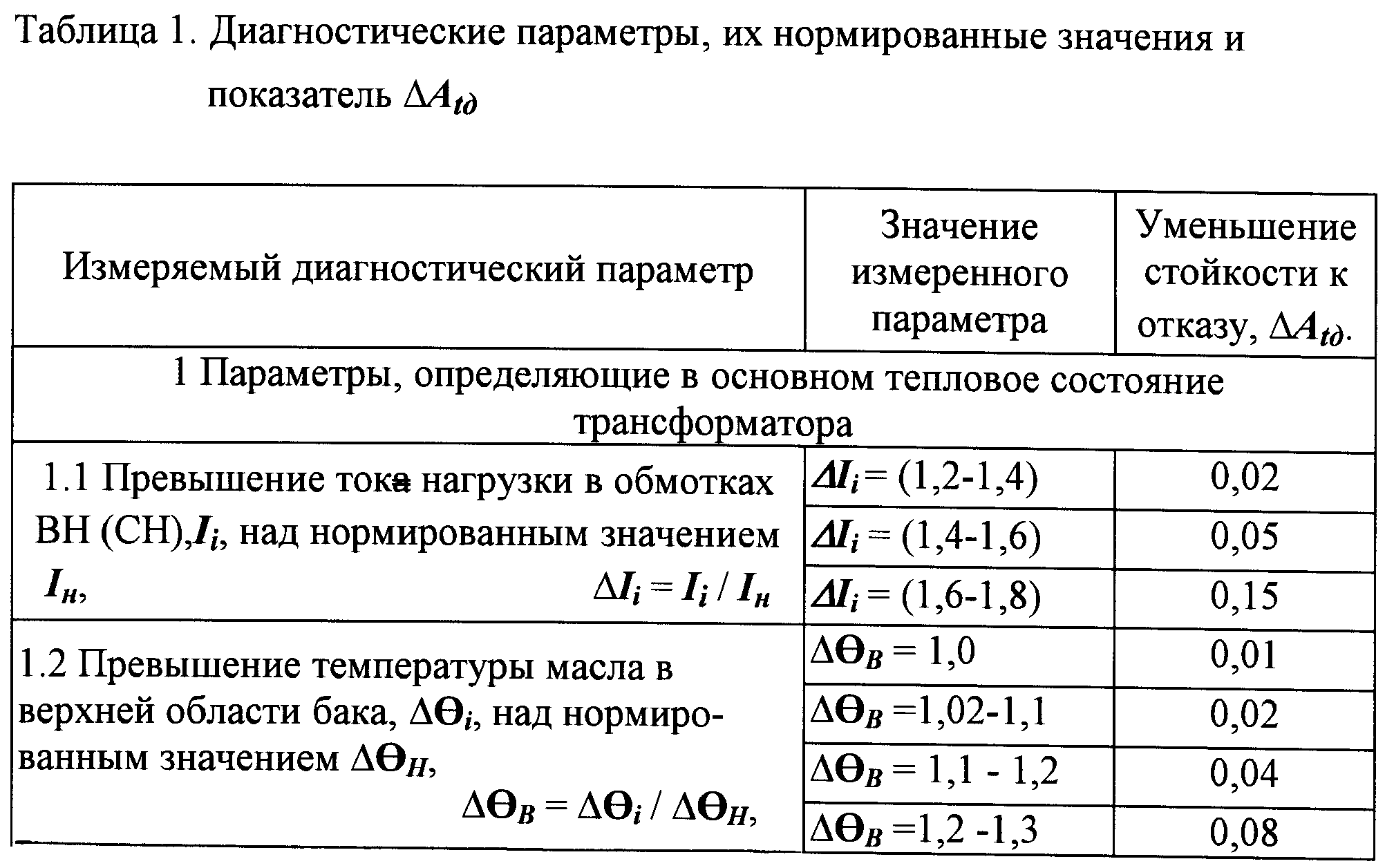
Значение показателя ΔА, характеризующего степень снижения относительной стойкости к отказу, определяется из приведенных значений в табл.1 и зависит от видов и количественных значений диагностических параметров трансформатора.The value of the indicator ΔA, characterizing the degree of decrease in the relative resistance to failure, is determined from the values given in Table 1 and depends on the types and quantitative values of the diagnostic parameters of the transformer.
Дефекты могут приводить к необратимым процессам в старении (ухудшении свойств объекта). К таким дефектам могут относиться:Defects can lead to irreversible processes in aging (deterioration of the properties of the object). Such defects may include:
- «пожар» в стали магнитопровода или образование замкнутого контура;- “fire” in the steel of the magnetic circuit or the formation of a closed loop;
- высокий уровень ЧР и незатухающий процесс ЧР;- high level of PD and continuous process of PD;
- высокий уровень тангенса угла диэлектрических потерь (tgб) в изоляции вводов;- a high level of dielectric loss tangent (tgb) in the insulation of the bushings;
- превышение нормированного числа переключений ответвлений обмотки с помощью регулятора переключения напряжения (РПН),- excess of the normalized number of switching branches of the winding using the voltage switching regulator (on-load tap-changer),
- неправильная работа РПН;- Incorrect operation of the on-load tap-changer;
- неудовлетворительная работа охладителей и др.- unsatisfactory operation of coolers, etc.
Такие дефекты либо вообще не устраняются и тогда сохраняется неизменность оценки ΔА, либо требуют вывода трансформатора в ремонт и после устранения дефекта оценка ΔА изменяется (уменьшается до минимальных значений или до «0»).Such defects are either not eliminated at all and then the ΔА assessment remains unchanged, or they require the transformer to be repaired for repair, and after the defect is eliminated, the ΔА assessment changes (decreases to the minimum values or to "0").
В то же время могут образовываться дефекты, которые устраняются в процессе эксплуатации трансформатора. К таким дефектам могут относиться:At the same time, defects may form which are eliminated during the operation of the transformer. Such defects may include:
- отказ одного или нескольких вентиляторов охладителей (с последующей заменой вентиляторов);- failure of one or more cooler fans (with subsequent replacement of fans);
- снижение уровня масла в баке трансформатора (с последующей дозаливкой масла и устранением течи);- reduction of the oil level in the transformer tank (with subsequent oil replenishment and elimination of the leak);
- изменение давления во вводах относительно нормированного уровня (с последующей установкой соответствующего уровня давления) и др.- change in pressure in the inputs relative to the normalized level (with subsequent installation of the corresponding pressure level), etc.
В последних случаях после устранения дефектов значение соответствующего показателя ΔА может быть принято равным «0».In the latter cases, after elimination of defects, the value of the corresponding indicator ΔА can be taken equal to "0".
На фиг.2 представлена зависимость относительной стойкости трансформатора к отказу при воздействии эксплуатационных факторов и образовании неустраняемых и частично устраняемых дефектов. Используя значения ΔА, время образования дефекта tдеф и закономерности изменения во времени относительной стойкости к отказу, определяют время прогнозируемого отказа tотк=t1, t2, t3 соответственно для случая образования дефектов, не имеющих диагностические параметры, достигающие или превышающие нормированные значения, а также в моменты (tдеф1-tдеф2) и tдеф3.Figure 2 presents the dependence of the relative resistance of the transformer to failure when exposed to operational factors and the formation of unrecoverable and partially eliminated defects. Using the values of ΔА, the defect formation time t def and the patterns of change in time relative failure resistance, determine the predicted failure time t open = t 1 , t 2 , t 3, respectively, for the formation of defects that do not have diagnostic parameters that reach or exceed normalized values , as well as at the moments (t def1 -t def2 ) and t def3 .
На основании полученного прогнозируемого срока службы определяют остаточный ресурс.Based on the obtained predicted service life, the residual life is determined.
В этом случае остаточный ресурс Δtресурс будет равенIn this case, the residual resource Δt resource will be equal to
![]()
![]()
где tдеф - время возникновения дефектов, обнаруженных системой мониторинга, значения диагностических параметров которых превысили нормативные.where t def is the time of occurrence of defects detected by the monitoring system, the values of the diagnostic parameters of which exceeded the standard.
В таблице 1 приведены диагностические параметры, их нормированные значения и показатели снижения остаточного ресурса силовых трансформаторов и приведен пример оценки остаточного ресурса силового трансформатора автотрансформатора АОДЦТГ-167000/500/220.Table 1 shows the diagnostic parameters, their normalized values and indicators for reducing the residual life of power transformers and provides an example of assessing the residual life of a power transformer of autotransformer AODTsTG-167000/500/220.


При использовании показателей ΔАt∂ требуется учитывать суммарное значение группы диагностических параметров показателей ∑ΔAt∂ основных видов дефектов:When using indicators ΔA t∂, it is required to take into account the total value of the group of diagnostic parameters of indicators ∑ΔA t∂ of the main types of defects:
группа 1 - старение электрической изоляции;group 1 - aging of electrical insulation;
группа 2 - локальные быстроразвивающиеся дефекты в изоляции трансформатора;group 2 - local rapidly developing defects in the insulation of the transformer;
группа 3 - интенсивные термические процессы в обмотках и магнитопроводе;group 3 - intense thermal processes in the windings and the magnetic circuit;
группа 4 - низкая эффективность охладителей;group 4 - low efficiency of coolers;
группа 5 - дефектность РПН;group 5 - RPN defectiveness;
группа 6 - дефектность вводов.group 6 - defective inputs.
Группа 1 - (показатель ΔAt∂.1) относится к старению электрической изоляции трансформатора и характеризуется в основном диагностическими параметрами 1.2; 1.3; 1.5; 1,6; 2.3; 2.6; 2,9.Group 1 - (indicator ΔA t∂.1 ) refers to the aging of the electrical insulation of the transformer and is characterized mainly by diagnostic parameters 1.2; 1.3; 1.5; 1.6; 2.3; 2.6; 2.9.
Группа 2 - (показатель ΔAt∂.2) относится к локальным быстроразвивающимся дефектам в электрической изоляции трансформатора и характеризуется в основном диагностическими параметрами 1.2; 1.3; 2.1; 2,2; 2.3-2.4; 2.6; 2,9; 3,2.Group 2 - (indicator ΔA t∂.2 ) refers to local rapidly developing defects in the electrical insulation of the transformer and is characterized mainly by diagnostic parameters 1.2; 1.3; 2.1; 2.2; 2.3-2.4; 2.6; 2.9; 3.2.
Группа 3 - (показатель ΔАt∂.3) относится к интенсивным термическим процессам в обмотках и магнитопроводе и характеризуется в основном диагностическими параметрами 1.1; 1.2; 1.3; 1,4; 1,5; 1,6; 2,9.Group 3 - (indicator ΔА t∂.3 ) refers to intense thermal processes in the windings and magnetic circuit and is characterized mainly by diagnostic parameters 1.1; 1.2; 1.3; 1.4; 1.5; 1.6; 2.9.
Группа 4 - (показатель ΔAt∂.4) относится к низкой эффективности охладителей и характеризуется в основном диагностическими параметрами 1,1; 1,4; 3,3; 3,4; 3,5; 3,6.Group 4 - (indicator ΔA t∂.4 ) refers to the low efficiency of coolers and is characterized mainly by diagnostic parameters 1.1; 1.4; 3.3; 3.4; 3.5; 3.6.
Группа 5 - (показатель ΔAt∂.5) относится к дефектности РПН и характеризуется в основном диагностическими параметрами 3.1, 3.7, 3.8.Group 5 - (indicator ΔA t∂.5 ) refers to the on-load tap-changer and is mainly characterized by diagnostic parameters 3.1, 3.7, 3.8.
Группа 6 - (показатель ΔAt∂.6) относится к дефектности вводов и характеризуется в основном диагностическими параметрами 1.2; 1,6; 2,1; 2.4; 2.5; 2,7; 2,8; 2,9.Group 6 - (indicator ΔA t∂.6 ) refers to defective inputs and is characterized mainly by diagnostic parameters 1.2; 1.6; 2.1; 2.4; 2.5; 2.7; 2.8; 2.9.
Пример оценки остаточного ресурса силового трансформатора Автотрансформатор АОДЦТГ-167 000/500/220.An example of assessing the residual life of a power transformer Autotransformer AODTsTG-167 000/500/220.
Расчетный срок службы - 25 лет; коэффициент М, уточняющий принятое время ресурса 25 лет, М=0,435; α=-0,033.Estimated service life - 25 years; coefficient M, specifying the accepted resource time of 25 years, M = 0.435; α = -0.033.
После 5 лет эксплуатации системой мониторинга установлено превышение отдельных нормативных (диагностических) параметров (см. таблицу 1):After 5 years of operation, the monitoring system established the excess of individual regulatory (diagnostic) parameters (see table 1):
1) превышение тока нагрузки ΔIi=1,4-1,6;1) excess current load ΔI i = 1.4-1.6;
2) превышение температуры масла в верхней области бака ΔΘH=1,2;2) excess of oil temperature in the upper region of the tank ΔΘ H = 1.2;
3) температура окружающего воздуха T0B=30°С;3) ambient temperature T 0B = 30 ° C;
4) время действия перегрева toi=5.102 суток;4) the effect of overheating t oi = 5.10 2 days;
5) превышение показателя газосодержания в масле ПАРГi=1,2;5) the excess of the gas content in the oil P ARGi = 1,2;
6) превышение влагосодержания в масле Δψ=1,1;6) excess moisture content in the oil Δψ = 1,1;
7) разность температуры на входе и выходе охладителя, ΔΘОХ=7°С;7) the temperature difference at the inlet and outlet of the cooler, ΔΘ ОХ = 7 ° С;
8) снижение уровня масла в маслорасширителе бака Δh=0,1;8) a decrease in the oil level in the tank oil conservator Δh = 0.1;
9) превышение кажущегося заряда ЧР Δq=2,0.9) excess of the apparent PD charge Δq = 2.0.
Остаточный ресурс Δtресурс определяется выражениемResidual resource Δt resource is determined by the expression
Δtресурс=tотк-t∂,Δt = t resource TCI -t ∂,
где t∂ - время возникновения дефектов, обнаруженных системой мониторинга, значения диагностических параметров которых превысили нормативные, t∂=5 лет с начала эксплуатации трансформатора;where t ∂ is the time of occurrence of defects detected by the monitoring system, the values of the diagnostic parameters of which exceeded the standard, t ∂ = 5 years from the start of operation of the transformer;
tотк - время ожидаемого отказа, определяемого формулойt TCI - expected time of failure determined by the formula
![]()
![]()
ΔAt∂ определяется как сумма всех значений ΔАt∂i каждого дефекта, который уменьшает относительную стойкость к отказу.ΔA t∂ is defined as the sum of all ΔA t∂i values of each defect, which reduces the relative failure resistance.
![]()
![]()
Индексы 1,…9 относятся к приведенным диагностическим параметрам, достигшим определенных значений ΔAt∂i в соответствии с принятыми данными настоящего примера.
ΔАt∂=0,05+0,04+0,01+0,08+0,02+0,03+0,25+0,1+0,03=0,61.ΔA t∂ = 0.05 + 0.04 + 0.01 + 0.08 + 0.02 + 0.03 + 0.25 + 0.1 + 0.03 = 0.61.
Если не принимать никаких мер по устранению дефектов, приводящих к снижению стойкости к отказу трансформатора, то время наступления ожидаемого отказа tотк после регистрации диагностических параметров системой мониторинга составитIf no action is taken to eliminate the defects, leading to a decrease in the resistance to failure of the transformer, while the occurrence of the expected failure t TCI after registration of diagnostic parameters of the monitoring system will be

В этом случае остаточный ресурс Δtресурс будет равенIn this case, the residual resource Δt resource will be equal to
Δtресурс=tотк-t∂=7,5-5=2,5 года.Δt = t resource OTC -t ∂ = 7,5-5 = 2,5 years.
Некоторые дефекты, приводящие к снижению стойкости к отказу трансформатора, можно устранить. Так, например, можно повысить эффективность работы охладителя за счет ремонта (замены) вентиляторов (ΔAt∂=0,25; п.14 таблицы 1) и, возможно, принять меры по обеспечению герметичности бака (нормального уровня масла в маслорасширителе) (ΔАt∂=0,1; п.3.2 таблицы 1).Some defects that lead to a decrease in transformer failure resistance can be eliminated. So, for example, it is possible to increase the efficiency of the cooler by repairing (replacing) the fans (ΔA t∂ = 0.25; item 14 of table 1) and, possibly, take measures to ensure the tightness of the tank (normal oil level in the conservator) (ΔА t∂ = 0.1; clause 3.2 of table 1).
Тогда ΔAt∂ будет иметь следующее значениеThen ΔA t∂ will have the following value
ΔAt∂=0,61-0,35=0,26ΔA t∂ = 0.61-0.35 = 0.26
и tотк примет следующее значение:t and TCI will take the following meanings:

Следовательно, на момент регистрации диагностических параметров остаточный ресурс Δtресурс будет равенTherefore, at the time of registration of diagnostic parameters Δt resource remaining resource is equal to
Δtресурс=tотк-t∂=16,2-5=11,2 года.Δt = t resource OTC -t ∂ = 16,2-5 = 11,2 years.
Устранение некоторых дефектов может привести к изменению значений отдельных диагностических параметров и соответственно ΔAt∂. Так, например, повышение эффективности работы охладителей приведет к снижению температуры масла в верхней области бака, что также приведет к снижению ΔAt∂i и соответственно в конечном итоге к повышению остаточного ресурса.The elimination of certain defects can lead to a change in the values of individual diagnostic parameters and, accordingly, ΔA t∂ . For example, an increase in the efficiency of the coolers will lead to a decrease in the oil temperature in the upper region of the tank, which will also lead to a decrease in ΔA t∂i and, accordingly, ultimately to an increase in the residual life.
Предлагаемое изобретение может быть применено при техническом обслуживании, периодическом контроле состояния и испытании высоковольтного силового трансформатора с использованием комплекса диагностических параметров. Наиболее эффективно предлагаемое изобретение может быть применено при контроле технического состояния в режиме мониторинга параметров трансформаторов.The present invention can be applied in maintenance, periodic monitoring and testing of a high voltage power transformer using a set of diagnostic parameters. Most effectively, the invention can be applied in monitoring the technical condition in the monitoring mode of the parameters of the transformers.
Источники информацииInformation sources
1. Мурадалиев А.З. Об оценке показателей имитационного моделирования надежности энергооборудования. - Энергетик, №9, 2007 г., стр.27-28.1. Muradaliev A.Z. On the assessment of indicators of simulation modeling of reliability of power equipment. - Power Engineer, No. 9, 2007, pp. 27-28.
2. Кучинский Г.С. Частичные разряды в высоковольтных конструкциях. - Ленинград, «Энергия», Ленинградское отделение, 1979 г., стр.83-86.2. Kuchinsky G.S. Partial discharges in high voltage structures. - Leningrad, "Energy", Leningrad Branch, 1979, pp. 83-86.
Claims (1)
Priority Applications (1)
| Application Number | Priority Date | Filing Date | Title |
|---|---|---|---|
| RU2008114105/28A RU2403581C2 (en) | 2008-04-10 | 2008-04-10 | Method for determination of remaining resource of high-voltage equipment within operating action complex |
Applications Claiming Priority (1)
| Application Number | Priority Date | Filing Date | Title |
|---|---|---|---|
| RU2008114105/28A RU2403581C2 (en) | 2008-04-10 | 2008-04-10 | Method for determination of remaining resource of high-voltage equipment within operating action complex |
Publications (2)
| Publication Number | Publication Date |
|---|---|
| RU2008114105A RU2008114105A (en) | 2009-10-20 |
| RU2403581C2 true RU2403581C2 (en) | 2010-11-10 |
Family
ID=41262550
Family Applications (1)
| Application Number | Title | Priority Date | Filing Date |
|---|---|---|---|
| RU2008114105/28A RU2403581C2 (en) | 2008-04-10 | 2008-04-10 | Method for determination of remaining resource of high-voltage equipment within operating action complex |
Country Status (1)
| Country | Link |
|---|---|
| RU (1) | RU2403581C2 (en) |
Cited By (3)
| Publication number | Priority date | Publication date | Assignee | Title |
|---|---|---|---|---|
| RU2484486C2 (en) * | 2011-08-26 | 2013-06-10 | Общество с ограниченной ответственностью "АРГО-ЦЕНТР" | Diagnostics method of technical state of power equipment |
| RU2540048C2 (en) * | 2013-05-30 | 2015-01-27 | Открытое Акционерное Общество "Российские Железные Дороги" | Electric circuits control method for direct- and alternating-current locomotives |
| RU2556299C1 (en) * | 2014-02-04 | 2015-07-10 | Федеральное государственное бюджетное образовательное учреждение высшего профессионального образования "Алтайский государственный технический университет им. И.И. Ползунова" (АлтГТУ) | Method of determination of remaining life of electric wiring |
-
2008
- 2008-04-10 RU RU2008114105/28A patent/RU2403581C2/en not_active IP Right Cessation
Cited By (3)
| Publication number | Priority date | Publication date | Assignee | Title |
|---|---|---|---|---|
| RU2484486C2 (en) * | 2011-08-26 | 2013-06-10 | Общество с ограниченной ответственностью "АРГО-ЦЕНТР" | Diagnostics method of technical state of power equipment |
| RU2540048C2 (en) * | 2013-05-30 | 2015-01-27 | Открытое Акционерное Общество "Российские Железные Дороги" | Electric circuits control method for direct- and alternating-current locomotives |
| RU2556299C1 (en) * | 2014-02-04 | 2015-07-10 | Федеральное государственное бюджетное образовательное учреждение высшего профессионального образования "Алтайский государственный технический университет им. И.И. Ползунова" (АлтГТУ) | Method of determination of remaining life of electric wiring |
Also Published As
| Publication number | Publication date |
|---|---|
| RU2008114105A (en) | 2009-10-20 |
Similar Documents
| Publication | Publication Date | Title |
|---|---|---|
| DK3061107T3 (en) | Method, system and unit for determining a reduction of residual operating life of an electrical device during a specific operating period of the electrical device | |
| US6446027B1 (en) | Intelligent analysis system and method for fluid-filled electrical equipment | |
| CN107330286A (en) | A kind of large oil immersed power transformer reliability assessment dynamic correcting method | |
| JP4703519B2 (en) | Remaining life diagnosis device for power transformers | |
| JP5973716B2 (en) | Method and system for monitoring transformer health | |
| Wouters et al. | Remaining lifetime modeling of power transformers: individual assets and fleets | |
| EP1085635A2 (en) | Fluid-filled electrical equipment intelligent analysis system and method | |
| Guo et al. | Health index for power transformer condition assessment based on operation history and test data | |
| Susa et al. | Temperature rises in an OFAF transformer at OFAN cooling mode in service | |
| Chantola et al. | Integrated fuzzy logic approach for calculation of health index of power transformer | |
| RU2403581C2 (en) | Method for determination of remaining resource of high-voltage equipment within operating action complex | |
| CN116539759A (en) | Accelerated degradation test method and device for insulating oil dissolved gas on-line monitoring equipment | |
| JP6689212B2 (en) | Life estimation device for pole transformer | |
| JP2009168571A (en) | Method for diagnosing degradation of oil-immersed transformer | |
| Ghazali et al. | TNB experience in condition assessment and life management of distribution power transformers | |
| JP2006060134A (en) | Apparatus and method for assessing the remaining life of transformer for power supply | |
| CN115792461A (en) | Transformer state maintenance method and device with reliability as center | |
| Agarwal et al. | Diagnostic and prognostic models for generator step-up transformers | |
| Farhan Naeem et al. | A novel method for life estimation of power transformers using fuzzy logic systems: An intelligent predictive maintenance approach | |
| Franzén et al. | State of the art-life time modeling and management of transformers | |
| Agarwal et al. | Implementation of remaining useful lifetime transformer models in the fleet-wide prognostic and health management suite | |
| Poiss et al. | Development of indicators for technical condition indexing of power transformers | |
| Sudrajad et al. | Prediction Health Index Using Machine Learning and Its Correlation with Transformer Age on Historical Data | |
| CN117196568A (en) | Operation and maintenance management method for converter station equipment | |
| Cheng et al. | Lifetime assessment and optimized maintenance system of transformers based on the HST model |
Legal Events
| Date | Code | Title | Description |
|---|---|---|---|
| MM4A | The patent is invalid due to non-payment of fees |
Effective date: 20120411 |