RU2399503C2 - Pneumatic suspension - Google Patents
Pneumatic suspension Download PDFInfo
- Publication number
- RU2399503C2 RU2399503C2 RU2008119892/11A RU2008119892A RU2399503C2 RU 2399503 C2 RU2399503 C2 RU 2399503C2 RU 2008119892/11 A RU2008119892/11 A RU 2008119892/11A RU 2008119892 A RU2008119892 A RU 2008119892A RU 2399503 C2 RU2399503 C2 RU 2399503C2
- Authority
- RU
- Russia
- Prior art keywords
- flexible element
- plunger
- elastic element
- atmosphere
- piston
- Prior art date
Links
- 239000000725 suspension Substances 0.000 title claims abstract description 32
- 230000006835 compression Effects 0.000 claims abstract description 14
- 238000007906 compression Methods 0.000 claims abstract description 14
- 238000013016 damping Methods 0.000 abstract description 15
- 230000000694 effects Effects 0.000 abstract 1
- 239000000126 substance Substances 0.000 abstract 1
- 230000033228 biological regulation Effects 0.000 description 5
- 238000005192 partition Methods 0.000 description 3
- 230000005484 gravity Effects 0.000 description 2
- 230000010355 oscillation Effects 0.000 description 2
- 230000003068 static effect Effects 0.000 description 2
- 230000001133 acceleration Effects 0.000 description 1
- 238000009825 accumulation Methods 0.000 description 1
- 238000004891 communication Methods 0.000 description 1
- 230000006866 deterioration Effects 0.000 description 1
- 239000011521 glass Substances 0.000 description 1
- 238000010438 heat treatment Methods 0.000 description 1
- 238000000034 method Methods 0.000 description 1
- 238000005381 potential energy Methods 0.000 description 1
- 238000011084 recovery Methods 0.000 description 1
Images
Landscapes
- Vehicle Body Suspensions (AREA)
- Fluid-Damping Devices (AREA)
Abstract
Description
Изобретение относится к области машиностроения, в частности к амортизационным устройствам для гашения вертикальных колебаний транспортных средств с использованием газа в камере с эластичной стенкой.The invention relates to the field of engineering, in particular to shock-absorbing devices for damping vertical vibrations of vehicles using gas in a chamber with an elastic wall.
Известно устройство для осуществления гашения вертикальных колебаний транспортных средств (а.с. №261926, М. кл. B60G 11/26), содержащее резинокордную оболочку с крышкой, дополнительную емкость, расположенную между ними перегородку с калиброванными отверстиями и клапанное устройство в виде свободно висящей на перегородке диафрагмы, перекрывающей перепускные отверстия на ходе отбоя.A device for damping vertical oscillations of vehicles (a.s. No. 261926, M. class B60G 11/26), containing a rubber-cord shell with a lid, an additional capacity, a partition located between them with calibrated holes and a valve device in the form of a free-hanging on the diaphragm septum overlapping the bypass holes during rebound.
К основным недостаткам устройства относится то, что при вынужденных колебаниях амортизированного объекта с большими амплитудами происходит смещение его среднего положения вниз относительно исходного вследствие постоянного аккумулирования энергии сжатого газа в дополнительной емкости в начале каждого хода сжатия, что приводит к уменьшению динамического хода подвески и снижению эффективности гашения колебаний.The main disadvantages of the device include the fact that during forced oscillations of a shock-absorbed object with large amplitudes, its average position shifts down relative to the original one due to the constant accumulation of compressed gas energy in an additional tank at the beginning of each compression stroke, which leads to a decrease in the suspension's dynamic stroke and a decrease in the damping efficiency fluctuations.
Известно также устройство пневматической подвески (а.с. №968536, М. кл. F16F 9/04 - прототип), содержащее резинокордную оболочку с крышкой, образующие основную рабочую полость, дополнительную емкость, установленную соосно и внутри основной рабочей полости, расположенную между ними перегородку, на которой жестко закреплено клапанное цилиндрическое устройство со штоком. В перегородке расположены калиброванное отверстие и предохранительный клапан для перетекания газа в процессе работы. Основной и дополнительный упругие элементы пневматической подвески установлены между подрессоренной и неподрессоренной массами амортизируемого объекта.Also known is a pneumatic suspension device (AS No. 968536, M. class. F16F 9/04 - prototype) containing a rubber-cord casing with a lid forming the main working cavity, an additional container mounted coaxially and inside the main working cavity, located between them a partition on which a valve cylindrical device with a rod is rigidly fixed. In the partition there is a calibrated hole and a safety valve for gas overflow during operation. The main and additional elastic elements of the air suspension are installed between the sprung and unsprung masses of the depreciable object.
Основным недостатком данного устройства является нестабильность упругих свойств подвески и низкая эффективность гашения колебаний из-за того, что в гашении колебаний и в создании упругой составляющей подвески участвует постоянная масса газа (воздуха), часть которой то отводится в начале хода отбоя, то возвращается на ходе сжатия. Такое перетекание из основного упругого элемента подвески в дополнительный и наоборот приводит к нагреву рабочей среды подвески, что ведет к изменению термодинамических параметров, а следовательно, к ухудшению упругих и демпфирующих свойств подвески. Недостатком данного устройства является также то, что пневматический упругий элемент не обеспечивает регулирование упругодемпфирующей характеристики при воздействии любых внешних сил переменной частоты и амплитуды.The main disadvantage of this device is the instability of the elastic properties of the suspension and the low damping efficiency due to the fact that a constant mass of gas (air) is involved in the damping of the vibrations and in creating the elastic component of the suspension, some of which is discharged at the beginning of the rebound stroke, then returns during compression. Such a flow from the main elastic element of the suspension to the additional one and vice versa leads to heating of the working medium of the suspension, which leads to a change in the thermodynamic parameters and, consequently, to a deterioration in the elastic and damping properties of the suspension. The disadvantage of this device is that the pneumatic elastic element does not provide regulation of the elastic-damping characteristics when exposed to any external forces of variable frequency and amplitude.
Задачей предлагаемого изобретения является повышение упругих свойств пневматической подвески и обеспечение регулирования ее упругодемпфирующих характеристик во всем амплитудно-частотном диапазоне внешнего воздействия.The task of the invention is to increase the elastic properties of the air suspension and to ensure the regulation of its elastic-damping characteristics in the entire amplitude-frequency range of external influence.
Поставленная задача достигается тем, что в пневматической подвеске, содержащей установленный между подрессоренной и неподрессоренной массами основной упругий элемент и соосно установленный внутри него дополнительный упругий элемент, согласно изобретению дополнительный упругий элемент выполнен в виде полого плунжера, который разделен поршнем на две полости, при этом нижняя полость плунжера соединена воздушным каналом через электропневмоклапан, в цепи питания которого расположено коммутирующее устройство, соединенное с датчиком скорости, для подвода массы газа в начале каждого хода сжатия - с ресивером, а для отвода этой массы газа в начале каждого хода отбоя - с атмосферой, а верхняя полость плунжера через осевые и радиальные отверстия в штоке поршня также соединена с атмосферой, причем шток поршня укреплен в крышке основного упругого элемента.The problem is achieved in that in the air suspension containing the main elastic element installed between the sprung and unsprung masses and the additional elastic element coaxially mounted inside it, according to the invention, the additional elastic element is made in the form of a hollow plunger, which is divided into two cavities by the piston, while the lower the cavity of the plunger is connected by an air channel through an electro-pneumatic valve, in the power circuit of which is located a switching device connected to the sensor growth, for supplying the mass of gas at the beginning of each compression stroke - with the receiver, and for the removal of this gas mass at the beginning of each rebound stroke - with the atmosphere, and the upper cavity of the plunger through axial and radial holes in the piston rod is also connected to the atmosphere, and the piston rod fixed in the cover of the main elastic element.
Существенным отличием предложенной пневматической подвески является то, что увеличение упругой силы основного упругого элемента на ходе сжатия осуществляется не за счет отсечки части массы газа из дополнительного упругого элемента в основной, как это осуществляется в известной пневматической подвеске, а за счет подвода дополнительной массы газа под давлением из автономного источника энергии в нижнюю полость дополнительного упругого элемента в фазе движения объекта, что приводит к резкому увеличению потенциальной энергии системы в начале хода сжатия, а значит и в период всего хода сжатия.A significant difference of the proposed air suspension is that the increase in the elastic force of the main elastic element during compression is not due to cutting off part of the mass of gas from the additional elastic element to the main one, as is done in the known air suspension, but by supplying an additional mass of gas under pressure from an autonomous energy source into the lower cavity of the additional elastic element in the phase of the object’s movement, which leads to a sharp increase in the potential energy of the system in n at the beginning of the compression stroke, and therefore during the entire compression stroke.
Кроме того, предлагаемая пневматическая подвеска обеспечивает широкое регулирование упругодемпфирующей характеристики за счет уменьшения или увеличения подводимого давления от автономного источника энергии в фазе движения объекта.In addition, the proposed air suspension provides wide regulation of the elastic-damping characteristics by reducing or increasing the input pressure from an autonomous energy source in the phase of movement of the object.
Сущность изобретения поясняется чертежами, гдеThe invention is illustrated by drawings, where
- на фиг.1 представлена предложенная пневматическая подвеска;- figure 1 presents the proposed air suspension;
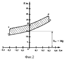
- на фиг.2 приведены упругодемпфирующие характеристики пневматической подвески.- figure 2 shows the elastic damping characteristics of the air suspension.
Пневматическая подвеска содержит резинокордную оболочку 1, расположенную в стакане 2 с крышкой 3 и внутренний полый плунжер 4, которые образуют переменную полость «А». При этом внутренний полый плунжер 4 выполнен в виде цилиндра и разделен поршнем 5 на две полости: нижнюю полость «В» и верхнюю полость «С». Шток 6 поршня 5 жестко закреплен на крышке 3 упругого элемента.The air suspension contains a rubber-cord casing 1 located in a glass 2 with a cover 3 and an internal hollow plunger 4, which form a variable cavity "A". The internal hollow plunger 4 is made in the form of a cylinder and is divided by a
Нижняя полость «В» расположена с возможностью соединения через гибкий трубопровод 7 и электропневмоклапан (ЭПК) 8 или с ресивером 9 транспортного средства, или с атмосферой.The lower cavity "B" is located with the possibility of connection through a flexible conduit 7 and an electro-pneumatic valve (EPC) 8 or with the receiver 9 of the vehicle, or with the atmosphere.
Верхняя полость «С» постоянно сообщается через осевое отверстие 10 и радиальные отверстия 11 в штоке 6 поршня 5 с атмосферой, при этом никакого сопротивления при протекании воздуха из полости «С» в атмосферу или обратно не создается.The upper cavity "C" is constantly in communication through the
Для подвода массы газа из ресивера 9 в полость «В» в начале каждого хода сжатия и отвода этой массы газа в начале каждого хода отбоя в атмосферу предназначен ЭПК 8.To supply the mass of gas from the receiver 9 to the cavity "B" at the beginning of each compression stroke and the removal of this mass of gas at the beginning of each rebound stroke into the atmosphere is designed EPA 8.
Управление ЭПК 8 производится датчиком относительной скорости 12 внешнего стакана 2, выход которого соединен с коммутирующим устройством 13, расположенным в цепи питания ЭПК 8.EPK 8 is controlled by a relative speed sensor 12 of the outer cup 2, the output of which is connected to a switching device 13 located in the EPA 8 power supply circuit.
Предлагаемая пневматическая подвеска работает следующим образом.The proposed air suspension works as follows.
В статическом положении пневматической подвески сила тяжести подрессоренной массы уравновешивается только за счет избыточного давления в полости «А», т.е.In the static position of the air suspension, the gravity of the sprung mass is balanced only due to the excess pressure in the cavity "A", i.e.
M*g=P10*S1,M * g = P10 * S1,
где М - масса амортизируемого объекта;where M is the mass of the depreciable object;
Р10 - давление в полости «А» в статическом положении пневматической подвески;P10 - pressure in the cavity "A" in the static position of the air suspension;
S1 - эффективная площадь пневматической подвески;S1 is the effective area of the air suspension;
g - ускорение свободного падения.g is the acceleration of gravity.
На ходе сжатия пневматической подвески давление газа в полости «А» возрастает, в полости «С» остается равным атмосферному. В начале хода сжатия от датчика относительной скорости 12 подается сигнал на коммутирующее устройство 13, которое соединяет ЭПК 8 с источником питания, и последний, включаясь, сообщает полость «В» через трубопровод 7 с ресивером 9.During compression of the air suspension, the gas pressure in the cavity "A" increases, in the cavity "C" remains equal to atmospheric. At the beginning of the compression stroke from the relative velocity sensor 12, a signal is supplied to the switching device 13, which connects the EPA 8 to the power source, and the latter, when turned on, reports the cavity "B" through the pipe 7 to the receiver 9.
Подвод массы газа в нижнюю полость «В» под давлением Р2≤Р1 оказывает существенное содействие основному упругому элементу и приводит к резкому увеличению упругой силы пневматической подвески на величину P2*S2, т.е. упругая сила пневматической подвески:The supply of gas mass to the lower cavity "B" under pressure P2≤P1 significantly contributes to the main elastic element and leads to a sharp increase in the elastic force of the air suspension by the amount of P2 * S2, i.e. air suspension elastic force:
Pynp=P1*S1+P2*S2,Pynp = P1 * S1 + P2 * S2,
где Р1 - текущее давление в полости «А»;where P1 is the current pressure in the cavity "A";
Р2 - текущее давление в нижней полости «В»;P2 - current pressure in the lower cavity "B";
S2 - эффективная площадь в нижней полости.S2 is the effective area in the lower cavity.
Таким образом, давление Р2 содействует давлению Р1. В начале очередного хода отбоя ЭПК 8 обесточивается и полость «В» через ЭПК 8 сообщается с атмосферой, что приводит к восстановлению упругой силы пневматической подвески:Thus, the pressure P2 contributes to the pressure P1. At the beginning of the next rebound stroke, EPK 8 is de-energized and cavity “B” communicates with the atmosphere through EPK 8, which leads to the restoration of the elastic force of the air suspension:
Pynp=P1*S1.Pynp = P1 * S1.
На фиг.2 представлены упругодемпфирующие характеристики пневматической подвески. Участок «а-b» характеристики соответствует работе только основного упругого элемента 3 при ходе отбоя и ходе сжатия без включения в работу нижней полости «В», участок «a-c-d-b» соответствует совместной работе основного упругого элемента 3 и нижней полости «В» при ходе сжатия.Figure 2 presents the elastic damping characteristics of the air suspension. Section “a-b” of the characteristic corresponds only to the operation of the main elastic element 3 during the rebound and compression without turning on the lower cavity “B”, the section “acdb” corresponds to the joint operation of the main elastic element 3 and the lower cavity “B” during compression .
Также пневматическая подвеска, реализующая предложенный способ гашения вертикальных колебаний объектов, обеспечивает широкое регулирование упругодемпфирующей характеристики за счет уменьшения или увеличения подводимого давления Р2 в нижнюю полость «В», т.е. предлагаемая пневматическая подвеска обеспечивает регулирование упругодемпфирующей характеристики во всем амплитудно-частотном диапазоне внешнего воздействия.Also, a pneumatic suspension that implements the proposed method of damping vertical vibrations of objects, provides wide regulation of the elastic-damping characteristics by reducing or increasing the input pressure P2 into the lower cavity "B", i.e. the proposed air suspension provides regulation of the elastic-damping characteristics in the entire amplitude-frequency range of the external influence.
Таким образом, увеличение упругой силы пневматической подвески в начале каждого хода сжатия за счет подвода из автономного источника дополнительной энергии в полость дополнительного упругого элемента в фазе движения объекта и быстрое восстановление ее в начале каждого хода отбоя приводит к увеличению жесткости пневматической подвески, что повышает безопасность движения транспортного средства при движении с большой скоростью по ровным дорогам, снижает крен транспортного средства при поворотах, оседание при трогании с места, переключении передач и торможении, способствует повышению комфортабельности экипажа при движении транспортного средства.Thus, the increase in the elastic force of the air suspension at the beginning of each compression stroke due to the supply of additional energy from the autonomous source to the cavity of the additional elastic element in the phase of the object’s movement and its quick recovery at the beginning of each rebound stroke leads to an increase in the stiffness of the air suspension, which increases traffic safety the vehicle when driving at high speed on flat roads, reduces the roll of the vehicle when cornering, settling when moving away, shifting gears and braking, improves crew comfort when driving a vehicle.
Claims (1)
Priority Applications (1)
| Application Number | Priority Date | Filing Date | Title |
|---|---|---|---|
| RU2008119892/11A RU2399503C2 (en) | 2008-05-19 | 2008-05-19 | Pneumatic suspension |
Applications Claiming Priority (1)
| Application Number | Priority Date | Filing Date | Title |
|---|---|---|---|
| RU2008119892/11A RU2399503C2 (en) | 2008-05-19 | 2008-05-19 | Pneumatic suspension |
Publications (2)
| Publication Number | Publication Date |
|---|---|
| RU2008119892A RU2008119892A (en) | 2009-11-27 |
| RU2399503C2 true RU2399503C2 (en) | 2010-09-20 |
Family
ID=41476236
Family Applications (1)
| Application Number | Title | Priority Date | Filing Date |
|---|---|---|---|
| RU2008119892/11A RU2399503C2 (en) | 2008-05-19 | 2008-05-19 | Pneumatic suspension |
Country Status (1)
| Country | Link |
|---|---|
| RU (1) | RU2399503C2 (en) |
Citations (3)
| Publication number | Priority date | Publication date | Assignee | Title |
|---|---|---|---|---|
| US2056106A (en) * | 1935-07-24 | 1936-09-29 | John W Kuhn | Pneumatic spring |
| EP1429045A2 (en) * | 2002-12-11 | 2004-06-16 | Phoenix AG | Air spring arrangement |
| RU2304523C1 (en) * | 2006-03-29 | 2007-08-20 | Государственное Образовательное Учреждение Высшего Профессионального Образования "Омский Государственный Технический Университет" | Pneumatic suspension |
-
2008
- 2008-05-19 RU RU2008119892/11A patent/RU2399503C2/en not_active IP Right Cessation
Patent Citations (3)
| Publication number | Priority date | Publication date | Assignee | Title |
|---|---|---|---|---|
| US2056106A (en) * | 1935-07-24 | 1936-09-29 | John W Kuhn | Pneumatic spring |
| EP1429045A2 (en) * | 2002-12-11 | 2004-06-16 | Phoenix AG | Air spring arrangement |
| RU2304523C1 (en) * | 2006-03-29 | 2007-08-20 | Государственное Образовательное Учреждение Высшего Профессионального Образования "Омский Государственный Технический Университет" | Pneumatic suspension |
Also Published As
| Publication number | Publication date |
|---|---|
| RU2008119892A (en) | 2009-11-27 |
Similar Documents
| Publication | Publication Date | Title |
|---|---|---|
| CN104514833B (en) | For the spring cushion system in load-bearing part or as damper | |
| KR101218834B1 (en) | Body amplitude sensitive air spring | |
| CN103935206B (en) | Spring vibration damper with helical spring element and rubber buffer element | |
| CN105235552B (en) | The method of vehicle suspension system and suspension installation vehicle part | |
| JPH0569715A (en) | Car suspension | |
| US20080079280A1 (en) | Vehicle-body supporting apparatus and vehicle-body supporting system | |
| RU2304523C1 (en) | Pneumatic suspension | |
| SE0002453D0 (en) | Pressure dependent reacting valve, especially for a vibration damper | |
| KR102536091B1 (en) | Damper device for vehicle chassis with leveling system | |
| JP2017140930A (en) | Suspension device | |
| CN103775554A (en) | Double-air-bag rigidity stepless adjustable oil-gas spring | |
| RU2399503C2 (en) | Pneumatic suspension | |
| RU193624U1 (en) | Air suspension | |
| CN108026998A (en) | Air spring with multiple damping units | |
| CN109505912A (en) | Half active Frequency Adjustable dynamic vibration absorber and vibration absorption method based on magnetorheological fluid characteristic | |
| RU169805U1 (en) | AIR SUSPENSION | |
| JP2005172173A (en) | Series type engine mount and manufacturing method of series type engine mount | |
| JP5456597B2 (en) | Hydraulic shock absorber | |
| CN216407585U (en) | Nonmetal variable cavity for vibration damper | |
| RU2340468C1 (en) | Pneumatic suspension | |
| RU2399504C2 (en) | Pneumatic suspension | |
| RU2405990C2 (en) | Method for suppression of vertical oscillations of object with pneumatic suspension | |
| RU2424123C2 (en) | Air suspension | |
| RU167265U1 (en) | AIR SUSPENSION | |
| JP5952629B2 (en) | Suspension control device |
Legal Events
| Date | Code | Title | Description |
|---|---|---|---|
| MM4A | The patent is invalid due to non-payment of fees |
Effective date: 20150520 |