RU2395332C1 - Lock for strip - Google Patents

Lock for strip Download PDF

Info

Publication number
RU2395332C1
RU2395332C1 RU2008145496/15A RU2008145496A RU2395332C1 RU 2395332 C1 RU2395332 C1 RU 2395332C1 RU 2008145496/15 A RU2008145496/15 A RU 2008145496/15A RU 2008145496 A RU2008145496 A RU 2008145496A RU 2395332 C1 RU2395332 C1 RU 2395332C1
Authority
RU
Russia
Prior art keywords
strip
gateway according
chamber
gateway
pressure level
Prior art date
Application number
RU2008145496/15A
Other languages
Russian (ru)
Other versions
RU2008145496A (en
Inventor
Лутц КЮММЕЛЬ (DE)
Лутц КЮММЕЛЬ
Андреас ГРАМЕР (DE)
Андреас Грамер
Хольгер БЕРЕНС (DE)
Хольгер Беренс
Маттиас КРЕЧМЕР (DE)
Маттиас Кречмер
Ральф-Хартмут ЗОЛЬ (DE)
Ральф-Хартмут Золь
КОК Петер ДЕ (DE)
КОК Петер ДЕ
Original Assignee
Смс Зимаг Акциенгезелльшафт
Priority date (The priority date is an assumption and is not a legal conclusion. Google has not performed a legal analysis and makes no representation as to the accuracy of the date listed.)
Filing date
Publication date
Application filed by Смс Зимаг Акциенгезелльшафт filed Critical Смс Зимаг Акциенгезелльшафт
Publication of RU2008145496A publication Critical patent/RU2008145496A/en
Application granted granted Critical
Publication of RU2395332C1 publication Critical patent/RU2395332C1/en

Links

Images

Classifications

    • BPERFORMING OPERATIONS; TRANSPORTING
    • B01PHYSICAL OR CHEMICAL PROCESSES OR APPARATUS IN GENERAL
    • B01JCHEMICAL OR PHYSICAL PROCESSES, e.g. CATALYSIS OR COLLOID CHEMISTRY; THEIR RELEVANT APPARATUS
    • B01J3/00Processes of utilising sub-atmospheric or super-atmospheric pressure to effect chemical or physical change of matter; Apparatus therefor
    • B01J3/02Feed or outlet devices therefor
    • BPERFORMING OPERATIONS; TRANSPORTING
    • B01PHYSICAL OR CHEMICAL PROCESSES OR APPARATUS IN GENERAL
    • B01JCHEMICAL OR PHYSICAL PROCESSES, e.g. CATALYSIS OR COLLOID CHEMISTRY; THEIR RELEVANT APPARATUS
    • B01J3/00Processes of utilising sub-atmospheric or super-atmospheric pressure to effect chemical or physical change of matter; Apparatus therefor
    • B01J3/006Processes utilising sub-atmospheric pressure; Apparatus therefor
    • BPERFORMING OPERATIONS; TRANSPORTING
    • B01PHYSICAL OR CHEMICAL PROCESSES OR APPARATUS IN GENERAL
    • B01JCHEMICAL OR PHYSICAL PROCESSES, e.g. CATALYSIS OR COLLOID CHEMISTRY; THEIR RELEVANT APPARATUS
    • B01J3/00Processes of utilising sub-atmospheric or super-atmospheric pressure to effect chemical or physical change of matter; Apparatus therefor
    • B01J3/03Pressure vessels, or vacuum vessels, having closure members or seals specially adapted therefor
    • CCHEMISTRY; METALLURGY
    • C23COATING METALLIC MATERIAL; COATING MATERIAL WITH METALLIC MATERIAL; CHEMICAL SURFACE TREATMENT; DIFFUSION TREATMENT OF METALLIC MATERIAL; COATING BY VACUUM EVAPORATION, BY SPUTTERING, BY ION IMPLANTATION OR BY CHEMICAL VAPOUR DEPOSITION, IN GENERAL; INHIBITING CORROSION OF METALLIC MATERIAL OR INCRUSTATION IN GENERAL
    • C23CCOATING METALLIC MATERIAL; COATING MATERIAL WITH METALLIC MATERIAL; SURFACE TREATMENT OF METALLIC MATERIAL BY DIFFUSION INTO THE SURFACE, BY CHEMICAL CONVERSION OR SUBSTITUTION; COATING BY VACUUM EVAPORATION, BY SPUTTERING, BY ION IMPLANTATION OR BY CHEMICAL VAPOUR DEPOSITION, IN GENERAL
    • C23C16/00Chemical coating by decomposition of gaseous compounds, without leaving reaction products of surface material in the coating, i.e. chemical vapour deposition [CVD] processes
    • FMECHANICAL ENGINEERING; LIGHTING; HEATING; WEAPONS; BLASTING
    • F27FURNACES; KILNS; OVENS; RETORTS
    • F27DDETAILS OR ACCESSORIES OF FURNACES, KILNS, OVENS, OR RETORTS, IN SO FAR AS THEY ARE OF KINDS OCCURRING IN MORE THAN ONE KIND OF FURNACE
    • F27D99/00Subject matter not provided for in other groups of this subclass
    • F27D99/0073Seals
    • BPERFORMING OPERATIONS; TRANSPORTING
    • B01PHYSICAL OR CHEMICAL PROCESSES OR APPARATUS IN GENERAL
    • B01JCHEMICAL OR PHYSICAL PROCESSES, e.g. CATALYSIS OR COLLOID CHEMISTRY; THEIR RELEVANT APPARATUS
    • B01J2219/00Chemical, physical or physico-chemical processes in general; Their relevant apparatus
    • B01J2219/00002Chemical plants
    • B01J2219/00027Process aspects
    • B01J2219/00033Continuous processes
    • FMECHANICAL ENGINEERING; LIGHTING; HEATING; WEAPONS; BLASTING
    • F27FURNACES; KILNS; OVENS; RETORTS
    • F27DDETAILS OR ACCESSORIES OF FURNACES, KILNS, OVENS, OR RETORTS, IN SO FAR AS THEY ARE OF KINDS OCCURRING IN MORE THAN ONE KIND OF FURNACE
    • F27D99/00Subject matter not provided for in other groups of this subclass
    • F27D99/0073Seals
    • F27D2099/0078Means to minimize the leakage of the furnace atmosphere during charging or discharging

Landscapes

  • Chemical & Material Sciences (AREA)
  • Organic Chemistry (AREA)
  • Chemical Kinetics & Catalysis (AREA)
  • Engineering & Computer Science (AREA)
  • Mechanical Engineering (AREA)
  • General Engineering & Computer Science (AREA)
  • General Chemical & Material Sciences (AREA)
  • Materials Engineering (AREA)
  • Metallurgy (AREA)
  • Sealing Devices (AREA)
  • Sliding Valves (AREA)
  • Heat Treatment Of Strip Materials And Filament Materials (AREA)
  • Coating Apparatus (AREA)
  • Gasket Seals (AREA)
  • Physical Vapour Deposition (AREA)
  • Control Of Motors That Do Not Use Commutators (AREA)
  • Package Closures (AREA)
  • Operating, Guiding And Securing Of Roll- Type Closing Members (AREA)
  • Seal Device For Vehicle (AREA)
  • Finger-Pressure Massage (AREA)
  • Advancing Webs (AREA)
  • Bag Frames (AREA)
  • Slide Fasteners (AREA)
  • Sealing Material Composition (AREA)
  • Delivering By Means Of Belts And Rollers (AREA)

Abstract

FIELD: machine building. ^ SUBSTANCE: invention is intended for sealing. Lock for a strip for tightening the first chamber relative to the second chamber; at that, the strip, namely metal strip, passes through both chambers, includes at least one sealing device which includes at least two gate valves movable in relation to each other and having at least one sealing surface fitted on the edge outline of the sealed strip. At least two gate valves are made in the form of plates and located parallel to each other and adjoin each other. ^ EFFECT: good sealing property. ^ 93 cl, 18 dwg

Description

Изобретение относится к шлюзу для полосы для герметизации первой камеры относительно второй камеры, причем полоса, в частности металлическая полоса, проходит через обе камеры, и для герметизации камер предусмотрено, по меньшей мере, одно уплотняющее средство.The invention relates to a gateway for a strip for sealing the first chamber relative to the second chamber, wherein the strip, in particular the metal strip, passes through both chambers, and at least one sealing means is provided for sealing the chambers.

При изготовлении и улучшении металлической полосы, в частности стальной полосы, при случае требуется осуществлять процессы в условиях пониженного давления (вакуумный процесс). Для этого полоса направляется в камеру, которая имеет пониженный относительно окружающего давления уровень давления. Для достижения непрерывного процесса необходимы шлюзы описанного выше рода, которые герметизируют полосу между камерами с разными уровнями давления. Шлюзы служат, следовательно, в первую очередь, для создания разности давлений между двумя зонами обработки полосы.In the manufacture and improvement of a metal strip, in particular a steel strip, it is necessary to carry out processes under reduced pressure (vacuum process). For this, the strip is directed into the chamber, which has a pressure level lower than the ambient pressure. To achieve a continuous process, gateways of the kind described above are needed, which seal the strip between chambers with different pressure levels. The locks are, therefore, primarily for creating a pressure difference between the two processing zones of the strip.

Такие шлюзы известны, например, из DE 4418383 C2 и DE 19960751 А1. В этих публикациях говорится о том, что на одной шлюзовой ступени к полосе для ее герметизации прилегают два герметизирующих ролика, а именно один ролик к верхней, а другой - к нижней стороне полосы.Such gateways are known, for example, from DE 4418383 C2 and DE 19960751 A1. These publications state that at one lock stage two sealing rollers are adjacent to the strip for its sealing, namely one roller to the upper and the other to the lower side of the strip.

Такие шлюзы для полосы используются, как правило, для изделий с отношением ширины к толщине, по существу, более 1. Они могут использоваться также для герметизации друг от друга двух камер, в которых для обработки полосы используются разные среды.Such strip locks are used, as a rule, for products with a ratio of width to thickness substantially greater than 1. They can also be used to seal two chambers from each other, in which different media are used to process the strip.

Из-за требуемой опоры герметизирующих роликов герметизация с их помощью является относительно сложной и, тем самым, дорогостоящей, в частности, когда обусловленная процессом плавки ширина и/или толщина герметизируемой полосы изменяется. Сложным является согласование шлюза с полосами разной ширины и толщины. Настройка частично негативно влияет также на качество герметизации.Due to the required support of the sealing rollers, sealing with them is relatively complex and, therefore, expensive, in particular when the width and / or thickness of the sealing strip due to the smelting process changes. It is difficult to coordinate the gateway with stripes of different widths and thicknesses. The setting also partially affects the quality of the seal.

Поэтому в основе настоящего изобретения лежит задача усовершенствования шлюза описанного выше рода так, чтобы можно было достичь в этом отношении улучшения. Следовательно, шлюз должен обладать улучшенным уплотяющим действием и простым образом настраиваться на полосы разной ширины и толщины.Therefore, the present invention is based on the task of improving the gateway of the kind described above so that improvement can be achieved in this regard. Therefore, the gateway should have an improved sealing effect and be easily tuned to strips of different widths and thicknesses.

Решение этой задачи за счет изобретения характеризуется тем, что уплотняющее средство содержит, по меньшей мере, две подвижные по отношению друг к другу заслонки, имеющие, по меньшей мере, одну уплотняющую поверхность, которая подогнана к краевому контуру герметизируемой полосы.The solution to this problem due to the invention is characterized in that the sealing means comprises at least two flaps movable with respect to each other having at least one sealing surface that is fitted to the edge contour of the sealing strip.

Предпочтительно, по меньшей мере, две заслонки выполнены в виде пластин и расположены параллельно друг другу и с непосредственным контактом друг с другом. При этом отдельные пластинчатые заслонки герметично прилегают друг к другу. По меньшей мере, одна часть заслонок может быть связана с исполнительными элементами для перемещения заслонки в направлении, перпендикулярном направлению транспортировки полосы.Следовательно, согласно изобретению, несколько заслонок подводятся к полосе, образуя для нее проходной канал, соответствующий ее форме. Для этого заслонки имеют, по меньшей мере, одну уплотняющую поверхность, соответствующую форме полосы.Preferably, at least two shutters are made in the form of plates and are parallel to each other and in direct contact with each other. In this case, individual plate shutters are tightly adjacent to each other. At least one part of the shutters may be connected with actuators for moving the shutter in a direction perpendicular to the direction of transportation of the strip. Accordingly, according to the invention, several shutters are brought to the strip, forming for it a passage channel corresponding to its shape. For this, the shutters have at least one sealing surface corresponding to the shape of the strip.

В одном предпочтительном варианте предусмотрено, по меньшей мере, две подвижные по отношению друг к другу заслонки, каждая из которых имеет прямоугольное отверстие для прохождения полосы. Это - при соответствующем смещении заслонок - позволяет создавать любые прямоугольные проходные каналы для полосы.In one preferred embodiment, at least two flaps are movable with respect to each other, each of which has a rectangular opening for the passage of the strip. This - with the appropriate displacement of the dampers - allows you to create any rectangular passage channels for the strip.

В одном альтернативном варианте предусмотрено, по меньшей мере, две подвижные по отношению друг к другу заслонки, каждая из которых имеет две перпендикулярные друг к другу уплотняющие поверхности. Взаимодействуя между собой, эти заслонки также могут образовать прямоугольный проходной канал для полосы, точно соответствующий форме ее поперечного сечения.In one alternative embodiment, at least two flaps are movable with respect to each other, each of which has two sealing surfaces perpendicular to each other. Interacting with each other, these shutters can also form a rectangular passage channel for the strip, exactly corresponding to the shape of its cross section.

В другом альтернативном варианте предусмотрено четыре подвижные по отношению друг к другу заслонки, каждая из которых имеет проходящую прямо уплотняющую поверхность. Следовательно, в общей сложности, четыре заслонки сходятся, образуя прямоугольный проходной канал для полосы.In another alternative, four flaps are movable with respect to each other, each of which has a straight sealing surface extending directly. Consequently, in total, the four dampers converge, forming a rectangular passage channel for the strip.

Одна из заслонок может быть выполнена также в виде ролика.One of the shutters can also be made in the form of a roller.

По меньшей мере, одна из заслонок выполнена с возможностью прижатия к поверхности полосы своей уплотняющей поверхностью посредством по меньшей мере одной пружины.At least one of the shutters is adapted to be pressed against the strip surface by its sealing surface by means of at least one spring.

Для точного направления полосы в одной модификации изобретения предусмотрен, по меньшей мере, один направляющий ролик, который набегает на кромку полосы и направляет полосу относительно шлюза.For the exact direction of the strip in one embodiment of the invention, at least one guide roller is provided that runs on the edge of the strip and directs the strip relative to the lock.

В одном специальном варианте осуществления изобретения, по меньшей мере, одна заслонка оснащена средствами для подгонки рабочей высоты и/или рабочей ширины. При этом предпочтительно предусмотрено, что средства для подгонки рабочей высоты или ширины реализованы двумя частями заслонки, которые прилегают друг к другу срезанными под углом к направлению транспортировки полосы контактными поверхностями; при этом, по меньшей мере, одна из частей заслонки выполнена с возможностью позиционирования в направлении транспортировки полосы посредством элемента перемещения.In one special embodiment of the invention, at least one shutter is equipped with means for adjusting the working height and / or working width. In this case, it is preferably provided that the means for adjusting the working height or width are realized by two parts of the shutter, which abut against each other cut off by contact surfaces at an angle to the direction of transport of the strip; however, at least one of the parts of the shutter is arranged to be positioned in the direction of transportation of the strip by means of a moving element.

Чтобы при износе можно было быстро и просто использовать новую заслонку с новой уплотняющей поверхностью, зарекомендовало себя средство замены, с помощью которого заслонка может вдвигаться в уплотняемую зону или выдвигаться из нее поперек направления транспортировки полосы.In order to quickly and easily use a new damper with a new sealing surface during wear, a means of replacement has proven itself, by means of which the damper can be moved into or out of the sealing area across the strip transport direction.

Для стабилизации полоса может направляться в направлении транспортировки двумя роликами так, что до и после заслонок происходит двойное отклонение полосы.To stabilize, the strip can be guided in the direction of transportation by two rollers so that before and after the shutters there is a double deflection of the strip.

Чтобы создать более высокие разности давлений, зарекомендовало себя расположение друг за другом в направлении движения полосы нескольких шлюзовых ступеней.In order to create higher pressure differences, it has proven itself to be located one after the other in the direction of movement of the strip of several lock stages.

Шлюз предпочтительно используется для герметизации первой камеры с первым уровнем давления относительно второй камеры со вторым уровнем давления, отличающимся от первого уровня давления. Он может использоваться также при равенстве давлений в камерах, когда в них должны быть герметизированы друг от друга разные среды; т.е. в этом случае предусмотрено, что шлюз используется для герметизации первой камеры с первой технологической средой относительно второй камеры со второй технологической средой, отличающейся от первой технологической среды.The lock is preferably used to seal the first chamber with a first pressure level relative to the second chamber with a second pressure level different from the first pressure level. It can also be used in case of equal pressure in the chambers, when different media must be sealed from each other in them; those. in this case, it is provided that the gateway is used to seal the first chamber with the first technological medium relative to the second chamber with the second technological medium different from the first technological medium.

Примеры осуществления изобретения изображены на чертежах, на которых представлено:Examples of the invention are shown in the drawings, on which:

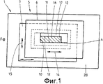
фиг. 1 - существенные части шлюза в направлении транспортировки герметизируемой полосы;FIG. 1 - significant parts of the lock in the direction of transportation of the sealed strip;

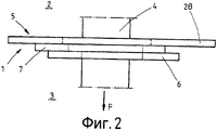
фиг. 2 - соответствующий фиг. 1 вид сверху шлюза;FIG. 2 - corresponding to FIG. 1 top view of the gateway;

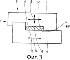
фиг. 3 - первый альтернативный вариант осуществления изобретения из фиг. 1;FIG. 3 is a first alternative embodiment of the invention from FIG. one;

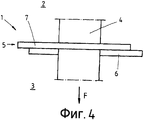
фиг. 4 - соответствующий фиг. 3 вид сверху шлюза;FIG. 4 - corresponding to FIG. 3 top view of the gateway;

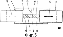
фиг. 5 - второй альтернативный вариант осуществления изобретения из фиг. 1;FIG. 5 is a second alternative embodiment of the invention from FIG. one;

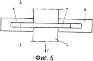
фиг. 6 - соответствующий фиг. 5 вид сверху шлюза;FIG. 6 - corresponding to FIG. 5 top view of the gateway;

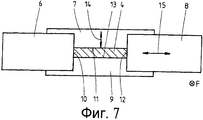
фиг. 7 - третий альтернативный вариант осуществления изобретения из фиг. 1;FIG. 7 is a third alternative embodiment of the invention from FIG. one;

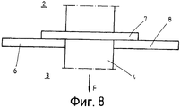
фиг. 8 - соответствующий фиг. 7 вид сверху шлюза;FIG. 8 - corresponding to FIG. 7 top view of the gateway;

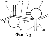
фиг. 9а - шлюз с двумя шлюзовыми ступенями при рассмотрении поперек направления транспортировки полосы;FIG. 9a - a lock with two lock steps when viewed across the direction of transportation of the strip;

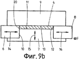
фиг. 9b - соответствующий фиг. 9а вид при рассмотрении в направлении транспортировки полосы;FIG. 9b - corresponding to FIG. 9a is a view when viewed in the direction of transportation of the strip;

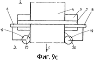
фиг. 9с - соответствующий фиг. 9а вид сверху;FIG. 9c is the corresponding FIG. 9a is a top view;

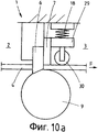
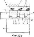
фиг. 10а - альтернативное выполнение шлюза при рассмотрении поперек направления транспортировки полосы;FIG. 10a is an alternative embodiment of the gateway when viewed across the direction of transport of the strip;

фиг. 10b - соответствующий фиг. 10а вид при рассмотрении в направлении транспортировки полосы;FIG. 10b is the corresponding FIG. 10a is a view when viewed in the direction of transportation of the strip;

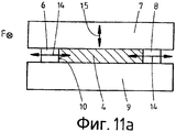
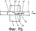
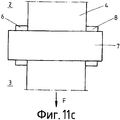
фиг. 11а - альтернативное выполнение шлюза при рассмотрении в направлении транспортировки полосы;FIG. 11a is an alternative embodiment of the gateway when viewed in the direction of transportation of the strip;

фиг. 11b - соответствующий фиг. 11а вид при рассмотрении поперек направления транспортировки полосы;FIG. 11b is the corresponding FIG. 11a is a view when viewed across the direction of transportation of the strip;

фиг. 11с - соответствующий фиг. 11а вид сверху;FIG. 11c is the corresponding FIG. 11 a top view;

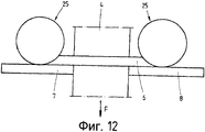
фиг. 12 - шлюз со средством замены для заслонки;FIG. 12 - gateway with replacement means for the shutter;

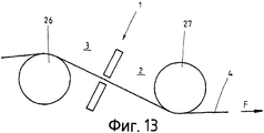
фиг. 13 - шлюз с расположенными перед и за ним роликами для отклонения герметизируемой полосы.FIG. 13 - a lock with rollers located in front of and behind it to deflect the sealing strip.

На фиг. 1 и 2 изображен шлюз 1, который герметизирует первую камеру 2 относительно второй камеры 3. Между обеими камерами 2, 3 имеется разность давлений, для поддержания которой требуется шлюз 1. Шлюз 1 обеспечивает непрерывное прохождение полосы 4, которая движется через него в направлении F транспортировки.In FIG. 1 and 2, a gateway 1 is shown, which seals the first chamber 2 relative to the second chamber 3. There is a pressure difference between the two chambers 2, 3, for which the gateway 1 is required. The gateway 1 provides a continuous passage of the strip 4, which moves through it in the transport direction F .

Для герметизации полосы 4 предусмотрено уплотняющее средство 5. Оно состоит в данном случае из двух заслонок 6, 7, которые выполнены в виде пластин и имеют соответствующее прямоугольное отверстие 16, 17. Размеры отверстий 16, 17 выбраны так, что их ширина и высота больше соответственно максимальной ширины и, соответственно, высоты герметизируемой полосы 4.For sealing the strip 4, sealing means 5 is provided. It consists in this case of two shutters 6, 7, which are made in the form of plates and have a corresponding rectangular hole 16, 17. The dimensions of the holes 16, 17 are selected so that their width and height are larger, respectively maximum width and, accordingly, height of the sealed strip 4.

Заслонка 6 имеет две уплотняющие поверхности 10, 11, а заслонка 7 - две уплотняющие поверхности 12, 13. Как видно на фиг. 2, обе заслонки 6, 7 плотно (герметично) прилегают друг к другу. При этом заслонка 7 прилегает к выполненной в виде пластины перегородке 28 между камерами.The damper 6 has two sealing surfaces 10, 11, and the damper 7 has two sealing surfaces 12, 13. As can be seen in FIG. 2, both shutters 6, 7 fit tightly (hermetically) to each other. In this case, the shutter 7 is adjacent to the plate-shaped partition 28 between the chambers.

На фиг. 1 схематично обозначены исполнительные элементы 14, 15, которые служат для перемещения заслонок 6, 7 в их плоскости пластин. Это происходит до тех пор, пока соответствующие уплотняющие поверхности 10, 11, 12, 13 не будут прилегать к полосе 4, в результате чего она герметизирована тогда между камерами 2, 3.In FIG. 1, the actuators 14, 15 are schematically indicated, which serve to move the shutters 6, 7 in their plane of the plates. This happens until the corresponding sealing surfaces 10, 11, 12, 13 are adjacent to the strip 4, as a result of which it is then sealed between the chambers 2, 3.

Следовательно, герметизация происходит за счет конгруэнтной по форме контактной зоны между заслонками 6, 7 и полосой 4. Для подгонки к актуально герметизируемой полосе 4 заслонки 6, 7 подводятся к полосе 4 согласно ее ширине и толщине. Заслонки 6, 7 могут позиционироваться дополнительными, следующими за контуром полосы направляющими элементами, например направляющими роликами (не показаны). Герметизация заслонок 6, 7 между собой происходит за счет поверхностного контакта или, соответственно, отдельных уплотняющих элементов, в частности уплотняющих поверхностей (не показаны). Герметизация заслонок 6, 7 от перегородки 28 происходит также за счет контактных или уплотняющих элементов (уплотняющих поверхностей).Therefore, sealing occurs due to the shape-congruent contact zone between the shutters 6, 7 and strip 4. For fitting to the actually sealed strip 4, the shutters 6, 7 are fed to the strip 4 according to its width and thickness. The flaps 6, 7 can be positioned with additional guiding elements following the contour of the strip, for example guide rollers (not shown). The sealing of the shutters 6, 7 with each other occurs due to surface contact or, accordingly, individual sealing elements, in particular sealing surfaces (not shown). The sealing of the shutters 6, 7 from the partition 28 also occurs due to contact or sealing elements (sealing surfaces).

Альтернативный фиг. 1 и 2 вариант осуществления изобретения изображен на фиг. 3 и 4. Здесь также предусмотрено две заслонки 6, 7, каждая из которых имеет вырез, который задает две перпендикулярные друг другу уплотняющие поверхности 10, 11 (для заслонки 6) и, соответственно, 12, 13 (для заслонки 7). Аналогично варианту согласно фиг. 1 и 2 также здесь предусмотрено, что обе заслонки 6, 7 передвигаются посредством исполнительных элементов 14, 15 так, что, в целом, образуется проходной канал для прохождения полосы 4, который точно соответствует форме поперечного сечения полосы.An alternative to FIG. 1 and 2, an embodiment of the invention is shown in FIG. 3 and 4. There are also two shutters 6, 7, each of which has a cutout that defines two sealing surfaces perpendicular to each other 10, 11 (for shutter 6) and, accordingly, 12, 13 (for shutter 7). Similarly to the embodiment of FIG. 1 and 2, it is also provided here that both shutters 6, 7 are moved by means of actuators 14, 15 so that, in general, a passage channel is formed for passing the strip 4, which exactly matches the shape of the cross section of the strip.

В другом альтернативном варианте согласно фиг. 5 и 6 предусмотрено четыре заслонки 6, 7, 8, 9, перемещаемые (за исключением неподвижной заслонки 9) посредством исполнительных элементов 14, 15 в положение, в котором их соответствующие уплотняющие поверхности 10, 11, 12, 13 образуют проходной канал для полосы 4, также точно соответствующий форме ее поперечного сечения.In another alternative embodiment of FIG. 5 and 6, four flaps 6, 7, 8, 9 are provided, movable (with the exception of the fixed flap 9) by means of actuators 14, 15 to a position in which their respective sealing surfaces 10, 11, 12, 13 form a passage channel for strip 4 also exactly corresponding to the shape of its cross section.

Как следует из вида сверху на фиг. 6, обе заслонки 6, 8 выполнены в разрезе U-образными; в образовавшийся промежуток между обоими плечами U-образной структуры вставлены заслонки 7 и, соответственно, 9.As follows from the top view of FIG. 6, both shutters 6, 8 are cut in a U-shape; in the resulting gap between both shoulders of the U-shaped structure inserted shutter 7 and, accordingly, 9.

На фиг. 7 и 8 изображено другое альтернативное выполнение уплотняющих средств с четырьмя заслонками 6, 7, 8, 9.In FIG. 7 and 8 show another alternative embodiment of sealing means with four shutters 6, 7, 8, 9.

На фиг. 9а, 9b, 9с в разных видах изображен шлюз 1 с двумя расположенными друг за другом в направлении F транспортировки ступенями. Одна из заслонок, а именно заслонка 9, выполнена здесь в виде ролика. Он взаимодействует с тремя выполненными в виде пластин заслонками 6, 7, 8, чтобы задавать в описанной манере прямоугольный проходной канал для полосы 4.In FIG. 9a, 9b, 9c in different views shows the gateway 1 with two steps arranged one after another in the transport direction F. One of the shutters, namely shutter 9, is made here in the form of a roller. It interacts with three shutters 6, 7, 8 made in the form of plates to define, in the described manner, a rectangular passage channel for strip 4.

На фиг. 9с видно два расположенных по бокам полосы 4 направляющих ролика 19, которые набегают на кромку 20 полосы 4 и тем самым центрируют ее относительно уплотняющего средства. Направляющие ролики 19 расположены неподвижно на заслонках. За счет этого заслонки 6, 7 могут быть выровнены в зависимости от актуального положения кромки полосы.In FIG. 9c, two guide rollers 19 located on the sides of the strip 4 are seen which run onto the edge 20 of the strip 4 and thereby center it relative to the sealing means. The guide rollers 19 are stationary on the shutters. Due to this, the shutters 6, 7 can be aligned depending on the current position of the strip edge.

Направляющие ролики 19 могут быть неподвижно закреплены также на шлюзе или его раме и направлять полосу посередине шлюза.The guide rollers 19 can be fixedly mounted also on the lock or its frame and guide the strip in the middle of the lock.

Оба варианта возможны, однако последний имеет то преимущество, что полоса удерживается посередине (регулирование середины полосы) и заслонка должна отслеживать только небольшие отклонения. При этом возникают меньшие усилия, чем в первом решении.Both options are possible, but the latter has the advantage that the strip is held in the middle (regulation of the middle of the strip) and the damper should track only small deviations. In this case, less effort arises than in the first solution.

Как видно на фиг. 9а, для лучшего направления полосы она в этом случае лишь частично обвивает ролик 9, так что могут быть предотвращены поперечные изгибы или дефекты плоскости.As seen in FIG. 9a, for a better direction of the strip, in this case it only partially wraps around the roller 9, so that lateral bends or plane defects can be prevented.

Заслонки могут позиционироваться также в этом случае дополнительными, следующими за контуром полосы направляющими элементами.The dampers can also be positioned in this case by additional guiding elements following the strip contour.

На фиг. 10а и 10b видно, что заслонки (здесь заслонка 7) могут быть предварительно нагружены пружинами 18 в направлении поверхности полосы, чтобы повысить степень уплотнения. Здесь предусмотрена нагруженная пружинами 18 траверса 29, причем она несет заслонку 7. За счет роликов 30 траверса 29 расположена на определенном расстоянии от поверхности полосы, в результате чего задается также положение заслонки 7. За счет предварительного нагружения пружин 18 траверса 29 подгоняется к актуальному контуру и/или толщине полосы. Заслонка 7 следует за траверсой 29. За счет этого возможны уменьшение износа и, тем самым, повышение стойкости уплотняющей поверхности 11 заслонки 7.In FIG. 10a and 10b, it can be seen that the shutters (here shutter 7) can be preloaded by springs 18 in the direction of the strip surface in order to increase the degree of compaction. A traverse 29, loaded with springs 18, is provided here, and it carries a shutter 7. Due to the rollers 30, the traverse 29 is located at a certain distance from the strip surface, as a result of which the position of the shutter 7 is also set. / or strip thickness. The shutter 7 follows the traverse 29. Due to this, it is possible to reduce wear and, thereby, increase the resistance of the sealing surface 11 of the shutter 7.

Герметизация по ширине полосы происходит посредством перемещаемых вбок заслонок.Sealing across the width of the strip occurs by means of side-mounted dampers.

На фиг. 11а, 11b, 11с изображен вариант осуществления изобретения, в котором предусмотрены средства 21 для подгонки рабочей высоты или ширины заслонки. Здесь заслонка 6 выполнена составной, т.е. она имеет первую 6' и вторую 6'' части. Как следует из фиг. 11b, обе части 6', 6'' срезаны под плоским углом к направлению F транспортировки, т.е. имеются контактные поверхности 22, 23, которыми части 6', 6'' прилегают друг к другу. Далее схематично обозначен элемент 24 перемещения, с помощью которого часть 6'' может перемещаться относительно части 6' в направлении F транспортировки. За счет скошенного хода контактных поверхностей 22, 23 изменяется эффективная рабочая высота заслонки 6, так что она может быть установлена на нужную высоту. Возможна подгонка заслонки 6 к толщине полосы 4.In FIG. 11a, 11b, 11c shows an embodiment of the invention in which means 21 are provided for adjusting the working height or width of the shutter. Here, the shutter 6 is made integral, i.e. it has a first 6 'and a second 6' 'part. As follows from FIG. 11b, both parts 6 ′, 6 ″ are cut at a flat angle to the transport direction F, i.e. there are contact surfaces 22, 23 with which the parts 6 ', 6' 'abut against each other. Next, a movement member 24 is schematically indicated by which the part 6 ″ can be moved relative to the part 6 ′ in the transport direction F. Due to the beveled stroke of the contact surfaces 22, 23, the effective working height of the shutter 6 is changed so that it can be set to the desired height. It is possible to adjust the shutter 6 to the thickness of the strip 4.

На фиг. 12 схематично изображено средство 25 замены, с помощью которого можно при текущей эксплуатации заменить заслонку 6. Целью этого варианта изобретения является, следовательно, замена уплотнения во время текущего процесса или минимизация времени простоев, когда заслонку приходится заменить вследствие износа. Заслонка с изношенной уплотняющей поверхностью может быть извлечена вбок из рабочей зоны шлюза. На другой стороне может быть подведена новая заслонка. Замена может осуществляться, в частности, даже при существующей разности давлений между камерами 2, 3. При этом возможна как непрерывная замена заслонки, так и, при необходимости, периодическая замена. Описанное средство замены применимо, в принципе, для всех заслонок.In FIG. 12 schematically depicts replacement means 25 with which it is possible to replace the shutter 6 during current operation. The aim of this embodiment of the invention is therefore to replace the seal during the current process or to minimize downtime when the shutter has to be replaced due to wear. A damper with a worn sealing surface can be removed sideways from the working area of the airlock. On the other side, a new shutter can be brought up. Replacement can be carried out, in particular, even with the existing pressure difference between the chambers 2, 3. In this case, both a continuous replacement of the shutter and, if necessary, periodic replacement are possible. The described replacement means is applicable, in principle, to all dampers.

На фиг. 13 видно, как стабилизация полосы в зоне шлюза 1 может происходить за счет отклонения полосы. Посредством двух роликов 26, 27 происходит двойное отклонение полосы 4. В результате полоса тянется в одной плоскости и дополнительно стабилизируется между роликами за счет изгиба. Видимое образование дефектов плоскостности и поперечных изгибов уменьшается. Из этого следуют уменьшение износа уплотняющих элементов и уменьшение утечек.In FIG. 13 shows how stabilization of the strip in the area of the gateway 1 can occur due to deviation of the strip. By means of two rollers 26, 27 there is a double deflection of strip 4. As a result, the strip stretches in the same plane and further stabilizes between the rollers due to bending. The visible formation of flatness defects and transverse bends is reduced. This results in reduced wear on the sealing elements and less leakage.

Отклоняющие ролики 26, 27 могут дополнительно использоваться для регулирования положения полосы. С этим регулированием полоса 4 может также целенаправленно перемещаться. Этим можно сделать равномерным или минимизировать износ уплотняющих поверхностей заслонок по ширине полосы. При этом уплотняющие поверхности у кромки полосы подводятся (осуществляют слежение) синхронно.Deflecting rollers 26, 27 can be additionally used to adjust the position of the strip. With this adjustment, lane 4 can also be purposefully moved. This can be done uniformly or to minimize wear on the sealing surfaces of the shutters along the width of the strip. In this case, the sealing surfaces at the edge of the strip are brought (tracking) synchronously.

Таким образом, возникает шлюз простой и недорогой конструкции, который обладает хорошей уплотняющей характеристикой за счет геометрического замыкания. Предложенные в изобретении заслонки располагаются вплотную друг к другу и смещаются так, что образуется проходной канал, соответствующий форме поперечного сечения полосы.Thus, a gateway of a simple and inexpensive design arises, which has a good sealing characteristic due to a geometric circuit. The dampers proposed in the invention are located close to each other and are displaced so that a passage channel is formed corresponding to the shape of the cross section of the strip.

Подгонка к новым размерам полосы может осуществляться двух типов: активная подгонка преследует своей целью управляемое изменение установки заслонок, а при пассивной подгонке полоса вдавливается в нужное положение уплотняющими поверхностями заслонок.The adjustment to the new dimensions of the strip can be carried out in two types: the active adjustment aims at a controlled change in the installation of the dampers, and with passive fitting, the strip is pressed into position by the sealing surfaces of the dampers.

Благодаря предложенному решению могут герметизироваться друг относительно друга камеры с разными давлениями, а также камеры с одинаковыми давлениями, в которых находятся различные технологические среды, в частности технологические газы, а также жидкости. Если предусмотрены боковые ролики, набегающие на кромку полосы, то ими может достигаться хорошее боковое направление полосы. Движущиеся по поверхности полосы ролики могут использоваться для направления заслонок.Thanks to the proposed solution, chambers with different pressures, as well as chambers with the same pressures, in which various process fluids, in particular process gases, and liquids, can be sealed relative to each other. If side rollers are provided running on the edge of the strip, they can achieve good lateral direction of the strip. Rollers moving along the surface of the strip can be used to guide the dampers.

Перечень ссылочных позицийList of Reference Items

1 - шлюз для полосы1 - gateway for the strip

2 - первая камера2 - first camera

3 - вторая камера3 - second camera

4 - полоса4 - strip

5 - уплотняющее средство5 - sealing means

6 - заслонка6 - shutter

6' - часть заслонки6 '- part of the shutter

6'' - часть заслонки6 '' - part of the shutter

7 - заслонка7 - shutter

8 - заслонка8 - shutter

9 - заслонка9 - shutter

10 - уплотняющая поверхность10 - sealing surface

11 - уплотняющая поверхность11 - sealing surface

12 - уплотняющая поверхность12 - sealing surface

13 - уплотняющая поверхность13 - sealing surface

14 - исполнительный элемент14 - actuator

15 - исполнительный элемент15 - actuator

16 - прямоугольное отверстие16 - rectangular hole

17 - прямоугольное отверстие17 - rectangular hole

18 - пружина18 - spring

19 - направляющий ролик19 - a directing roller

20 - кромка полосы20 - strip edge

21 - средство для подгонки рабочей высоты или рабочей ширины21 - means for adjusting the working height or working width

22 - контактная поверхность22 - contact surface

23 - контактная поверхность23 - contact surface

24 - элемент перемещения24 - displacement element

25 - средство для замены25 - replacement tool

26 - ролик26 - movie

27 - ролик27 - movie

28 - перегородка между камерами28 - the partition between the cameras

29 - траверса29 - traverse

30 - ролик30 - roller

F - направление транспортировкиF - direction of transportation

Claims (93)

1. Шлюз (1) для полосы для герметизации первой камеры (2) относительно второй камеры (3), причем полоса (4), в частности металлическая полоса, проходит через обе камеры (2, 3), при этом для герметизации камер (2, 3) предусмотрено, по меньшей мере, одно уплотняющее средство (5), отличающийся тем, что уплотняющее средство (5) содержит, по меньшей мере, две подвижные по отношению друг к другу заслонки (6, 7, 8, 9), имеющие, по меньшей мере, одну уплотняющую поверхность (10, 11, 12, 13), подогнанную к краевому контуру герметизируемой полосы (4).1. The gateway (1) for the strip for sealing the first chamber (2) relative to the second chamber (3), and the strip (4), in particular a metal strip, passes through both chambers (2, 3), while for sealing the chambers (2 , 3) at least one sealing means (5) is provided, characterized in that the sealing means (5) comprises at least two shutters (6, 7, 8, 9) movable with respect to each other, having at least one sealing surface (10, 11, 12, 13) fitted to the edge contour of the sealing strip (4). 2. Шлюз по п.1, отличающийся тем, что, по меньшей мере, две заслонки (6, 7, 8, 9) выполнены в виде пластин и расположены параллельно друг другу и прилегая друг к другу.2. The gateway according to claim 1, characterized in that at least two shutters (6, 7, 8, 9) are made in the form of plates and are parallel to each other and adjacent to each other. 3. Шлюз по п.1 или 2, отличающийся тем, что, по меньшей мере, одна часть заслонок (6, 7, 8, 9) связана с исполнительными элементами (14, 15) для перемещения заслонки (6, 7, 8, 9) перпендикулярно направлению (F) транспортировки полосы (4).3. The gateway according to claim 1 or 2, characterized in that at least one part of the shutters (6, 7, 8, 9) is connected with actuators (14, 15) for moving the shutter (6, 7, 8, 9) perpendicular to the direction (F) of transportation of the strip (4). 4. Шлюз по п.1 или 2, отличающийся тем, что предусмотрены две подвижные по отношению друг к другу заслонки (6, 7), каждая из которых имеет прямоугольное отверстие (16, 17) для прохождения полосы (4).4. The gateway according to claim 1 or 2, characterized in that two flaps (6, 7) are movable with respect to each other, each of which has a rectangular hole (16, 17) for passing the strip (4). 5. Шлюз по п.3, отличающийся тем, что предусмотрены две подвижные по отношению друг к другу заслонки (6, 7), каждая из которых имеет прямоугольное отверстие (16, 17) для прохождения полосы (4).5. The gateway according to claim 3, characterized in that two flaps (6, 7) are movable with respect to each other, each of which has a rectangular hole (16, 17) for passing the strip (4). 6. Шлюз по п.1 или 2, отличающийся тем, что предусмотрены две подвижные по отношению друг к другу заслонки (6, 7), каждая из которых имеет расположенные перпендикулярно друг другу уплотняющие поверхности (10, 11, 12, 13).6. The gateway according to claim 1 or 2, characterized in that two flaps (6, 7) are movable with respect to each other, each of which has sealing surfaces perpendicular to each other (10, 11, 12, 13). 7. Шлюз по п.3, отличающийся тем, что предусмотрены две подвижные по отношению друг к другу заслонки (6, 7), каждая из которых имеет расположенные перпендикулярно друг другу уплотняющие поверхности (10, 11, 12, 13).7. A gateway according to claim 3, characterized in that two flaps (6, 7) are movable with respect to each other, each of which has sealing surfaces perpendicular to each other (10, 11, 12, 13). 8. Шлюз по п.1 или 2, отличающийся тем, что предусмотрены четыре подвижные по отношению друг к другу заслонки (6, 7, 8, 9), каждая из которых имеет проходящую прямо уплотняющую поверхность (10, 11, 12, 13).8. The gateway according to claim 1 or 2, characterized in that four flaps (6, 7, 8, 9) are movable with respect to each other, each of which has a straight sealing surface passing directly (10, 11, 12, 13) . 9. Шлюз по п.3, отличающийся тем, что предусмотрены четыре подвижные по отношению друг к другу заслонки (6, 7, 8, 9), каждая из которых имеет проходящую прямо уплотняющую поверхность (10, 11, 12, 13).9. The gateway according to claim 3, characterized in that four flaps (6, 7, 8, 9) are movable with respect to each other, each of which has a straight sealing surface passing directly (10, 11, 12, 13). 10. Шлюз по п.1 или 2, отличающийся тем, что заслонка (9) выполнена в виде ролика.10. The gateway according to claim 1 or 2, characterized in that the shutter (9) is made in the form of a roller. 11. Шлюз по п.3, отличающийся тем, что заслонка (9) выполнена в виде ролика.11. The gateway according to claim 3, characterized in that the shutter (9) is made in the form of a roller. 12. Шлюз по одному из пп.1, 2, 5, 7, 9 или 11, отличающийся тем, что, по меньшей мере, одна из заслонок (6, 7, 8, 9) выполнена с возможностью прижатия к поверхности полосы своей уплотняющей поверхностью (10, 11, 12, 13) посредством пружины (18).12. The gateway according to one of claims 1, 2, 5, 7, 9 or 11, characterized in that at least one of the shutters (6, 7, 8, 9) is made with the possibility of pressing its sealing strip to the surface surface (10, 11, 12, 13) by means of a spring (18). 13. Шлюз по п.3, отличающийся тем, что, по меньшей мере, одна из заслонок (6, 7, 8, 9) выполнена с возможностью прижатия к поверхности полосы своей уплотняющей поверхностью (10, 11, 12, 13) посредством пружины (18).13. The gateway according to claim 3, characterized in that at least one of the shutters (6, 7, 8, 9) is made with the possibility of pressing against the strip surface with its sealing surface (10, 11, 12, 13) by means of a spring (eighteen). 14. Шлюз по п.4, отличающийся тем, что, по меньшей мере, одна из заслонок (6, 7, 8, 9) выполнена с возможностью прижатия к поверхности полосы своей уплотняющей поверхностью (10, 11, 12, 13) посредством пружины (18).14. The gateway according to claim 4, characterized in that at least one of the shutters (6, 7, 8, 9) is made with the possibility of pressing against the strip surface with its sealing surface (10, 11, 12, 13) by means of a spring (eighteen). 15. Шлюз по п.6, отличающийся тем, что, по меньшей мере, одна из заслонок (6, 7, 8, 9) выполнена с возможностью прижатия к поверхности полосы своей уплотняющей поверхностью (10, 11, 12, 13) посредством пружины (18).15. The gateway according to claim 6, characterized in that at least one of the shutters (6, 7, 8, 9) is configured to press against the strip surface with its sealing surface (10, 11, 12, 13) by means of a spring (eighteen). 16. Шлюз по п.8, отличающийся тем, что, по меньшей мере, одна из заслонок (6, 7, 8, 9) выполнена с возможностью прижатия к поверхности полосы своей уплотняющей поверхностью (10, 11, 12, 13) посредством пружины (18).16. The gateway according to claim 8, characterized in that at least one of the shutters (6, 7, 8, 9) is made with the possibility of pressing against the strip surface with its sealing surface (10, 11, 12, 13) by means of a spring (eighteen). 17. Шлюз по п.10, отличающийся тем, что, по меньшей мере, одна из заслонок (6, 7, 8, 9) выполнена с возможностью прижатия к поверхности полосы своей уплотняющей поверхностью (10, 11, 12, 13) посредством пружины (18).17. The gateway according to claim 10, characterized in that at least one of the shutters (6, 7, 8, 9) is made with the possibility of pressing against the strip surface with its sealing surface (10, 11, 12, 13) by means of a spring (eighteen). 18. Шлюз по одному из пп.1, 2, 5, 7, 9, 11, 13-17, отличающийся тем, что предусмотрен, по меньшей мере, один направляющий ролик (19), выполненный с возможностью набегания на кромку (20) полосы и направления полосы (4) относительно шлюза (1).18. The gateway according to one of claims 1, 2, 5, 7, 9, 11, 13-17, characterized in that at least one guide roller (19) is provided, which is configured to run on the edge (20) lanes and lane directions (4) relative to the gateway (1). 19. Шлюз по п.3, отличающийся тем, что предусмотрен, по меньшей мере, один направляющий ролик (19), выполненный с возможностью набегания на кромку (20) полосы и направления полосы (4) относительно шлюза (1).19. The gateway according to claim 3, characterized in that at least one guide roller (19) is provided, configured to run onto the edge (20) of the strip and the direction of the strip (4) relative to the gateway (1). 20. Шлюз по п.4, отличающийся тем, что предусмотрен, по меньшей мере, один направляющий ролик (19), выполненный с возможностью набегания на кромку (20) полосы и направления полосы (4) относительно шлюза (1).20. The gateway according to claim 4, characterized in that at least one guide roller (19) is provided, configured to run onto the edge (20) of the strip and the direction of the strip (4) relative to the gateway (1). 21. Шлюз по п.6, отличающийся тем, что предусмотрен, по меньшей мере, один направляющий ролик (19), выполненный с возможностью набегания на кромку (20) полосы и направления полосы (4) относительно шлюза (1).21. The gateway according to claim 6, characterized in that at least one guide roller (19) is provided, configured to run onto the edge (20) of the strip and the direction of the strip (4) relative to the gateway (1). 22. Шлюз по п.8, отличающийся тем, что предусмотрен, по меньшей мере, один направляющий ролик (19), выполненный с возможностью набегания на кромку (20) полосы и направления полосы (4) относительно шлюза (1).22. The gateway according to claim 8, characterized in that at least one guide roller (19) is provided, configured to run onto the edge (20) of the strip and the direction of the strip (4) relative to the gateway (1). 23. Шлюз по п.10, отличающийся тем, что предусмотрен, по меньшей мере, один направляющий ролик (19), выполненный с возможностью набегания на кромку (20) полосы и направления полосы (4) относительно шлюза (1).23. The gateway according to claim 10, characterized in that at least one guide roller (19) is provided, configured to run onto the edge (20) of the strip and the direction of the strip (4) relative to the gateway (1). 24. Шлюз по п.12, отличающийся тем, что предусмотрен, по меньшей мере, один направляющий ролик (19), выполненный с возможностью набегания на кромку (20) полосы и направления полосы (4) относительно шлюза (1).24. The gateway according to claim 12, characterized in that at least one guide roller (19) is provided, configured to run onto the edge (20) of the strip and the direction of the strip (4) relative to the gateway (1). 25. Шлюз по одному из пп.1, 2, 5, 7, 9, 11, 13-17, 19-24, отличающийся тем, что, по меньшей мере, одна заслонка (6, 7, 8, 9) оснащена средствами (21) для подгонки рабочей высоты или рабочей ширины.25. The gateway according to one of claims 1, 2, 5, 7, 9, 11, 13-17, 19-24, characterized in that at least one shutter (6, 7, 8, 9) is equipped with means (21) to adjust the working height or working width. 26. Шлюз по п.3, отличающийся тем, что, по меньшей мере, одна заслонка (6, 7, 8, 9) оснащена средствами (21) для подгонки рабочей высоты или рабочей ширины.26. The gateway according to claim 3, characterized in that at least one shutter (6, 7, 8, 9) is equipped with means (21) for adjusting the working height or working width. 27. Шлюз по п.4, отличающийся тем, что, по меньшей мере, одна заслонка (6, 7, 8, 9) оснащена средствами (21) для подгонки рабочей высоты или рабочей ширины.27. The gateway according to claim 4, characterized in that at least one shutter (6, 7, 8, 9) is equipped with means (21) for adjusting the working height or working width. 28. Шлюз по п.6, отличающийся тем, что, по меньшей мере, одна заслонка (6, 7, 8, 9) оснащена средствами (21) для подгонки рабочей высоты или рабочей ширины.28. The gateway according to claim 6, characterized in that at least one shutter (6, 7, 8, 9) is equipped with means (21) for adjusting the working height or working width. 29. Шлюз по п.8, отличающийся тем, что, по меньшей мере, одна заслонка (6, 7, 8, 9) оснащена средствами (21) для подгонки рабочей высоты или рабочей ширины.29. The gateway according to claim 8, characterized in that at least one shutter (6, 7, 8, 9) is equipped with means (21) for adjusting the working height or working width. 30. Шлюз по п.10, отличающийся тем, что, по меньшей мере, одна заслонка (6, 7, 8, 9) оснащена средствами (21) для подгонки рабочей высоты или рабочей ширины.30. The gateway according to claim 10, characterized in that at least one shutter (6, 7, 8, 9) is equipped with means (21) for adjusting the working height or working width. 31. Шлюз по п.12, отличающийся тем, что, по меньшей мере, одна заслонка (6, 7, 8, 9) оснащена средствами (21).для подгонки рабочей высоты или рабочей ширины.31. The gateway according to claim 12, characterized in that at least one shutter (6, 7, 8, 9) is equipped with means (21) for adjusting the working height or working width. 32. Шлюз по п.18, отличающийся тем, что, по меньшей мере, одна заслонка (6, 7, 8, 9) оснащена средствами (21) для подгонки рабочей высоты или рабочей ширины.32. The gateway according to claim 18, characterized in that at least one shutter (6, 7, 8, 9) is equipped with means (21) for adjusting the working height or working width. 33. Шлюз по п.25, отличающийся тем, что средства (21) для подгонки рабочей высоты или ширины реализованы двумя частями (6', 6") заслонки, которые прилегают друг к другу срезанными под углом к направлению (F) транспортировки полосы (4) контактными поверхностями (22, 23), причем, по меньшей мере, одна из частей (6', 6") выполнена с возможностью позиционирования в направлении (F) транспортировки полосы посредством элемента (24) перемещения.33. The gateway according to claim 25, characterized in that the means (21) for adjusting the working height or width are realized by two parts (6 ', 6 ") of the shutter, which are adjacent to each other cut off at an angle to the direction (F) of transporting the strip ( 4) contact surfaces (22, 23), wherein at least one of the parts (6 ', 6 ") is arranged to be positioned in the direction (F) of transporting the strip by means of the movement member (24). 34. Шлюз по одному из пп.26-32, отличающийся тем, что средства (21) для подгонки рабочей высоты или ширины реализованы двумя частями (6', 6") заслонки, которые прилегают друг к другу срезанными под углом к направлению (F) транспортировки полосы (4) контактными поверхностями (22, 23), причем, по меньшей мере, одна из частей (6', 6") выполнена с возможностью позиционирования в направлении (F) транспортировки полосы посредством элемента (24) перемещения.34. Gateway according to one of paragraphs.26-32, characterized in that the means (21) for adjusting the working height or width are realized by two parts (6 ', 6 ") of the shutter, which are adjacent to each other cut off at an angle to the direction (F ) transporting the strip (4) by the contact surfaces (22, 23), wherein at least one of the parts (6 ', 6 ") is configured to be positioned in the direction (F) of transporting the strip by the movement member (24). 35. Шлюз по одному из пп.1, 2, 5, 7, 9, 11, 13-17, 19-24, 26-33, отличающийся тем, что предусмотрено средство (25) замены, выполненное с возможностью вдвигания заслонки (6, 7, 8, 9) в уплотняемую зону или выдвигания из нее поперек направления (F) транспортировки полосы (4).35. The gateway according to one of claims 1, 2, 5, 7, 9, 11, 13-17, 19-24, 26-33, characterized in that there is provided a replacement tool (25) made with the possibility of sliding the shutter (6 , 7, 8, 9) into the sealing zone or advancing out of it across the direction (F) of transporting the strip (4). 36. Шлюз по п.3, отличающийся тем, что предусмотрено средство (25) замены, выполненное с возможностью вдвигания заслонки (6, 7, 8, 9) в уплотняемую зону или выдвигания из нее поперек направления (F) транспортировки полосы (4).36. The gateway according to claim 3, characterized in that there is provided a means (25) of replacement made with the possibility of pushing the shutter (6, 7, 8, 9) into the sealing area or sliding out of it across the direction (F) of transporting the strip (4) . 37. Шлюз по п.4, отличающийся тем, что предусмотрено средство (25) замены, выполненное с возможностью вдвигания заслонки (6, 7, 8, 9) в уплотняемую зону или выдвигания из нее поперек направления (F) транспортировки полосы (4).37. The gateway according to claim 4, characterized in that there is provided a means (25) of replacement made with the possibility of sliding the shutter (6, 7, 8, 9) into the sealing area or sliding out from it across the direction (F) of transporting the strip (4) . 38. Шлюз по п.6, отличающийся тем, что предусмотрено средство (25) замены, выполненное с возможностью вдвигания заслонки (6, 7, 8, 9) в уплотняемую зону или выдвигания из нее поперек направления (F) транспортировки полосы (4).38. The gateway according to claim 6, characterized in that there is provided a means (25) of replacement made with the possibility of sliding the shutter (6, 7, 8, 9) into the sealing area or sliding out from it across the direction (F) of transporting the strip (4) . 39. Шлюз по п.8, отличающийся тем, что предусмотрено средство (25) замены, выполненное с возможностью вдвигания заслонки (6, 7, 8, 9) в уплотняемую зону или выдвигания из нее поперек направления (F) транспортировки полосы (4).39. The gateway according to claim 8, characterized in that a replacement means (25) is provided, made with the possibility of pushing the shutter (6, 7, 8, 9) into the sealing area or extending from it across the direction (F) of transporting the strip (4) . 40. Шлюз по п.10, отличающийся тем, что предусмотрено средство (25) замены, выполненное с возможностью вдвигания заслонки (6, 7, 8, 9) в уплотняемую зону или выдвигания из нее поперек направления (F) транспортировки полосы (4).40. The gateway according to claim 10, characterized in that a replacement means (25) is provided, made with the possibility of pushing the shutter (6, 7, 8, 9) into the sealing area or extending from it across the direction (F) of the strip transport (4) . 41. Шлюз по п.12, отличающийся тем, что предусмотрено средство (25) замены, выполненное с возможностью вдвигания заслонки (6, 7, 8, 9) в уплотняемую зону или выдвигания из нее поперек направления (F) транспортировки полосы (4).41. The gateway according to claim 12, characterized in that a replacement means (25) is provided, which is configured to slide the shutter (6, 7, 8, 9) into the sealing area or to extend from it across the direction (F) of transporting the strip (4) . 42. Шлюз по п.18, отличающийся тем, что предусмотрено средство (25) замены, выполненное с возможностью вдвигания заслонки (6, 7, 8, 9) в уплотняемую зону или выдвигания из нее поперек направления (F) транспортировки полосы (4).42. The gateway according to claim 18, characterized in that there is provided a replacement means (25) configured to slide the shutter (6, 7, 8, 9) into the sealing area or to extend from it across the direction (F) of transporting the strip (4) . 43. Шлюз по п.25, отличающийся тем, что предусмотрено средство (25) замены, выполненное с возможностью вдвигания заслонки (6, 7, 8, 9) в уплотняемую зону или выдвигания из нее поперек направления (F) транспортировки полосы (4).43. The gateway according to claim 25, characterized in that there is provided a means (25) of replacement made with the possibility of sliding the shutter (6, 7, 8, 9) into the sealing area or extending from it across the direction (F) of transporting the strip (4) . 44. Шлюз по п.34, отличающийся тем, что предусмотрено средство (25) замены, выполненное с возможностью вдвигания заслонки (6, 7, 8, 9) в уплотняемую зону или выдвигания из нее поперек направления (F) транспортировки полосы (4).44. The gateway according to claim 34, characterized in that a replacement means (25) is provided, which is capable of sliding the shutter (6, 7, 8, 9) into the sealing area or extending from it across the direction (F) of transporting the strip (4) . 45. Шлюз по одному из пп.1, 2, 5, 7, 9, 11, 13-17, 19-24, 26-33, 36-44, отличающийся тем, что полоса направляется в направлении (F) транспортировки двумя роликами (26, 27) с возможностью ее двойного отклонения до и после заслонок (6, 7, 8, 9).45. The gateway according to one of claims 1, 2, 5, 7, 9, 11, 13-17, 19-24, 26-33, 36-44, characterized in that the strip is guided in the direction (F) of transportation by two rollers (26, 27) with the possibility of its double deflection before and after the shutters (6, 7, 8, 9). 46. Шлюз по п.3, отличающийся тем, что полоса направляется в направлении (F) транспортировки двумя роликами (26, 27) с возможностью ее двойного отклонения до и после заслонок (6, 7, 8, 9).46. The gateway according to claim 3, characterized in that the strip is guided in the direction (F) of transportation by two rollers (26, 27) with the possibility of its double deflection before and after the shutters (6, 7, 8, 9). 47. Шлюз по п.4, отличающийся тем, что полоса направляется в направлении (F) транспортировки двумя роликами (26, 27) с возможностью ее двойного отклонения до и после заслонок (6, 7, 8, 9).47. The gateway according to claim 4, characterized in that the strip is guided in the direction (F) of transportation by two rollers (26, 27) with the possibility of its double deflection before and after the shutters (6, 7, 8, 9). 48. Шлюз по п.6, отличающийся тем, что полоса направляется в направлении (F) транспортировки двумя роликами (26, 27) с возможностью ее двойного отклонения до и после заслонок (6, 7, 8, 9).48. The gateway according to claim 6, characterized in that the strip is guided in the direction (F) of transportation by two rollers (26, 27) with the possibility of its double deflection before and after the shutters (6, 7, 8, 9). 49. Шлюз по п.8, отличающийся тем, что полоса направляется в направлении (F) транспортировки двумя роликами (26, 27) с возможностью ее двойного отклонения до и после заслонок (6, 7, 8, 9).49. The gateway according to claim 8, characterized in that the strip is guided in the direction (F) of transportation by two rollers (26, 27) with the possibility of its double deflection before and after the shutters (6, 7, 8, 9). 50. Шлюз по п.10, отличающийся тем, что полоса направляется в направлении (F) транспортировки двумя роликами (26, 27) с возможностью ее двойного отклонения до и после заслонок (6, 7, 8, 9).50. The gateway according to claim 10, characterized in that the strip is guided in the direction (F) of transportation by two rollers (26, 27) with the possibility of its double deflection before and after the shutters (6, 7, 8, 9). 51. Шлюз по п.12, отличающийся тем, что полоса направляется в направлении (F) транспортировки двумя роликами (26, 27) с возможностью ее двойного отклонения до и после заслонок (6, 7, 8, 9).51. The gateway according to claim 12, characterized in that the strip is guided in the direction (F) of transportation by two rollers (26, 27) with the possibility of its double deflection before and after the shutters (6, 7, 8, 9). 52. Шлюз по п.18, отличающийся тем, что полоса направляется в направлении (F) транспортировки двумя роликами (26, 27) с возможностью ее двойного отклонения до и после заслонок (6, 7, 8, 9).52. The gateway according to claim 18, characterized in that the strip is guided in the direction (F) of transportation by two rollers (26, 27) with the possibility of its double deflection before and after the shutters (6, 7, 8, 9). 53. Шлюз по п.25, отличающийся тем, что полоса направляется в направлении (F) транспортировки двумя роликами (26, 27) с возможностью ее двойного отклонения до и после заслонок (6, 7, 8, 9).53. The gateway according to claim 25, wherein the strip is guided in the direction (F) of transportation by two rollers (26, 27) with the possibility of its double deflection before and after the shutters (6, 7, 8, 9). 54. Шлюз по п.34, отличающийся тем, что полоса направляется в направлении (F) транспортировки двумя роликами (26, 27) с возможностью ее двойного отклонения до и после заслонок (6, 7, 8, 9).54. The gateway according to claim 34, wherein the strip is guided in the direction (F) of transportation by two rollers (26, 27) with the possibility of its double deflection before and after the shutters (6, 7, 8, 9). 55. Шлюз по п.35, отличающийся тем, что полоса направляется в направлении (F) транспортировки двумя роликами (26, 27) с возможностью ее двойного отклонения до и после заслонок (6, 7, 8, 9).55. The gateway according to claim 35, wherein the strip is guided in the direction (F) of transportation by two rollers (26, 27) with the possibility of its double deflection before and after the shutters (6, 7, 8, 9). 56. Шлюз по одному из пп.1, 2, 5, 7, 9, 11, 13-17, 19-24, 26-33, 36-44, 46-55, отличающийся тем, что друг за другом в направлении движения полосы расположено нескольких шлюзовых ступеней.56. The gateway according to one of claims 1, 2, 5, 7, 9, 11, 13-17, 19-24, 26-33, 36-44, 46-55, characterized in that one after the other in the direction of movement strip located several lock steps. 57. Шлюз по п.3, отличающийся тем, что друг за другом в направлении движения полосы расположено несколько шлюзовых ступеней.57. The gateway according to claim 3, characterized in that several lock steps are arranged one after the other in the direction of the strip. 58. Шлюз по п.4, отличающийся тем, что друг за другом в направлении движения полосы расположено несколько шлюзовых ступеней.58. The gateway according to claim 4, characterized in that several gateway steps are located one after the other in the direction of movement of the strip. 59. Шлюз по п.6, отличающийся тем, что друг за другом в направлении движения полосы расположено несколько шлюзовых ступеней.59. The gateway according to claim 6, characterized in that several gateway steps are located one after the other in the direction of movement of the strip. 60. Шлюз по п.8, отличающийся тем, что друг за другом в направлении движения полосы расположено несколько шлюзовых ступеней.60. The gateway according to claim 8, characterized in that several gateway steps are located one after the other in the direction of movement of the strip. 61. Шлюз по п.10, отличающийся тем, что друг за другом в направлении движения полосы расположено несколько шлюзовых ступеней.61. The gateway of claim 10, characterized in that several gateway steps are located one after the other in the direction of movement of the strip. 62. Шлюз по п.12, отличающийся тем, что друг за другом в направлении движения полосы расположено несколько шлюзовых ступеней.62. The gateway according to claim 12, characterized in that several gateway steps are located one after the other in the direction of movement of the strip. 63. Шлюз по п.18, отличающийся тем, что друг за другом в направлении движения полосы расположено несколько шлюзовых ступеней.63. The gateway according to claim 18, characterized in that several lock steps are arranged one after the other in the direction of movement of the strip. 64. Шлюз по п.25, отличающийся тем, что друг за другом в направлении движения полосы расположено несколько шлюзовых ступеней.64. The gateway according to claim 25, characterized in that several gateway steps are located one after the other in the direction of the strip movement. 65. Шлюз по п.34, отличающийся тем, что друг за другом в направлении движения полосы расположено несколько шлюзовых ступеней.65. The gateway according to claim 34, characterized in that several gateway steps are located one after the other in the direction of movement of the strip. 66. Шлюз по п.35, отличающийся тем, что друг за другом в направлении движения полосы расположено несколько шлюзовых ступеней.66. The gateway according to claim 35, characterized in that several gateway steps are located one after the other in the direction of the strip movement. 67. Шлюз по п.45, отличающийся тем, что друг за другом в направлении движения полосы расположено несколько шлюзовых ступеней.67. The gateway according to claim 45, characterized in that several gateway steps are located one after the other in the direction of the strip. 68. Шлюз по одному из пп.1, 2, 5, 7, 9, 11, 13-17, 19-24, 26-33, 36-44, 46-55, 57-67, отличающийся тем, что его используют для герметизации первой камеры (2) с первым уровнем давления относительно второй камеры (3) со вторым уровнем давления, отличающимся от первого уровня давления.68. The gateway according to one of claims 1, 2, 5, 7, 9, 11, 13-17, 19-24, 26-33, 36-44, 46-55, 57-67, characterized in that it is used for sealing the first chamber (2) with a first pressure level relative to the second chamber (3) with a second pressure level different from the first pressure level. 69. Шлюз по п.3, отличающийся тем, что его используют для герметизации первой камеры (2) с первым уровнем давления относительно второй камеры (3) со вторым уровнем давления, отличающимся от первого уровня давления.69. The gateway according to claim 3, characterized in that it is used to seal the first chamber (2) with a first pressure level relative to the second chamber (3) with a second pressure level different from the first pressure level. 70. Шлюз по п.4, отличающийся тем, что его используют для герметизации первой камеры (2) с первым уровнем давления относительно второй камеры (3) со вторым уровнем давления, отличающимся от первого уровня давления.70. The gateway according to claim 4, characterized in that it is used to seal the first chamber (2) with a first pressure level relative to the second chamber (3) with a second pressure level different from the first pressure level. 71. Шлюз по п.6, отличающийся тем, что его используют для герметизации первой камеры (2) с первым уровнем давления относительно второй камеры (3) со вторым уровнем давления, отличающимся от первого уровня давления.71. The gateway according to claim 6, characterized in that it is used to seal the first chamber (2) with a first pressure level relative to the second chamber (3) with a second pressure level different from the first pressure level. 72. Шлюз по п.8, отличающийся тем, что его используют для герметизации первой камеры (2) с первым уровнем давления относительно второй камеры (3) со вторым уровнем давления, отличающимся от первого уровня давления.72. The gateway according to claim 8, characterized in that it is used to seal the first chamber (2) with a first pressure level relative to the second chamber (3) with a second pressure level different from the first pressure level. 73. Шлюз по п.10, отличающийся тем, что его используют для герметизации первой камеры (2) с первым уровнем давления относительно второй камеры (3) со вторым уровнем давления, отличающимся от первого уровня давления.73. The gateway of claim 10, characterized in that it is used to seal the first chamber (2) with a first pressure level relative to the second chamber (3) with a second pressure level different from the first pressure level. 74. Шлюз по п.12, отличающийся тем, что его используют для герметизации первой камеры (2) с первым уровнем давления относительно второй камеры (3) со вторым уровнем давления, отличающимся от первого уровня давления.74. The gateway according to claim 12, characterized in that it is used to seal the first chamber (2) with a first pressure level relative to the second chamber (3) with a second pressure level different from the first pressure level. 75. Шлюз по п.18, отличающийся тем, что его используют для герметизации первой камеры (2) с первым уровнем давления относительно второй камеры (3) со вторым уровнем 1 давления, отличающимся от первого уровня давления.75. The gateway according to claim 18, characterized in that it is used to seal the first chamber (2) with a first pressure level relative to the second chamber (3) with a second pressure level 1 different from the first pressure level. 76. Шлюз по п.25, отличающийся тем, что его используют для герметизации первой камеры (2) с первым уровнем давления относительно второй камеры (3) со вторым уровнем давления, отличающимся от первого уровня давления.76. The gateway according to claim 25, characterized in that it is used to seal the first chamber (2) with a first pressure level relative to the second chamber (3) with a second pressure level different from the first pressure level. 77. Шлюз по п.34, отличающийся тем, что его используют для герметизации первой камеры (2) с первым уровнем давления относительно второй камеры (3) со вторым уровнем давления, отличающимся от первого уровня давления.77. The gateway according to claim 34, characterized in that it is used to seal the first chamber (2) with a first pressure level relative to the second chamber (3) with a second pressure level different from the first pressure level. 78. Шлюз по п.35, отличающийся тем, что его используют для герметизации первой камеры (2) с первым уровнем давления относительно второй камеры (3) со вторым уровнем давления, отличающимся от первого уровня давления.78. The gateway according to claim 35, characterized in that it is used to seal the first chamber (2) with a first pressure level relative to the second chamber (3) with a second pressure level different from the first pressure level. 79. Шлюз по п.45, отличающийся тем, что его используют для герметизации первой камеры (2) с первым уровнем давления относительно второй камеры (3) со вторым уровнем давления, отличающимся от первого уровня давления.79. The lock according to claim 45, characterized in that it is used to seal the first chamber (2) with a first pressure level relative to the second chamber (3) with a second pressure level different from the first pressure level. 80. Шлюз по п.56, отличающийся тем, что его используют для герметизации первой камеры (2) с первым уровнем давления относительно второй камеры (3) со вторым уровнем давления, отличающимся от первого уровня давления.80. The gateway according to claim 56, characterized in that it is used to seal the first chamber (2) with a first pressure level relative to the second chamber (3) with a second pressure level different from the first pressure level. 81. Шлюз по одному из пп.1, 2, 5, 7, 9, 11, 13-17, 19-24, 26-33, 36-44, 46-55, 57-67, отличающийся тем, что его используют для герметизации первой камеры (2) с первой технологической средой относительно второй камеры (3) со второй технологической средой, отличающейся от первой технологической среды.81. The gateway according to one of claims 1, 2, 5, 7, 9, 11, 13-17, 19-24, 26-33, 36-44, 46-55, 57-67, characterized in that it is used for sealing the first chamber (2) with the first technological medium relative to the second chamber (3) with the second technological medium different from the first technological medium. 82. Шлюз по п.3, отличающийся тем, что его используют для герметизации первой камеры (2) с первой технологической средой относительно второй камеры (3) со второй технологической средой, отличающейся от первой технологической среды.82. The gateway according to claim 3, characterized in that it is used to seal the first chamber (2) with the first technological medium relative to the second chamber (3) with the second technological medium different from the first technological medium. 83. Шлюз по п.4, отличающийся тем, что его используют для герметизации первой камеры (2) с первой технологической средой относительно второй камеры (3) со второй технологической средой, отличающейся от первой технологической среды.83. The gateway according to claim 4, characterized in that it is used to seal the first chamber (2) with the first technological medium relative to the second chamber (3) with the second technological medium different from the first technological medium. 84. Шлюз по п.6, отличающийся тем, что его используют для герметизации первой камеры (2) с первой технологической средой относительно второй камеры (3) со второй технологической средой, отличающейся от первой технологической среды.84. The gateway according to claim 6, characterized in that it is used to seal the first chamber (2) with the first technological medium relative to the second chamber (3) with the second technological medium different from the first technological medium. 85. Шлюз по п.8, отличающийся тем, что его используют для герметизации первой камеры (2) с первой технологической средой относительно второй камеры (3) со второй технологической средой, отличающейся от первой технологической среды.85. The gateway according to claim 8, characterized in that it is used to seal the first chamber (2) with the first technological medium relative to the second chamber (3) with the second technological medium different from the first technological medium. 86. Шлюз по п.10, отличающийся тем, что его используют для герметизации первой камеры (2) с первой технологической средой относительно второй камеры (3) со второй технологической средой, отличающейся от первой технологической среды.86. The gateway according to claim 10, characterized in that it is used to seal the first chamber (2) with the first technological medium relative to the second chamber (3) with the second technological medium different from the first technological medium. 87. Шлюз по п.12, отличающийся тем, что его используют для герметизации первой камеры (2) с первой технологической средой относительно второй камеры (3) со второй технологической средой, отличающейся от первой технологической среды.87. The gateway according to claim 12, characterized in that it is used to seal the first chamber (2) with the first technological medium relative to the second chamber (3) with the second technological medium different from the first technological medium. 88. Шлюз по п.18, отличающийся тем, что его используют для герметизации первой камеры (2) с первой технологической средой относительно второй камеры (3) со второй технологической средой, отличающейся от первой технологической среды.88. The gateway according to claim 18, characterized in that it is used to seal the first chamber (2) with the first technological medium relative to the second chamber (3) with the second technological medium different from the first technological medium. 89. Шлюз по п.25, отличающийся тем, что его используют для герметизации первой камеры (2) с первой технологической средой относительно второй камеры (3) со второй технологической средой, отличающейся от первой технологической среды.89. The gateway according to claim 25, characterized in that it is used to seal the first chamber (2) with the first technological medium relative to the second chamber (3) with the second technological medium different from the first technological medium. 90. Шлюз по п.34, отличающийся тем, что его используют для герметизации первой камеры (2) с первой технологической средой относительно второй камеры (3) со второй технологической средой, отличающейся от первой технологической среды.90. The gateway according to claim 34, characterized in that it is used to seal the first chamber (2) with the first technological medium relative to the second chamber (3) with the second technological medium different from the first technological medium. 91. Шлюз по п.35, отличающийся тем, что его используют для герметизации первой камеры (2) с первой технологической средой относительно второй камеры (3) со второй технологической средой, отличающейся от первой технологической среды.91. The gateway according to claim 35, characterized in that it is used to seal the first chamber (2) with the first technological medium relative to the second chamber (3) with the second technological medium different from the first technological medium. 92. Шлюз по п.45, отличающийся тем, что его используют для герметизации первой камеры (2) с первой технологической средой относительно второй камеры (3) со второй технологической средой, отличающейся от первой технологической среды.92. The gateway according to claim 45, characterized in that it is used to seal the first chamber (2) with the first technological medium relative to the second chamber (3) with the second technological medium different from the first technological medium. 93. Шлюз по п.56, отличающийся тем, что его используют для герметизации первой камеры (2) с первой технологической средой относительно второй камеры (3) со второй технологической средой, отличающейся от первой технологической среды. 93. The gateway according to claim 56, characterized in that it is used to seal the first chamber (2) with the first technological medium relative to the second chamber (3) with the second technological medium different from the first technological medium.
RU2008145496/15A 2006-10-27 2007-10-12 Lock for strip RU2395332C1 (en)

Applications Claiming Priority (4)

Application Number Priority Date Filing Date Title
DE102006051395 2006-10-27
DE102006051395.9 2006-10-27
DE102007009710A DE102007009710A1 (en) 2006-10-27 2007-02-28 Sluice for sealing a first chamber from a second chamber in the refining of a steel strip comprises a sealing unit having screening elements which slide relative to each other
DE102007009710.9 2007-02-28

Publications (2)

Publication Number Publication Date
RU2008145496A RU2008145496A (en) 2010-05-27
RU2395332C1 true RU2395332C1 (en) 2010-07-27

Family

ID=38980918

Family Applications (1)

Application Number Title Priority Date Filing Date
RU2008145496/15A RU2395332C1 (en) 2006-10-27 2007-10-12 Lock for strip

Country Status (14)

Country Link
US (1) US20100088967A1 (en)
EP (1) EP2091642B1 (en)
JP (1) JP2010502920A (en)
KR (1) KR101005896B1 (en)
AT (1) ATE477847T1 (en)
AU (1) AU2007308439B2 (en)
BR (1) BRPI0710736A2 (en)
CA (1) CA2667501C (en)
DE (2) DE102007009710A1 (en)
MX (1) MX2008013558A (en)
PL (1) PL2091642T3 (en)
RS (1) RS52282B (en)
RU (1) RU2395332C1 (en)
WO (1) WO2008049523A1 (en)

Cited By (1)

* Cited by examiner, † Cited by third party
Publication number Priority date Publication date Assignee Title
RU2761570C1 (en) * 2018-03-30 2021-12-10 ДжФЕ СТИЛ КОРПОРЕЙШН Equipment for producing grain-oriented sheets from electrical steel

Families Citing this family (4)

* Cited by examiner, † Cited by third party
Publication number Priority date Publication date Assignee Title
DE102007049669A1 (en) 2007-10-17 2009-04-23 Sms Demag Ag Lock device and method for opening the lock device
DE102018215100A1 (en) 2018-05-28 2019-11-28 Sms Group Gmbh Vacuum coating apparatus, and method for coating a belt-shaped material
DE102018215102A1 (en) 2018-05-28 2019-11-28 Sms Group Gmbh Vacuum coating apparatus, and method for coating a belt-shaped material
DE102018215101A1 (en) 2018-05-28 2019-11-28 Sms Group Gmbh Vacuum coating apparatus, and method for coating a belt-shaped material

Family Cites Families (10)

* Cited by examiner, † Cited by third party
Publication number Priority date Publication date Assignee Title
US3843142A (en) * 1972-12-20 1974-10-22 Kleinewefers Ind Co Gmbh Sealing apparatus for gas vapor container subjected to above or below atmospheric pressures for product webs to be continuously treated
JPS51146336A (en) * 1975-06-11 1976-12-15 Akiyoshi Yoneda Apparatus for continuous vacuum treatment of strip material
JPH0325559U (en) * 1989-07-19 1991-03-15
DE4240490C1 (en) * 1992-12-02 1994-04-14 Ardenne Anlagentech Gmbh Sealing elements for strip feeding device - comprising two shaped pieces pref. of PTFE
JPH0657555U (en) * 1993-01-22 1994-08-09 住友金属工業株式会社 Sandblasting equipment for rolling rolls with chocks
DE4418383C2 (en) * 1994-05-26 1998-04-30 Ardenne Anlagentech Gmbh Vacuum lock
JPH09174132A (en) * 1995-12-25 1997-07-08 Sumitomo Metal Ind Ltd Side guide device for steel plate rolling mill
DE19960751A1 (en) * 1999-12-16 2001-07-05 Fzm Ges Fuer Produktentwicklun Sluice comprises flexible rollers having a casing in the region of the transfer of the substrate consisting of a gas-tight material
JP2002188727A (en) * 2000-12-21 2002-07-05 Nikku Ind Co Ltd Differential pressure sealing device using roller
JP4711637B2 (en) * 2004-03-18 2011-06-29 新日鉄エンジニアリング株式会社 Work roll rearrangement device and method for skin pass mill

Cited By (1)

* Cited by examiner, † Cited by third party
Publication number Priority date Publication date Assignee Title
RU2761570C1 (en) * 2018-03-30 2021-12-10 ДжФЕ СТИЛ КОРПОРЕЙШН Equipment for producing grain-oriented sheets from electrical steel

Also Published As

Publication number Publication date
ATE477847T1 (en) 2010-09-15
RU2008145496A (en) 2010-05-27
AU2007308439A1 (en) 2008-05-02
CA2667501C (en) 2012-01-17
DE502007004823D1 (en) 2010-09-30
DE102007009710A1 (en) 2008-04-30
KR20090003293A (en) 2009-01-09
CA2667501A1 (en) 2008-05-02
AU2007308439B2 (en) 2010-07-22
US20100088967A1 (en) 2010-04-15
MX2008013558A (en) 2008-11-04
EP2091642B1 (en) 2010-08-18
RS52282B (en) 2012-10-31
WO2008049523A1 (en) 2008-05-02
RS20080500A (en) 2009-05-06
JP2010502920A (en) 2010-01-28
KR101005896B1 (en) 2011-01-06
EP2091642A1 (en) 2009-08-26
BRPI0710736A2 (en) 2011-08-09
PL2091642T3 (en) 2011-02-28

Similar Documents

Publication Publication Date Title
RU2395332C1 (en) Lock for strip
KR102004595B1 (en) Fitting for pressing a sliding wing onto a fixed enclosure
US8348234B2 (en) Vacuum valve
US8505875B2 (en) Vacuum valve
KR100659746B1 (en) Vacuum treatment unit
KR101853680B1 (en) Die coater including hydraulic actuator for non coating area control
US8926756B2 (en) Strip passing apparatus, apparatus for treating surface of strip with the same, and method for treating surface of strip
US4331073A (en) Pressure application apparatus
JP4319307B2 (en) Air lock
CA2667411C (en) Belt discharger
US20100308541A1 (en) Strip-sealing gate
EP3286465B1 (en) Chamber valve
CN101432064B (en) Sealing gate for strips
JPH10100370A (en) Branch device of paper passing guide of rotary press
KR20160009023A (en) Roller arrangement with a moveable inlet shield
KR101999007B1 (en) Strip Passing Apparatus and Method for Treating Surface of The Strip using the same
US11351277B2 (en) Self-adjusting damper based linear alignment system
US20100127201A1 (en) Interlocking valve chamber and lid

Legal Events

Date Code Title Description
MM4A The patent is invalid due to non-payment of fees

Effective date: 20121013