RU2392575C2 - Self-homing device - Google Patents
Self-homing device Download PDFInfo
- Publication number
- RU2392575C2 RU2392575C2 RU2008131747/02A RU2008131747A RU2392575C2 RU 2392575 C2 RU2392575 C2 RU 2392575C2 RU 2008131747/02 A RU2008131747/02 A RU 2008131747/02A RU 2008131747 A RU2008131747 A RU 2008131747A RU 2392575 C2 RU2392575 C2 RU 2392575C2
- Authority
- RU
- Russia
- Prior art keywords
- input
- output
- radar
- homing
- ammunition
- Prior art date
Links
- 238000013459 approach Methods 0.000 claims abstract description 29
- 238000004364 calculation method Methods 0.000 claims description 23
- 238000000034 method Methods 0.000 claims description 22
- 238000013461 design Methods 0.000 abstract description 3
- 239000000126 substance Substances 0.000 abstract 1
- 238000005259 measurement Methods 0.000 description 7
- 230000008859 change Effects 0.000 description 6
- 235000015842 Hesperis Nutrition 0.000 description 4
- 235000012633 Iberis amara Nutrition 0.000 description 4
- 102220539283 Prominin-2_F41G_mutation Human genes 0.000 description 4
- 230000007246 mechanism Effects 0.000 description 4
- 230000003993 interaction Effects 0.000 description 3
- 230000007123 defense Effects 0.000 description 2
- 238000010304 firing Methods 0.000 description 2
- 230000006870 function Effects 0.000 description 2
- 238000009434 installation Methods 0.000 description 2
- 238000003032 molecular docking Methods 0.000 description 2
- 230000008569 process Effects 0.000 description 2
- 241001415849 Strigiformes Species 0.000 description 1
- 230000003466 anti-cipated effect Effects 0.000 description 1
- 238000010276 construction Methods 0.000 description 1
- 238000011161 development Methods 0.000 description 1
- 238000010586 diagram Methods 0.000 description 1
- 238000005516 engineering process Methods 0.000 description 1
- 238000011065 in-situ storage Methods 0.000 description 1
- 238000011089 mechanical engineering Methods 0.000 description 1
- 238000003860 storage Methods 0.000 description 1
- 238000013519 translation Methods 0.000 description 1
Images


Landscapes
- Radar Systems Or Details Thereof (AREA)
- Aiming, Guidance, Guns With A Light Source, Armor, Camouflage, And Targets (AREA)
Abstract
Description
Предлагаемое устройство самонаведения относится к навигационной технике и предназначено, главным образом, для решения проблем самонаведения методом параллельного сближения кратковременно взаимодействующих малоразмерных летательных аппаратов.The proposed homing device relates to navigation technology and is intended mainly for solving homing problems by the method of parallel approximation of short-term interacting small-sized aircraft.
Проблема управления взаимным перемещением в пространстве объектов возникает во многих практических случаях. Так, например, процесс самонаведения методом параллельного сближения часто необходим на заключительных стадиях управления движением кратковременно взаимодействующих объектов при встрече авиационно-космических объектов с целью стыковки, аварийной помощи, управления механизмом самого объекта для достижения конечной цели - приведения в рабочее состояние стыковочных устройств, выдачи команд в систему телеметрии и т.п. (см. Коган И.М. Ближняя радиолокация. Теоретические основы. М.: Сов. Радио, 1973, 272 с.).The problem of controlling mutual movement in the space of objects arises in many practical cases. For example, the homing process using the parallel approach method is often necessary at the final stages of controlling the movement of short-term interacting objects when meeting aerospace objects for the purpose of docking, emergency assistance, controlling the mechanism of the object itself to achieve the ultimate goal - bringing the docking devices into working condition, issuing commands telemetry system, etc. (see Kogan I.M. Near Radar. Theoretical Foundations. M: Sov. Radio, 1973, 272 pp.).
Несмотря на то что поиски путей возможного самонаведения малоразмерных беспилотных летательных аппаратов, таких как, например, боеприпасы (ракеты) класса «земля-воздух», «воздух-воздух» и др., ведутся уже десятилетиями еще со времен начала их разработок, тем не менее, до настоящего времени проблема создания устройства их самонаведения методом параллельного сближения не решена (см. Локк А.С. Управление снарядами. Перевод с англ. М.: Гос. изд. ФМЛ, 1958, 775 с.).Despite the fact that the search for ways of homing small-sized unmanned aerial vehicles, such as, for example, ammunition (missiles) of the "ground-to-air", "air-to-air" class, etc., has been going on for decades since the beginning of their development, however less so far, the problem of creating a homing device using the parallel approach method has not been solved (see Locke A.S. Projectile control. Translation from English. M .: State ed. FML, 1958, 775 pp.).
Известны различные устройства самонаведения, использующие решение поставленной задачи управления траекторией полета летательных аппаратов методом параллельного сближения, описанные в литературе:There are various homing devices that use the solution of the problem of controlling the flight path of aircraft by the method of parallel approach, described in the literature:
1) Л.С.Гуткин, Ю.П.Борисов, А.А.Валуев и др. Радиоуправление реактивными снарядами и космическими аппаратами./Под общ. ред. Л.С.Гуткина. М.: Сов. радио. 1968, 680 с. (с.116).1) L.S. Gutkin, Yu.P. Borisov, A.A. Valuev and others. Radio control of rockets and spacecraft. / Under the general. ed. L.S. Gutkina. M .: Sov. radio. 1968, 680 p. (p. 116).
2) Максимов М. В., Горгонов Г. И. Радиоуправление ракетами. Сов. радио. М.: 1964, 644 с.2) Maximov M.V., Gorgonov G.I. Radio control of missiles. Owls radio. M .: 1964, 644 p.
3) Волковский С.А., Оноприенко Е.И., Савинов В.А. Радиоустройства систем управления летательными аппаратами. М.: Машиностроение, 1972, 408 с.3) Volkovsky S.A., Onoprienko E.I., Savinov V.A. Radio control systems for aircraft. M.: Mechanical Engineering, 1972, 408 p.
4) Березин Л.В., Вейцель В.А., Волковский С.А. и др. Основы радиоуправления. Учебное пособие для вузов./Под ред. В.А. Вейцеля, В.Н. Типугина. М.: Сов. Радио, 1973, 464 с.4) Berezin L.V., Weitsel V.A., Volkovsky S.A. and other fundamentals of radio control. Textbook for universities. / Ed. V.A. Weitzel, V.N. Tipugina. M .: Sov. Radio, 1973, 464 p.
5) Патент №1301041 (Англия). Устройство самонаведения. МКИ F41G.5) Patent No. 1301041 (England). Homing device. MKI F41G.
6) Патент №2325897 (Франция). Система наведения ракет. Заявл. 24.09.75, опубл. 27.05.77. МКИ F41G; и другие.6) Patent No. 23235897 (France). Missile guidance system. Claim 09.24.75, publ. 05/27/77. MKI F41G; and others.
Из известных наиболее близким по технической сущности является устройство самонаведения, описанное в литературе:Of the known closest in technical essence is a homing device described in the literature:
1. Л.С.Гуткин, Ю.П.Борисов, А.А.Валуев и др. Радиоуправление реактивными снарядами и космическими аппаратами./Под общ. ред. Л.С.Гуткина. М.: Сов. Радио, 1968, 680 с. (с.116) (прототип).1. L.S. Gutkin, Yu.P. Borisov, A.A. Valuev and others. Radio control of rockets and spacecraft. / Under the general. ed. L.S. Gutkina. M .: Sov. Radio, 1968, 680 p. (p.116) (prototype).
Такое устройство самонаведения содержит: антенну, радиолокатор, таймер, гироскоп, стабилизированную платформу, мотор начальной установки, угломерный радиодатчик и устройство управления. В таком устройстве самонаведения по сообщению командного пункта мотор начальной установки устанавливает антенну на стабилизированной платформе таким образом, что ось ее равносигнальной зоны совпадает с направлением на цель. В начальном процессе самонаведения радиолокатор по команде, поступившей с таймера, совместно с гироскопом измеряет угол отклонения направления на цель от направления равносигнальной зоны антенны. Сигнал ошибки с выхода радиолокатора поступает на устройство управления, корректирующее траекторию движения ракеты.Such a homing device includes: an antenna, a radar, a timer, a gyroscope, a stabilized platform, an initial installation motor, a goniometer radio sensor and a control device. In such a homing device, according to the command post, the initial installation motor mounts the antenna on a stabilized platform so that the axis of its equal-signal area coincides with the direction to the target. In the initial homing process, the radar, on a command from the timer, together with the gyroscope measures the angle of deviation of the direction to the target from the direction of the antenna signal area. The error signal from the radar output is fed to a control device that corrects the rocket's trajectory.
Однако такая относительно сложная и громоздкая система практически не может быть реализована в малоразмерных устройствах, к которым относятся и боеприпасы ограниченных объемов. Следовательно, возникает главная проблема создания устройства самонаведения методом параллельного сближения боеприпасов ограниченных объемов.However, such a relatively complex and cumbersome system can hardly be implemented in small-sized devices, which include ammunition of limited volumes. Therefore, the main problem arises of creating a homing device by the method of parallel approximation of ammunition of limited volumes.
Техническим результатом реализации предлагаемого устройства самонаведения является упрощение конструкции и расширение возможности управления кинематикой движения боеприпасов ограниченных объемов методом параллельного сближения.The technical result of the implementation of the proposed homing device is to simplify the design and expand the ability to control the kinematics of the movement of ammunition of limited volumes by the parallel approach method.
Технический результат достигается тем, что для упрощения конструкции и расширения возможности управления кинематикой движения боеприпасов ограниченных объемов методом параллельного сближения устройство, содержащее антенну, радиолокатор, таймер и устройство управления, отличается тем, что оно снабжено двумя блоками вычисления, электронным ключом, двумя блоками памяти и логическим устройством, при этом антенна соединена с первым входом радиолокатора, выход которого соединен с первым входом первого блока вычисления и входом первого блока памяти, выход первого блока вычисления соединен с первым входом второго блока вычисления и с последовательно соединенными электронным ключом и вторым блоком памяти, выход которого соединен со вторым входом второго блока вычисления, выход которого через первый вход логического устройства соединен с входом устройства управления, причем на второй вход логического устройства подан сигнал нормированной единицы, причем выход устройства управления является выходом устройства самонаведения, а радиолокатор, второй вход которого соединен с выходом таймера, выполнен с возможностью измерения дальности до цели или скорости сближения с ней.The technical result is achieved in that in order to simplify the design and expand the ability to control the kinematics of the movement of ammunition of limited volumes by the method of parallel approximation, a device containing an antenna, a radar, a timer and a control device is characterized in that it is equipped with two calculation units, an electronic key, two memory units and a logical device, while the antenna is connected to the first input of the radar, the output of which is connected to the first input of the first calculation unit and the input of the first unit With a view to the memory, the output of the first calculation unit is connected to the first input of the second calculation unit and connected in series with the electronic key and the second memory unit, the output of which is connected to the second input of the second calculation unit, the output of which through the first input of the logic device is connected to the input of the control device, the second input of the logical device is fed a signal of a normalized unit, and the output of the control device is the output of the homing device, and the radar, the second input of which is connected with the timer output, it is made with the possibility of measuring the distance to the target or the speed of approach with it.
На фиг.1 представлена структурная схема предлагаемого устройства самонаведения, на котором обозначеноFigure 1 presents the structural diagram of the proposed homing device, which is indicated
1 - антенна,1 - antenna
2 - радиолокатор,2 - radar,
3 - первый блок памяти,3 - the first block of memory,
4 - первый блок вычисления,4 - the first unit of calculation,
5 - электронный ключ,5 - electronic key,
6 - второй блок памяти,6 - the second memory block,
7 - второй блок вычисления,7 - the second unit of calculation,
8 - логическое устройство,8 - logical device
9 - устройство управления,9 - control device
10 - таймер.10 - timer.
Предлагаемое устройство самонаведения содержит антенну 1, радиолокатор 2, первый блок памяти 3, первый блок вычисления 4, электронный ключ 5, второй блок памяти 6, второй блок вычисления 7, логическое устройство 8, устройство управления 9, таймер 10 таким образом, что антенна 1 соединена с первым входом радиолокатора 2, выход которого соединен с первым входом первого блока вычисления 4 и входом первого блока памяти 3, выход первого блока вычисления 4 соединен с первым входом второго блока вычисления 7 и с последовательно соединенными электронным ключом 5 и вторым блоком памяти 6, выход которого соединен со вторым входом второго блока вычисления 7, выход которого через первый вход логического устройства 8 соединен со входом устройства управления 9, на второй вход логического устройства 8 подается нормированный сигнал единицы, а выход устройства управления является выходом всего устройства, причем радиолокатор 2, второй вход которого соединен с выходом таймера 10, может являться измерителем дальности или скорости сближения.The proposed homing device comprises an antenna 1, a radar 2, a first memory unit 3, a first computing unit 4, an electronic key 5, a second memory unit 6, a second computing unit 7, a logical device 8, a control device 9, a timer 10 so that the antenna 1 connected to the first input of the radar 2, the output of which is connected to the first input of the first block of calculation 4 and the input of the first block of memory 3, the output of the first block of calculation 4 is connected to the first input of the second block of calculation 7 5 and the second memory unit 6, the output of which is connected to the second input of the second calculation unit 7, the output of which through the first input of the logic device 8 is connected to the input of the control device 9, the normalized signal of one is supplied to the second input of the logical device 8, and the output of the control the output of the entire device, and the radar 2, the second input of which is connected to the output of the timer 10, can be a measure of range or approach speed.
В предлагаемом устройстве самонаведения радиолокатор 2 может выполнять одну из двух функций: либо измерять дальность (тогда радиолокатор 2 является дальномером), либо измерять скорость сближения (тогда радиолокатор 2 является измерителем скорости сближения по оценке доплеровской частоты).In the proposed homing device, radar 2 can perform one of two functions: either measure range (then radar 2 is a range finder), or measure the speed of approach (then radar 2 is a proximity speed meter according to the Doppler frequency estimate).
Начало работы предлагаемого устройства самонаведения задается таймером 10 по команде «пуск» (фиг.1) (эта команда может быть подана, например, при выстреле боеприпаса). В качестве таймера 10 может быть использован, например, входящий в состав радиовзрывателя ПИМ (предохранительно-исполнительный механизм) с часовым механизмом (см. Дорофеев А.Н. Взрыватели ракет. М.: Военное изд. МО СССР, 1963, 86 с. и др.).The start of the proposed homing device is set by the timer 10 by the command "start" (figure 1) (this command can be given, for example, when firing ammunition). As a timer 10, for example, a PIM (safety-actuating mechanism) PIM radio fuse (with a clock mechanism) can be used (see A. N. Dorofeev, Missile Fuses. M: Military Publishing House of the USSR Ministry of Defense, 1963, 86 pp. And other).
Рассмотрим работу предлагаемого устройства самонаведения.Consider the work of the proposed homing device.
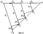
Известно (см. Л.С.Гуткин, Ю.П.Борисов, А.А.Валуев и др. Радиоуправление реактивными снарядами и космическими аппаратами./Под общ. ред. Л.С.Гуткина. М.: Сов. Радио, 1968, 680 с. и др.), что метод параллельного самонаведения боеприпаса (например, ракеты) на цель заключается в том, что вектор скорости движения ракеты (Р) в каждый момент времени направлен в упрежденную точку (А), положение которой соответствует этому моменту времени (фиг.2).It is known (see L.S. Gutkin, Yu.P. Borisov, A.A. Valuev, and others. Radio control of rockets and spacecraft. / Under the general editorship of L.S. Gutkin. M: Sov. Radio, 1968, 680 pp. And others) that the method of parallel homing of ammunition (for example, a missile) on a target is that the velocity vector of the rocket (P) at each moment of time is directed to a pre-empted point (A), the position of which corresponds to this point in time (figure 2).
На фиг.2 представлена картина взаимодействия боеприпаса (Р) и цели (Ц) в меридиональной плоскости (вдоль строительной оси боеприпаса) при самонаведении по методу параллельного сближения. При таком самонаведении вектор направления «боеприпас-цель» (РЦ) сохраняет в пространстве постоянное направление, т.е. перемещается параллельно самому себе, а измеряемое расстояние боеприпас-цель (РЦ) за одинаковое дискретное время Δt, изменяется на некоторую постоянную величину ΔR.Figure 2 presents a picture of the interaction of the ammunition (P) and the target (C) in the meridional plane (along the construction axis of the ammunition) when homing by the parallel approach method. With this homing, the direction vector “ammunition-target” (RC) maintains a constant direction in space, i.e. moves parallel to itself, and the measured distance of the ammunition target (RC) for the same discrete time Δt, changes by some constant value ΔR.
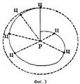
Совокупность геометрических точек, характеризующих положение цели в экваториальной плоскости (плоскости, перпендикулярной оси боеприпаса), образует вид спиральной линии (фиг.3) с центром в точке расположения боеприпаса (в точке Р). Такая форма возможного положения цели в экваториальной плоскости подтверждает возможность практической реализации метода параллельного сближения при любом пространственном взаимодействии боеприпаса и цели, что позволяет рассматривать их взаимодействие в одной, например, меридиональной плоскости, не нарушая общности принципа (см. 1) Патент №1301041 (Англия). Устройство самонаведения. МКИ F41G; 2) Патент №2325897 (Франция). Система наведения ракет. Заявл.24.09.75, опубл. 27.05.77, МКИ F41G).The set of geometric points characterizing the position of the target in the equatorial plane (the plane perpendicular to the axis of the munition), forms a spiral line (figure 3) centered at the location of the munition (at point P). This form of the possible position of the target in the equatorial plane confirms the possibility of practical implementation of the parallel approach method for any spatial interaction of the ammunition and the target, which allows us to consider their interaction in one, for example, the meridional plane, without violating the generality of the principle (see 1) Patent No. 1301041 (England ) Homing device. MKI F41G; 2) Patent No. 23235897 (France). Missile guidance system. Declared 24.09.75, publ. 05.27.77, MKI F41G).
Таким образом, при самонаведении методом параллельного сближения линия визирования (вектор расстояния РЦ=R) между боеприпасом и наблюдаемой целью при каждом текущем измерении перемещается параллельно самой себе, так что ![]()
![]()
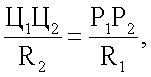
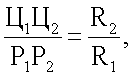
где Ц1Ц2 - расстояние между отдельными точками Ц1 и Ц2 траектории движения воздушной цели;where C 1 C 2 - the distance between the individual points of C 1 and C 2 the trajectory of the movement of an air target;
Р1Р2 - расстояние между отдельными точками Р1 и Р2 траектории движения боеприпаса.P 1 P 2 - the distance between the individual points P 1 and P 2 the trajectory of the munition.
Принимается, что для достаточно малых значений времени Δt во время самонаведения значения скоростей цели и боеприпаса остаются постоянными Vц=const и Vp=const, а измерение расстояний R1, R2, R3, …, Rn производится дискретно через равные промежутки времени Δt.It is assumed that for sufficiently small values of the time Δt during homing, the values of the target and ammunition velocities remain constant V c = const and V p = const, and the measurement of distances R 1 , R 2 , R 3 , ..., R n is carried out discretely at regular intervals time Δt.
Тогда при этих условиях расстояния, например Ц1Ц2 и Р1Р2, будут соответственно равны Ц1Ц2=VцΔt и Р1Р2=VрΔt, откудаThen, under these conditions, distances, for example, Ts 1 Ts 2 and P 1 P 2 , will respectively be equal to Ts 1 Ts 2 = V c Δt and P 1 P 2 = V p Δt, whence
![]()
![]()
Из последнего выражения следует, что при постоянстве скоростей сближения ракеты Vp=const и цели Vц=const имеет место постоянство величин отношений как измеряемых дальностейFrom the last expression it follows that with a constant velocity of approach of the rocket V p = const and the target V c = const, there is a constancy of the magnitude of relations as measured ranges
![]()
![]()
так и скоростей сближенияand approach speeds
![]()
![]()
При постоянстве скоростей ракеты и цели, естественно, будет постоянной величиной и их результирующая скорость Vрц.With a constant speed of the rocket and the target, of course, their resulting velocity V rts will also be a constant value.
Тогда имеемThen we have
![]()
![]()
где ![]()
![]()
Vсбл - радиальная составляющая вектора скорости Vрц.V sb - the radial component of the velocity vector V rts .
Тогда значение αV определяется по соотношениюThen the value of α V is determined by the relation
![]()
![]()
Таким образом, в предлагаемом устройстве самонаведения параметром рассогласования может быть выбрана одна из двух величин: либо дальномерная αR, либо скоростная αV.Thus, in the proposed homing device, the mismatch parameter can be selected one of two values: either rangefinder α R or high-speed α V.
Дальномерный параметр рассогласования αR, характеризует собой числовое значение отношения значений Ri измеренного расстояния между боеприпасом и целью в текущий момент времени ti и Ri-1 - измеренное расстояние между боеприпасом и целью в предшествующий момент времени ti-1, и определяется выражением ![]()
![]()
Параметр рассогласования по скорости сближения αV характеризует собой числовое значение отношения значений измеренных скоростей сближения боеприпаса с целью Vсбл.i в текущий момент времени ti и в предшествующий ti-1 текущему моменту времени Vсбл.i-1.The approximation mismatch parameter α V characterizes the numerical value of the ratio of the values of the measured ammunition rapprochement rates with the goal of V si at the current time t i and at the preceding t i-1 current time point V si i-1 .
Тогда параметр рассогласования αV скорости сближения в общем виде определяется выражениемThen the mismatch parameter α V of the approach speed in general is determined by the expression
![]()
![]()
Принимаем, что воздушная цель (Ц), имея сосредоточенный характер (см. Коган И.М. Ближняя радиолокация. Теоретические основы. М.: Сов. радио, 1973, 272 с.). движется со скоростью Vц, а боеприпас движется со скоростью Vp. Тогда, как отмечалось ранее, при стрельбе и точном наведении боеприпаса по методу параллельного сближения происходит контактная встреча боеприпаса с целью в некоторой упрежденной точке А (фиг.2) (или, по крайней мере, может произойти их встреча в некоторой области пространства вокруг этой точки А с допустимым минимальным радиусом дальности).We accept that the air target (C), having a concentrated character (see Kogan I.M. Near Radar. Theoretical Foundations. M: Sov. Radio, 1973, 272 p.). moves at a speed of V c , and the ammunition moves at a speed of V p . Then, as noted earlier, when firing and accurately guiding the ammunition using the parallel approach method, the ammunition comes into contact with the target at a certain anticipated point A (Fig. 2) (or, at least, they can meet in a certain area of space around this point And with a valid minimum range radius).
Дальнейшую работу предлагаемого устройства самонаведения (фиг.1) рассмотрим в двух вариантах: при измерении радиолокатором 2 дальности R и при измерении радиолокатором 2 скорости сближения Vсбл.The further work of the proposed homing device (Fig. 1) will be considered in two versions: when measuring by radar 2 of range R and when measuring by radar 2 of approach speed V sb .
Рассмотрим вариант 1.Consider option 1.
Радиолокатор 2 является измерителем дальности (дальномером).Radar 2 is a range meter (rangefinder).
В начальный момент времени t0 по внешней команде «пуск» (например, по команде от временного предохранительно-исполнительного устройства радиовзрывателя) от таймера 10 происходит измерение расстояния R0 между боеприпасом и целью радиолокатором 2. Данные этого первого измерения записывается в первом блоке памяти 3. В следующий момент времени t1 радиолокатор 2 так же измеряет расстояние между боеприпасом и целью R1, значение которого поступает как в первый блок вычисления 4, так и одновременно записывается в первом блоке памяти 3, вытесняя из него значение предыдущего расстояния R0, которое в свою очередь поступает на второй вход первого блока вычисления 4 и в котором производится вычисление отношения ![]()
![]()
Затем сигналом из первого блока вычисления 4 включается электронный ключ 5 и через него значение α1 из выхода первого блока вычисления 4 поступает на запись во второй блок памяти 6, после чего электронный ключ 5 выключается и в дальнейшей работе устройства не участвует. В последующий момент времени t2 радиолокатор 2 измеряет расстояние между боеприпасом и целью R2, которое поступает в первый блок вычисления 4, в котором определяется отношение измеренных предшествующей R1 и текущей R2 дальностей ![]()
![]()
![]()
![]()
![]()
![]()
т.е. появляется неравенствоthose. inequality appears
![]()
![]()
и при этом линии визирования ЦР между собой будут не параллельны:and while the line of sight of the CR between themselves will not be parallel:
![]()
![]()
Таким образом, в дальномерном варианте радиолокатора 2 параметром рассогласования является величина αR, характеризующая собой числовое значение отношения величины измеренного текущего расстояния Ri к значению расстояния предшествующего измерения Ri-1 Thus, in the rangefinder variant of radar 2, the mismatch parameter is α R , which characterizes the numerical value of the ratio of the measured current distance R i to the distance value of the previous measurement R i-1
![]()
![]()
Абсолютная ошибка системы самонаведения при измерении дальности, обусловленная изменением траектории движения цели или боеприпаса, будет ![]()
![]()
![]()
![]()
При безошибочном самонаведении боеприпаса по методу параллельного сближения δR=0 и Z=1.With an unmistakable homing of ammunition by the method of parallel approximation, δR = 0 and Z = 1.
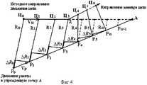
На фиг.4 показано, что если изменение траектории движения цели произошло, например, в точке Д, то при неизменной траектории движения боеприпаса (Р) относительная ошибка, начиная с этой точки (Д) не равна единице, т.е. ![]()
![]()
что и регистрируется логическим устройством (8), с которого подается сигнал рассогласования измеряемых величин на устройство управления движением боеприпаса (9). Следовательно, при измерении неравных дальностей R имеем, например, R3-R4≠R2-R3, т.e. ΔRi-1≠ΔRi, в результате чего подается команда с логического устройства (8) на устройство управления (9), изменяющая траекторию движения боеприпаса таким образом, чтобы обеспечивалось условие самонаведения по методу параллельного сближения, т.е. ΔRi-1=ΔRi.as recorded by the logical device (8), from which the signal of the mismatch of the measured values is supplied to the munition movement control device (9). Therefore, when measuring unequal ranges of R, we have, for example, R 3 -R 4 ≠ R 2 -R 3 , i.e. ΔR i-1 ≠ ΔR i , as a result of which a command is sent from the logic device (8) to the control device (9), which changes the trajectory of the munition in such a way as to ensure the homing condition by the parallel approach method, i.e. ΔR i-1 = ΔR i .
Следовательно, величины δR и Z, характеризующие ошибку траекторного наведения в i-й точке траектории, могут быть значениями, необходимыми для управления системой самонаведения. Знаки «+» или «-» при δR и величины 1<Z>1 характеризуют направление фактической траектории движения боеприпаса и цели по отношению к траектории при безошибочном (точном) наведении.Therefore, the values of δR and Z, characterizing the error of the trajectory guidance at the i-th point of the trajectory, can be the values necessary to control the homing system. The signs “+” or “-” at δR and the values 1 <Z> 1 characterize the direction of the actual trajectory of the ammunition and the target with respect to the trajectory during error-free (accurate) guidance.
Рассмотрим вариант 2.Consider option 2.
Радиолокатор 2 является измерителем скорости сближения (измерителем доплеровских частот).Radar 2 is a proximity speed meter (Doppler frequency meter).
Ранее установлено, что в качестве параметра рассогласования при самонаведении боеприпаса по методу параллельного сближения может быть скорость сближения объектов Vсбл, определяемая радиолокатором 2 через оценку частоты Доплера.It was previously established that as a parameter of the mismatch during the self-guidance of ammunition by the method of parallel approach, there can be a speed of approach of objects V sb , determined by radar 2 through an estimate of the Doppler frequency.
С учетом длины волны λ излучаемого сигнала радиолокатором 2 скорость сближения объектов Vсбл является величиной, прямопропорциональной доплеровской частоте (см. Коган И.М. Ближняя радиолокация. Теоретические основы. М.: Сов. радио, 1973, 272 с.), так чтоTaking into account the wavelength λ of the emitted signal by radar 2, the approach speed of the objects V sb is a value directly proportional to the Doppler frequency (see Kogan I.M. Near Radar. Theoretical Foundations. M: Sov. Radio, 1973, 272 pp.), So
![]()
![]()
![]()
![]()
Поэтому в предлагаемом устройстве самонаведения оценка скорости сближения, являющейся параметром рассогласования, может сводиться к определению радиолокатором 2 частоты Доплера Fд.Therefore, in the proposed homing device, an estimate of the approach speed, which is a mismatch parameter, can be reduced to determining the Doppler frequency F d by the radar 2.
При самонаведении по методу параллельного сближения и постоянстве скоростей как цели (Vц=const), так и боеприпаса (Vp=const) за равные промежутки времени Δt цель и боеприпас соответственно проходят путь:When homing by the method of parallel approach and constant speeds of both the target (V c = const) and the ammunition (V p = const) for equal time intervals Δt, the target and ammunition respectively go the way:
![]()
![]()
где i=0, 1, 2, … n, а линии визирования Ц0Ц1=Ц0Цi-1=VцΔt (фиг.5) в любые моменты времени от начала самонаведения t0 до момента встречи боеприпаса с целью будут между собой параллельны, т.е ![]()
![]()
Как видно из фиг.5 и фиг.6, скорость сближения боеприпаса с целью Vсбл определяется углом визирования β0 и суммарной скоростью «боеприпас-цель» Vрц. Если соблюдается условие постоянства скоростей движения боеприпаса и цели, тогда радиальная составляющая суммарной скорости «боеприпас-цель» Vсбл является постоянной величиной в каждой i-й точке траектории Vсбл=Vрцcosβ0=const, так как значения углов β0 между линией визирования на цель и на упрежденную точку А при всех измерениях будут равны, т.е. β0=β1=…=βn. Поэтому при самонаведении методом параллельного сближения доплеровская частота Fдi в каждой точке траектории движения боеприпаса также будет постоянной и равнойAs can be seen from figure 5 and figure 6, the convergence rate of the ammunition with a target of V sbl is determined by the angle of sight β 0 and the total velocity of “ammunition-target” V rts . If the observed condition of constant movement velocity of the munition and the target, whereas the radial component of the total velocity "ammo-purpose» V SBL is constant in each i-th point trajectory V SBL = V pq cosβ 0 = const, since the angles β 0 between the line Sights on the target and on the lead point A for all measurements will be equal, i.e. β 0 = β 1 = ... = β n . Therefore, when homing by the parallel approach method, the Doppler frequency F di at each point of the munition trajectory will also be constant and equal to

При маневре цели или боеприпаса угол визирования β0 изменяется, например, до значения βγ (фиг.6), что приведет к изменению, во-первых, результирующей скорости ракета-цель Vрц, и, во-вторых, изменится значение радиальной составляющей этой измененной скорости Vсбл, что в конечном счете приведет к изменению частоты Доплера F' дi+1.When maneuvering a target or ammunition, the viewing angle β 0 changes, for example, to β γ (Fig. 6), which will lead to a change, firstly, of the resulting velocity of the target missile V rts , and, secondly, the value of the radial component this altered speed V sb , which ultimately leads to a change in the Doppler frequency F ' di + 1 .
В этом случае величина ΔFд=Fдi-F' дi+1 является мерой рассогласования траектории движения боеприпаса, самонаводящегося по методу параллельного сближения. Тогда сигнал на выходе радиолокатора 2 характеризуется частотой Доплера. Знак «+» или In this case, the value ΔF d = F di -F ' di + 1 is a measure of the mismatch of the trajectory of the munition homing by the parallel approach method. Then the signal at the output of the radar 2 is characterized by the Doppler frequency. + Sign or
«-» при ΔFд соответствует направлению изменения траектории движения боеприпаса.“-” at ΔF d corresponds to the direction of change of the munition trajectory.
В дальнейшем при выполнении радиолокатором 2 функций измерителя доплеровских частот работа предлагаемого устройства (фиг.1) аналогична той, которая изложена ранее, при рассмотрении измерений радиолокатором 2 дальностей.Subsequently, when the radar 2 performs the functions of a Doppler frequency meter, the operation of the proposed device (Fig. 1) is similar to that described above, when considering measurements by a 2-range radar.
Рассмотренные выше два варианта работы устройства самонаведения, при которых радиолокатор 2 (фиг.1) выполняет функции дальномера или измерителя скорости сближения, свидетельствуют о том, что при использовании радиолокатора 2 в качестве дальномера или частотомера доплеровских частот функциональная работа предлагаемого устройства самонаведения в целом будет одинаковой, имея в виду, что на выходе радиолокатора 2 параметром рассогласования в дальномерном варианте является параметр дальности между боеприпасом и целью, а в частотном варианте - скорость сближения между ними.The above two options for the operation of the homing device, in which the radar 2 (Fig. 1) acts as a range finder or proximity meter, indicate that when using radar 2 as a range finder or Doppler frequency meter, the functional operation of the proposed homing device as a whole will be the same , bearing in mind that at the output of radar 2, the mismatch parameter in the rangefinder variant is the distance parameter between the ammunition and the target, and in the frequency variant e - the rate of convergence between them.
Предлагаемое устройство самонаведения методом параллельного сближения отличается от известного простотой технической реализации управления движением боеприпаса ограниченного объема.The proposed device homing parallel approach differs from the known simplicity of the technical implementation of the movement control of ammunition of a limited volume.
В боеприпасах ограниченных объемов широко применяются радиовзрыватели (см. 1) Гуткин Л.С., Борисов Ю.П., Валуев А.А. и др. Радиоуправление реактивными снарядами и космическими аппаратами./Под общ. ред. Л.С.Гуткина. М.: Сов. Радио, 1968, 680 с.; 2) Дорофеев А.Н. Взрыватели ракет. М.: Военное изд. МО СССР, 1963, 86 с.), поэтому в предлагаемом устройстве самонаведения в качестве радиолокатора 2 для оценки параметра рассогласования (дальности или скорости сближения) может быть использован радиотракт радиовзрывателя боеприпаса. Использованием, например, радиотракта импульсного или частотного радиовзрывателя радиолокатор 2 (фиг.1) может быть реализован как дальномер, а при использовании, например, радиотракта автодинного радиовзрывателя радиолокатор 2 (фиг.1) может быть реализован как измеритель скорости сближения через измерения доплеровских частот. Кроме того, применительно к боеприпасам предлагаемое устройство самонаведения позволяет использовать радиовзрыватель боеприпаса путем использования и других его элементов, таких как приемо-передающую антенна и предохранительно-исполнительный механизм (в качестве таймера).In munitions of limited volumes, radio fuses are widely used (see 1) Gutkin L.S., Borisov Yu.P., Valuev A.A. et al. Radio control of rockets and spacecraft. / Under the general. ed. L.S. Gutkina. M .: Sov. Radio, 1968, 680 p .; 2) Dorofeev A.N. Rocket fuses. M .: Military ed. Ministry of Defense of the USSR, 1963, 86 pp.), Therefore, in the proposed homing device as a radar 2 to estimate the mismatch parameter (range or approach speed), the radio path of the munition radio fuse can be used. Using, for example, a radio path of a pulsed or frequency radio fuse, radar 2 (Fig. 1) can be implemented as a range finder, and when using, for example, a radio path of an autodyne radio fuse, radar 2 (Fig. 1) can be implemented as an approach speed meter through measurements of Doppler frequencies. In addition, with regard to ammunition, the proposed homing device allows you to use a radio fuse of ammunition by using its other elements, such as a transmit-receive antenna and a safety-actuating mechanism (as a timer).
Кроме перечисленных, остальные элементы предлагаемого устройства самонаведения могут быть реализованы известными и широко применяемыми в электронных устройствах аналоговыми элементами и интегральными микросхемами (см. Интегральные микросхемы. Справочник./Под общей ред. Б.В. Тарабрина. М.: Изд. Сов. радио, 1984).In addition to the above, the remaining elements of the proposed homing device can be implemented by well-known and widely used in electronic devices analog elements and integrated circuits (see Integrated circuits. Reference. / Under the general editorship of B.V. Tarabrin. M .: Publishing house. Sov. Radio , 1984).
Введением предлагаемых элементов и связей между ними принципиально по-новому решается проблема создания устройства самонаведения летательных аппаратов ограниченных объемов.By introducing the proposed elements and the relationships between them, the problem of creating a homing device for aircraft of limited volumes is fundamentally solved in a new way.
Изготовленный макет предлагаемого устройства самонаведения применительно к реальному боеприпасу ограниченного объема класса «земля-воздух», испытанный как в лабораторных, так и в натурных полигонных условиях, показал его работоспособность при различных и случайных маневрах воздушной цели.A fabricated model of the proposed homing device as applied to real ammunition of a limited volume of ground-to-air class, tested both in laboratory and in-situ polygon conditions, showed its operability under various and random maneuvers of an air target.
Claims (1)
Priority Applications (1)
| Application Number | Priority Date | Filing Date | Title |
|---|---|---|---|
| RU2008131747/02A RU2392575C2 (en) | 2008-07-31 | 2008-07-31 | Self-homing device |
Applications Claiming Priority (1)
| Application Number | Priority Date | Filing Date | Title |
|---|---|---|---|
| RU2008131747/02A RU2392575C2 (en) | 2008-07-31 | 2008-07-31 | Self-homing device |
Publications (2)
| Publication Number | Publication Date |
|---|---|
| RU2008131747A RU2008131747A (en) | 2010-02-10 |
| RU2392575C2 true RU2392575C2 (en) | 2010-06-20 |
Family
ID=42123433
Family Applications (1)
| Application Number | Title | Priority Date | Filing Date |
|---|---|---|---|
| RU2008131747/02A RU2392575C2 (en) | 2008-07-31 | 2008-07-31 | Self-homing device |
Country Status (1)
| Country | Link |
|---|---|
| RU (1) | RU2392575C2 (en) |
Cited By (2)
| Publication number | Priority date | Publication date | Assignee | Title |
|---|---|---|---|---|
| RU2466344C1 (en) * | 2011-05-16 | 2012-11-10 | Федеральное Государственное Унитарное Предприятие "Научно-Исследовательский Институт "Экран" | Self-guidance device |
| RU2552990C1 (en) * | 2014-05-05 | 2015-06-10 | Юрий Владимирович Рябов | Method for approaching of moving object at self-guidance as per information on fact of target localisation |
Citations (4)
| Publication number | Priority date | Publication date | Assignee | Title |
|---|---|---|---|---|
| FR2517818A1 (en) * | 1981-12-09 | 1983-06-10 | Thomson Brandt | GUIDING METHOD TERMINAL AND MISSILE GUIDE OPERATING ACCORDING TO THIS METHOD |
| EP0436215A2 (en) * | 1990-01-08 | 1991-07-10 | Hughes Aircraft Company | Lightweight missile guidance system |
| RU2099665C1 (en) * | 1995-06-19 | 1997-12-20 | Военная академия противовоздушной обороны им.маршала Советского Союза Жукова Г.К. | Method of generation of air-to-air missile control signal and device for its realization |
| RU2189556C2 (en) * | 1999-11-26 | 2002-09-20 | Калинкин Виктор Алексеевич | Method for formation of flight vehicle control signals at homing on air target |
-
2008
- 2008-07-31 RU RU2008131747/02A patent/RU2392575C2/en not_active IP Right Cessation
Patent Citations (4)
| Publication number | Priority date | Publication date | Assignee | Title |
|---|---|---|---|---|
| FR2517818A1 (en) * | 1981-12-09 | 1983-06-10 | Thomson Brandt | GUIDING METHOD TERMINAL AND MISSILE GUIDE OPERATING ACCORDING TO THIS METHOD |
| EP0436215A2 (en) * | 1990-01-08 | 1991-07-10 | Hughes Aircraft Company | Lightweight missile guidance system |
| RU2099665C1 (en) * | 1995-06-19 | 1997-12-20 | Военная академия противовоздушной обороны им.маршала Советского Союза Жукова Г.К. | Method of generation of air-to-air missile control signal and device for its realization |
| RU2189556C2 (en) * | 1999-11-26 | 2002-09-20 | Калинкин Виктор Алексеевич | Method for formation of flight vehicle control signals at homing on air target |
Cited By (2)
| Publication number | Priority date | Publication date | Assignee | Title |
|---|---|---|---|---|
| RU2466344C1 (en) * | 2011-05-16 | 2012-11-10 | Федеральное Государственное Унитарное Предприятие "Научно-Исследовательский Институт "Экран" | Self-guidance device |
| RU2552990C1 (en) * | 2014-05-05 | 2015-06-10 | Юрий Владимирович Рябов | Method for approaching of moving object at self-guidance as per information on fact of target localisation |
Also Published As
| Publication number | Publication date |
|---|---|
| RU2008131747A (en) | 2010-02-10 |
Similar Documents
| Publication | Publication Date | Title |
|---|---|---|
| US8587473B2 (en) | System and method for roll angle indication and measurement in flying objects | |
| US8146401B2 (en) | Method and apparatus for in-flight calibration of gyroscope using magnetometer reference | |
| US3982246A (en) | General method of geometrical passive ranging | |
| US8093539B2 (en) | Integrated reference source and target designator system for high-precision guidance of guided munitions | |
| KR101560580B1 (en) | Navigation apparatus for projectiles and control method thereof | |
| US11815335B2 (en) | Guided munition systems for detecting off-axis targets | |
| US3301508A (en) | Guidance system with stellar correction | |
| US2995318A (en) | Optical data transfer system | |
| US8076621B2 (en) | Integrated reference source and target designator system for high-precision guidance of guided munitions | |
| Vergez et al. | Optimal control and estimation for strapdown seeker guidance of tactical missiles | |
| US8637798B2 (en) | Integrated reference source and target designator system for high-precision guidance of guided munitions | |
| RU2392575C2 (en) | Self-homing device | |
| US3699310A (en) | Angular rate bombing system | |
| RU2728197C1 (en) | Method to control a group of unmanned aerial vehicles taking into account the degree of danger of surrounding objects | |
| Baqar | Low-cost PC-based high-fidelity infrared signature modelling and simulation | |
| Abruzzo et al. | Online calibration of inertial sensors for range correction of spinning projectiles | |
| RU2170907C1 (en) | Method for aiming in attack of high-speed targets by fighter in flat trajectory and device for its realization | |
| RU2466344C1 (en) | Self-guidance device | |
| RU2539823C1 (en) | Method of self-guidance of small-sized missiles to target and system for its implementation | |
| US4202516A (en) | Electronic tripod technique | |
| US4306691A (en) | Stellar corrector | |
| Hablani | Autonomous relative navigation, attitude determination, pointing and tracking for spacecraft rendezvous | |
| US3328881A (en) | Rapid inertial alignment method | |
| US8513580B1 (en) | Targeting augmentation for short-range munitions | |
| RU2539824C1 (en) | Small-size aircraft target homing system |
Legal Events
| Date | Code | Title | Description |
|---|---|---|---|
| MM4A | The patent is invalid due to non-payment of fees |
Effective date: 20110801 |