RU2388024C2 - Shielded pressure-pads for detection of underground radiation phenomena - Google Patents
Shielded pressure-pads for detection of underground radiation phenomena Download PDFInfo
- Publication number
- RU2388024C2 RU2388024C2 RU2006105519/28A RU2006105519A RU2388024C2 RU 2388024 C2 RU2388024 C2 RU 2388024C2 RU 2006105519/28 A RU2006105519/28 A RU 2006105519/28A RU 2006105519 A RU2006105519 A RU 2006105519A RU 2388024 C2 RU2388024 C2 RU 2388024C2
- Authority
- RU
- Russia
- Prior art keywords
- pressure shoe
- recess
- radiation
- shielding material
- detector
- Prior art date
Links
Images


Classifications
-
- G—PHYSICS
- G01—MEASURING; TESTING
- G01V—GEOPHYSICS; GRAVITATIONAL MEASUREMENTS; DETECTING MASSES OR OBJECTS; TAGS
- G01V5/00—Prospecting or detecting by the use of nuclear radiation, e.g. of natural or induced radioactivity
- G01V5/04—Prospecting or detecting by the use of nuclear radiation, e.g. of natural or induced radioactivity specially adapted for well-logging
- G01V5/08—Prospecting or detecting by the use of nuclear radiation, e.g. of natural or induced radioactivity specially adapted for well-logging using primary nuclear radiation sources or X-rays
- G01V5/10—Prospecting or detecting by the use of nuclear radiation, e.g. of natural or induced radioactivity specially adapted for well-logging using primary nuclear radiation sources or X-rays using neutron sources
- G01V5/101—Prospecting or detecting by the use of nuclear radiation, e.g. of natural or induced radioactivity specially adapted for well-logging using primary nuclear radiation sources or X-rays using neutron sources and detecting the secondary Y-rays produced in the surrounding layers of the bore hole
-
- G—PHYSICS
- G01—MEASURING; TESTING
- G01V—GEOPHYSICS; GRAVITATIONAL MEASUREMENTS; DETECTING MASSES OR OBJECTS; TAGS
- G01V5/00—Prospecting or detecting by the use of nuclear radiation, e.g. of natural or induced radioactivity
- G01V5/04—Prospecting or detecting by the use of nuclear radiation, e.g. of natural or induced radioactivity specially adapted for well-logging
- G01V5/08—Prospecting or detecting by the use of nuclear radiation, e.g. of natural or induced radioactivity specially adapted for well-logging using primary nuclear radiation sources or X-rays
- G01V5/10—Prospecting or detecting by the use of nuclear radiation, e.g. of natural or induced radioactivity specially adapted for well-logging using primary nuclear radiation sources or X-rays using neutron sources
- G01V5/107—Prospecting or detecting by the use of nuclear radiation, e.g. of natural or induced radioactivity specially adapted for well-logging using primary nuclear radiation sources or X-rays using neutron sources and detecting reflected or back-scattered neutrons
-
- G—PHYSICS
- G01—MEASURING; TESTING
- G01V—GEOPHYSICS; GRAVITATIONAL MEASUREMENTS; DETECTING MASSES OR OBJECTS; TAGS
- G01V5/00—Prospecting or detecting by the use of nuclear radiation, e.g. of natural or induced radioactivity
- G01V5/04—Prospecting or detecting by the use of nuclear radiation, e.g. of natural or induced radioactivity specially adapted for well-logging
- G01V5/08—Prospecting or detecting by the use of nuclear radiation, e.g. of natural or induced radioactivity specially adapted for well-logging using primary nuclear radiation sources or X-rays
- G01V5/12—Prospecting or detecting by the use of nuclear radiation, e.g. of natural or induced radioactivity specially adapted for well-logging using primary nuclear radiation sources or X-rays using gamma or X-ray sources
- G01V5/125—Prospecting or detecting by the use of nuclear radiation, e.g. of natural or induced radioactivity specially adapted for well-logging using primary nuclear radiation sources or X-rays using gamma or X-ray sources and detecting the secondary gamma- or X-rays in different places along the bore hole
Abstract
Description
Изобретение относится к скважинному устройству для определения свойств подземных формаций. В частности, изобретение относится к способам и устройству для детектирования явлений подземного излучения.The invention relates to a downhole device for determining the properties of underground formations. In particular, the invention relates to methods and apparatus for detecting underground radiation phenomena.
Уровень техникиState of the art
Характеристики геологических формаций представляют собой значительный интерес при разведке и добыче подземных горизонтов воды и месторождений минералов, например нефти и газа. Многие характеристики, такие как объем углеводородов, пористость, литология и проницаемость формации, можно вывести из некоторых измеряемых величин. В числе этих величин: плотность, пористость по данным нейтронного каротажа, фотоэлектрический коэффициент (Ре), водородный индекс, соленость и сечение захвата тепловых нейтронов («Сигма»). Эти величины обычно измеряют инструментами каротажа во время бурения и спускаемыми на тросе инструментами. В обычном инструменте имеется источник, который излучает энергию в формацию, и один или несколько детекторов, которые определяют получающееся взаимодействие излучения. Данные об обнаруженном сигнале обычно передают на поверхность, временно запоминают в скважине для последующей обработки либо эти способы комбинируют для определения характеристик геологической формации, из которой эти данные были собраны.The characteristics of geological formations are of significant interest in the exploration and production of underground water horizons and mineral deposits, such as oil and gas. Many characteristics, such as hydrocarbon volume, porosity, lithology, and formation permeability, can be deduced from some measured values. Among these values are: density, porosity according to neutron logging, photoelectric coefficient (Fe), hydrogen index, salinity and thermal neutron capture cross section (Sigma). These values are usually measured with logging tools while drilling and wireline tools. A conventional tool has a source that radiates energy to the formation, and one or more detectors that determine the resulting radiation interaction. Data on the detected signal is usually transmitted to the surface, temporarily stored in the well for subsequent processing, or these methods are combined to determine the characteristics of the geological formation from which this data was collected.
Из числа многих представляющих интерес величин при разведке и добыче углеводородов наиболее важными являются: плотность и фотоэлектрический коэффициент формации. Эти величины обычно измеряют инструментом, имеющим источник гамма-излучения и по меньшей мере один детектор гамма-излучения (см., напр., патенты США №№5,390,115; 5,596,142; 6,376,838; 5,528,029; 4,691,102). Глубина исследования при помощи этого измерения относительно неглубокая - порядка нескольких сантиметров. Следовательно, данный тип измерения чувствителен к среде вблизи корпуса инструмента. В частности, буровой раствор (глина) или глинистая корка между инструментом и формацией ухудшают точность измерения.Of the many quantities of interest in the exploration and production of hydrocarbons, the most important are: density and photoelectric coefficient of the formation. These values are usually measured with an instrument having a gamma radiation source and at least one gamma radiation detector (see, for example, US Pat. Nos. 5,390,115; 5,596,142; 6,376,838; 5,528,029; 4,691,102). The depth of research using this measurement is relatively shallow - on the order of a few centimeters. Therefore, this type of measurement is sensitive to the environment near the tool body. In particular, drilling mud (clay) or clay cake between the tool and the formation impairs the accuracy of the measurement.
Для снижения воздействия со стороны этих эффектов среды источник и детектор(ы) гамма-излучения обычно в значительной степени экранируют и коллимируют. Помимо этого два детектора гамма-излучения обычно находятся в инструменте. Отстоящий от источника детектор обычно используют для первичного измерения плотности, и один детектор, расположенный ближе к источнику, используется для поправки на эффекты, действующие близко к инструменту. Для инструментов радиоактивного каротажа, доставляемых в формацию на бурильной трубе, эти методы по существу являются единственными, которые можно применить для повышения точности измерения.To reduce the effects of these environmental effects, the source and detector (s) of gamma radiation are usually substantially screened and collimated. In addition, two gamma-ray detectors are usually located in the instrument. A detached detector is typically used for primary density measurements, and one detector located closer to the source is used to correct for effects that are close to the instrument. For radioactive logging tools delivered to a formation on a drill pipe, these methods are essentially the only ones that can be used to improve measurement accuracy.
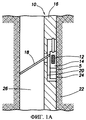
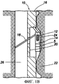
Но существуют дополнительные способы для сведения к минимуму разделенности между инструментом и формацией для инструментов, вводимых через формацию при помощи троса, подъемного стропа, разматываемых трубок, устройств для позиционирования инструмента или через бурильную трубу. Этот способ показан на Фиг.1А. Согласно этому способу источник 5 (например, источник гамма-излучения) и один или несколько детекторов 12 установлены в прижимном башмаке 14. Этот прижимной башмак 14 обычно соединен шарнирным соединением с несущим элементом или основным корпусом 16 инструмента 10 согласно известному уровню техники. Механическое и электрическое обеспечение для прижимного башмака 14 обеспечено в корпусе инструмента, и в самом прижимном башмаке участок этого обеспечения называют С-образным углублением 20 по форме его поперечного сечения (см. Фиг.2А). Отклоняющий или подпирающий рычаг 18 прикреплен сзади прижимного башмака 14 и используется для отведения его от основного корпуса 16 и в контакт с формацией 22.But there are additional ways to minimize the separation between the tool and the formation for tools inserted through the formation using a cable, a lifting sling, unwinding tubing, tool positioning devices, or through a drill pipe. This method is shown in FIG. 1A. According to this method, a source 5 (for example, a gamma radiation source) and one or
Согласно Фиг.1А и 1В во время выполнения каротажа подпирающий рычаг 18 принудительно вводит открытую поверхность 24 прижимного башмака 14 в контакт со стенкой ствола 26 скважины. На чертеже Фиг.1А ствол 26 скважины показан ровным, и прижимной башмак 14 расположен внутри углубления 20. На Фиг.1В ствол скважины является размытым, и прижимной башмак 14 выдвинут в углубление 20.1A and 1B, while logging is performed, the
Такая компоновка позволяет источнику 5 и детектору(ам) 12 оставаться вблизи формации 22 в разных условиях. В гладком стволе 26 скважины без глинистой корки (Фиг.1А и 2А) прижимной башмак 14 контактирует с формацией 22 и помещен внутри углубления 20. В вымытых или неровных стволах 26 скважины (Фиг.1В и 2В) прижимной башмак 14 продолжает контактировать с формацией 22, но теперь он выдвинут из углубления 20. Если бы детектор(ы) 12 находился внутри корпуса 16 инструмента, то между инструментом 10 и формацией 22 в этом случае находилось значительное количество глинистой корки, и это было бы причиной возможного ухудшения измерения.Such an arrangement allows
Хотя применение инструмента на прижимном башмаке уменьшает трудность обеспечения хорошего контакта между инструментом и формацией в не идеальных ситуациях, оно сопряжено с возможными затруднениями. Плотность и Ре (технические характеристики) формации обычно измеряют путем контролирования изменений количества и распределения детектированных гамма-лучей, исходя из того предположения, что эти изменения возникают только из изменений в свойствах формации или глинистой корки, или в зазоре между инструментом и стенкой ствола скважины. Сравнение Фиг.2А и 2В показывает еще одно последствие, которое может обусловить изменение детектируемого излучения в положении прижимного башмака 14 относительно углубления 20. Это положение изменяется динамически во время каротажа скважины не только по причине вымытых участков и неровностей, но также и в связи с точностью сочленения и способом транспортирования инструмента, и с траекторией ствола скважины. Если последствие этого изменения значительное и нескорректированное, то оно обусловит погрешность измерения.Although the use of the tool on the pressure shoe reduces the difficulty of ensuring good contact between the tool and the formation in not ideal situations, it is fraught with possible difficulties. The density and Pe (technical characteristics) of the formation is usually measured by monitoring changes in the quantity and distribution of detected gamma rays, based on the assumption that these changes arise only from changes in the properties of the formation or clay cake, or in the gap between the tool and the borehole wall. A comparison of FIGS. 2A and 2B shows another consequence that may cause a change in the detected radiation in the position of the
Эта ошибка, вероятно, будет крупнее при наличии имеющих меньшую плотность скважинных флюидов. Излучение, взаимодействующее с углублением в некоторой точке при перемещении от источника 5 к детектору 12, обусловит точность измерения в зависимости от положения углубления 20. Для достижения углубления 20 эти гамма-лучи должны обязательно пройти через ствол скважины 26. Большее их ослабление является вероятным в стволах скважины, наполненных более плотной текучей средой по сравнению с менее плотной текучей средой, и поэтому этот эффект наличия углубления будет, как правило, более значительным в последнем случае. В частности, действие используемых с прижимным башмаком чувствительных к излучению измерительных инструментов в заполненных воздухом скважинах подвержено этой проблеме в особой степени.This error is likely to be larger in the presence of lower density well fluids. The radiation interacting with the recess at some point when moving from the
Устройства радиоактивного каротажа предыдущего поколения использовали массивное экранирование. Это экранирование предназначалось для ограничения детектируемого излучения (например, гамма-лучей) излучением, проходящим в основном в формации близко к линии наибольшего приближения между инструментом и формацией. Результат: измерение, более сфокусированное, и менее чувствительное к диаметру ствола скважины и к скважинному флюиду.Previous generation radioactive logging devices used massive shielding. This shielding was intended to limit the detected radiation (for example, gamma rays) to radiation passing mainly in the formation close to the line of closest approximation between the instrument and the formation. Result: a measurement that is more focused and less sensitive to borehole diameter and to wellbore fluid.
Эти способы обычного экранирования выполняют свое назначение, но с некоторыми недостатками. Для эффективного ослабления нежелательного излучения экранирующие материалы должны содержать элементы с большим атомным числом и с высокой плотностью. Помимо этого для энергий присутствующего излучения и для чувствительности (точности) измерения требуется, чтобы экранирование было большой толщины. Экранирующие материалы к тому же трудно формировать и подвергать машинной обработке, и мало кто из изготовителей соглашается на это. В силу этих особенностей получаются очень крупные, тяжелые и дорогостоящие инструменты.These conventional shielding methods fulfill their purpose, but with some drawbacks. To effectively reduce unwanted radiation, shielding materials must contain elements with a large atomic number and high density. In addition, for the energies of the radiation present and for the sensitivity (accuracy) of the measurement, shielding is required to be large. Shielding materials are also difficult to shape and machine, and few manufacturers agree to this. Due to these features, very large, heavy and expensive tools are obtained.
С другой стороны, часто требуется, чтобы обычные скважинные инструменты были небольшими, легкими и недорогими. При этом пространство, имеющееся для экранирования, ограничивается в еще большей степени. Причем измерение обязательно будет менее сфокусированным, и возможно, что на измерении скажется положение углубления, если не будут приняты дополнительные меры. Это подтверждается вычислениями атомного моделирования. Например, для прижимного башмака в заполненном воздухом стволе скважины кажущаяся плотность может изменяться на ~0,1 г/см3 с относительным положением прижимного башмака и углубления, т.е. почти в десять раз больше требуемой точности ~0,1 г/см3.On the other hand, it is often required that conventional downhole tools are small, light and inexpensive. At the same time, the space available for shielding is even more limited. Moreover, the measurement will necessarily be less focused, and it is possible that the position of the recess will affect the measurement if additional measures are not taken. This is confirmed by atomic modeling calculations. For example, for a pressure shoe in an air-filled wellbore, the apparent density can vary by ~ 0.1 g / cm 3 with the relative position of the pressure shoe and recess, i.e. almost ten times greater than the required accuracy of ~ 0.1 g / cm 3 .
Продолжает оставаться необходимость обеспечения усовершенствованных способом экранирования инструмента радиоактивного каротажа для уменьшения нежелательных воздействий на измерения.There remains a need to provide an improved method for shielding a radioactive logging tool to reduce unwanted effects on measurements.
Сущность изобретенияSUMMARY OF THE INVENTION
Изобретение обеспечивает устройство для детектирования явлений подземного излучения. Устройство содержит удлиненный опорный элемент, размещаемый в стволе скважины, проходящем через подземную формацию; при этом опорный элемент имеет углубление вдоль его продольной оси; прижимной башмак, связанный с опорным элементом, причем прижимной башмак имеет поверхность, форма которой соответствует ее прилеганию к углублению в несущем элементе; причем прижимной башмак выполнен с возможностью перемещения в и из углубления, чтобы открытая поверхность прижимного башмака могла выдвигаться из опорного элемента; по меньшей мере один детектор радиоактивного излучения, расположенный внутри прижимного башмака, и прижимной башмак имеет экранирующий материал на его сторонах вблизи открытой поверхности, чтобы излучение, отражаемое от углубления, не могло доходить по меньшей мере до одного детектора из зоны вблизи открытой поверхности.The invention provides a device for detecting phenomena of underground radiation. The device comprises an elongated support element located in the wellbore passing through the underground formation; wherein the support element has a recess along its longitudinal axis; a pressure shoe associated with the support element, wherein the pressure shoe has a surface whose shape corresponds to its abutment to the recess in the bearing element; moreover, the pressure shoe is arranged to move into and out of the recess, so that the open surface of the pressure shoe can be extended from the support element; at least one radiation detector located inside the clamping shoe and the clamping shoe has shielding material on its sides near the open surface so that the radiation reflected from the recess cannot reach at least one detector from the area near the open surface.
Изобретение обеспечивает способ для детектирования явлений подземного излучения. Согласно этому способу помещают удлиненный опорный элемент в стволе скважины, проходящем через подземную формацию, причем опорный элемент имеет углубление вдоль его продольной оси и связанный с ним прижимной башмак, при этом прижимной башмак имеет поверхность с формой, сообразной для прилегания к углублению, и поверхность, открытую к стволу скважины; при этом прижимной башмак имеет по меньшей мере один детектор радиоактивного излучения, находящийся на нем и имеющий экранирующий материал на его сторонах вблизи открытой поверхности, предотвращающий прохождение отраженного от углубления излучения по меньшей мере до одного детектора из зоны вблизи открытой поверхности; активируют прижимной башмак, перемещая его в и из углубления, чтобы устанавливать открытую поверхность прижимного башмака внутри ствола скважины; и детектируют явления излучения, по меньшей мере, одним детектором.The invention provides a method for detecting underground radiation phenomena. According to this method, an elongated support element is placed in the wellbore passing through the subterranean formation, wherein the support element has a recess along its longitudinal axis and a pressure shoe associated with it, wherein the pressure shoe has a surface with a shape consistent with the recess, and a surface, open to the wellbore; wherein the pressure shoe has at least one radioactive radiation detector located on it and having a shielding material on its sides near the open surface, preventing the passage of radiation reflected from the recess to at least one detector from the area near the open surface; activating the pressure shoe by moving it into and out of the recess to establish the open surface of the pressure shoe inside the wellbore; and detecting radiation phenomena by at least one detector.
Краткое описание чертежейBrief Description of the Drawings
Прочие аспекты и преимущества изобретения станут очевидными из приводимого ниже подробного описания со ссылкой на чертежи, на которых:Other aspects and advantages of the invention will become apparent from the following detailed description with reference to the drawings, in which:
Фиг.1А схематически изображает обычный скважинный инструмент, имеющий прижимной башмак с компоновки источника-детектора ядерного излучения.Fig. 1A schematically depicts a conventional downhole tool having a pressure shoe from a layout of a nuclear radiation detector source.
Фиг.1В схематически изображает скважинный инструмент, согласно Фиг.1А; прижимной башмак показан выдвинутым в упор к стенке ствола скважины в подземной формации.Figv schematically depicts a downhole tool according to Figa; the pressure shoe is shown extended against the wall of the wellbore in the subterranean formation.
Фиг.2А показывает вид сверху обычного скважинного инструмента с прижимным башмаком, расположенным внутри углубления в корпусе инструмента.2A shows a top view of a conventional downhole tool with a pressure shoe located inside a recess in the tool body.
Фиг.2В показывает вид сверху инструмента согласно Фиг.2А; прижимной башмак выдвинут из корпуса инструмента в сторону подземной формации.Fig. 2B shows a top view of the tool of Fig. 2A; the pressure shoe is pulled out of the tool body toward the underground formation.
Фиг.3 показывает вид сверху варианта осуществления компоновки источника-детектора ядерного излучения, имеющего экранирование в соответствии с вариантом осуществления настоящего изобретения.FIG. 3 shows a top view of an embodiment of a layout of a nuclear radiation detector source having shielding in accordance with an embodiment of the present invention.
Фиг.4 показывает вид сверху варианта осуществления компоновки источник-детектор ядерного излучения, имеющего экранирование в соответствии с еще одним вариантом осуществления настоящего изобретения.FIG. 4 shows a top view of an embodiment of a nuclear radiation source-detector arrangement having shielding in accordance with yet another embodiment of the present invention.
Фиг.5 показывает вид сверху варианта осуществления экранированного прижимного башмака, расположенного в опорной конструкции, формирующей углубление в соответствии с вариантом осуществления настоящего изобретения.5 shows a top view of an embodiment of a shielded pressure shoe located in a support structure forming a recess in accordance with an embodiment of the present invention.
Подробное описаниеDetailed description
В этом изобретении экранирующий материал расположен на прижимном башмаке инструмента и препятствует основной части излучения (например, гамма-лучей), создающей эффект, обусловленный наличием углубления, достичь детектора(ов) в измерительном прижимном башмаке. В сочетании с хорошо известными из уровня техники устройствами внутреннего экранирования/коллимирования излагаемые здесь варианты осуществления экранирования прижимного башмака снижают этот эффект до приемлемого уровня. В данном описании термин «углубление» включает в себя, например, полость, выемку, камеру, отверстие либо зазор, сформированный соответствующей опорной конструкцией. Фактически, термин «углубление» может включать в себя любую конструкцию, которая, будучи в составе измерительного прижимного башмака, может создавать нежелательные эффекты, обусловленные наличием углубления, описываемые здесь.In this invention, the shielding material is located on the pressure shoe of the tool and prevents the main part of the radiation (for example, gamma rays), which creates the effect due to the presence of a recess, to reach the detector (s) in the measuring pressure shoe. In combination with internal shielding / collimating devices well known in the art, the shielding options for shielding the shoe described herein reduce this effect to an acceptable level. As used herein, the term “recess” includes, for example, a cavity, a recess, a chamber, a hole, or a gap formed by a corresponding support structure. In fact, the term “recess” may include any structure that, as part of the measuring pressure shoe, may produce undesirable effects due to the presence of the recess described herein.
Фиг.3 показывает вид сверху варианта осуществления прижимного башмака 14 согласно настоящему изобретению. Для ясности: на Фиг.3 и 4 показаны не все признаки компоновки инструмента. Специалисту в данной области техники будет ясна конфигурация этого устройства. Две полосы экранирующего материала 28 помещены на сторонах прижимного башмака 14 в направлении к формации 22. Можно использовать любой целесообразный экранирующий материал, известный из уровня техники. Предпочтительный экранирующий материал имеет высокое содержание вольфрама, является химически стойким к коррозии в возникающей от воздействия флюидов, которые могут находиться в стволе скважины. Экранирующий материал 28 проходит от формации 22 назад к оси прижимного башмака 14, в результате чего излучение, рассеиваемое из углубления 20, попадает в экранирование, до того, как достигнет фронтальной зоны открытой поверхности 24 и находящегося внутри детектора 12. Таким образом, экранирующий материал 28 предотвращает рассеяние нежелательных гамма-лучей, например, в детектор 12, делая углубление 20 по сути невидимым. В некоторых вариантах осуществления экранирующий материал можно также сформировать из материала или из комбинации материалов, способных поглощать попадающее на них излучение (например, гамма-лучи и/или нейтроны). Экранирующий материал 28 наиболее эффективен вблизи детектора 12, и поэтому длину экранирования вдоль продольной оси прижимного башмака 14 по желанию можно ограничить несколькими сантиметрами над и под детектором 12.FIG. 3 shows a top view of an embodiment of a
Боковые экранирования 28 можно прикрепить к прижимному башмаку 14 любыми соответствующими способами, включая крепежные средства, клеи, эпоксидные смолы, сварку и/или соединения ласточкиным хвостом. Дополнительные экранирующие/коллимирующие средства, которые можно расположить на прижимном башмаке 14 рядом с детектором 12, не показаны для ясности пояснения. Специалистам в данной области техники также будет ясно, что настоящее изобретение может иметь варианты осуществления с источником, расположенным на прижимном башмаке 14, на корпусе 16 инструмента или в ином месте в стволе скважины 26 согласно известному уровню техники (не показано).Side shields 28 can be attached to pressure
Фиг.4 показывает еще один вариант осуществления настоящего изобретения. В этом варианте осуществления экранирующий материал 28 расположен по сторонам прижимного башмака 14, но все же по направлению к формации 22. Экранирующий материал 26 расположен таким образом, что заменяет области углубления 20, которые в ином случае будут рассеивать излучение в сторону детектора 12. Экранирование 28 поглощает значительную часть излучения. Некоторая часть излучения может рассеиваться с бокового экранирования 28 и достигать детектора 12, но величина этого сигнала не зависит от положения углубления 20. Физика процесса этого варианта осуществления может несколько отличаться от варианта осуществления согласно Фиг.3, в котором излучение, уже рассеявшееся из углубления 20, поглощается или рассеивается до того, как достигнет детектора 12. Изменение кажущегося измеренного сигнала излучения в детекторе 12 при перемещении прижимного башмака 14 относительно углубления 20 поэтому значительно уменьшается. В обычном прижимном башмаке вычисления конфигураций экранирования согласно настоящему изобретению указывают, что чувствительность (точность) измерений кажущегося излучения (например, плотности) по отношению к положению углубления 20 можно снизить втрое по сравнению с конфигурацией без бокового экранирования 28.Figure 4 shows another embodiment of the present invention. In this embodiment, the shielding
Конфигурации экранирования 28 согласно настоящему изобретению могут содержать сплошной экранирующий материал либо могут быть выполнены из других соответствующих материалов (например, из стали, титановых сплавов, стекловолокна, полиэфирэфиркетона (РЕЕК™)) с тонким слоем экранирующего материала, расположенного на них (не показан). Эти варианты осуществления могут упростить изготовление прижимного башмака 14, т.к. для формирования заготовки прижимного башмака, на которую экранирующий материал можно нанести распылением, химическим осаждением или в виде покрытия, применимы методы экструзии и сварки. Как упоминалось выше, предпочтительный экранирующий материал 28 имеет высокое содержание вольфрама и является химически стойким к коррозии, находясь в среде скважинных флюидов. Как и в варианте осуществления согласно Фиг.3 осевая протяженность бокового экранирующего материала 28 может быть локализована вокруг используемого детектора(ов) 12. Следует отметить, что углубление 20 можно выполнить из одного или нескольких опорных элементов, которые обеспечивают механическое и/или электрическое обеспечение для корпуса инструмента вокруг прижимного башмака 14 и в которое прижимной башмак можно поместить без необходимости обеспечения С-образного поперечного сечения или без точного соответствия форме поперечного сечения прижимного башмака. Фиг.5 показывает экранированный прижимной башмак 14 согласно изобретению, расположенный в опорной конструкции, выполненной в скважинном инструменте (не показан). Согласно Фиг.5 прижимной башмак 14 может располагаться в углублении, сформированном несколькими параллельными опорными элементами 16.The shielding
Способ детектирования явлений подземного излучения согласно описываемым здесь вариантам осуществления экранирования предполагает расположение удлиненного опорного элемента 16 в стволе скважине 26, проходящем по подземной формации 22, при этом опорный элемент имеет углубление 20 вдоль продольной оси и связанный с ним прижимной башмак 14 согласно известному уровню техники. Прижимной башмак 14 имеет поверхность, форма которой соответствует прилеганию к углублению 20, и поверхность 24, открытую к стволу скважины 26. При этом прижимной башмак 14 имеет по меньшей мере один детектор 12 излучения, расположенный на нем и имеющий экранирующий материал 28 на своих сторонах вблизи открытой поверхности 24, чтобы предотвратить прохождение излучения, отраженного от углубления 20, по меньшей мере до одного детектора из области вблизи открытой поверхности. Затем прижимной башмак активируют и перемещают в углубление или из него, чтобы установить открытую поверхность прижимного башмака внутри ствола скважин для детектирования явлений излучения детектором.The method for detecting underground radiation phenomena according to the shielding options described herein involves arranging an
Несмотря на то, что способы и устройство настоящего изобретения изложены как определенные варианты осуществления, специалистам в данной области техники будет ясно, что в рамках объема раскрываемого здесь изобретения можно легко выполнить и другие варианты осуществления. Например, поскольку варианты осуществления бокового экранирования 28 могут находиться вблизи отдельного детектора 12, поэтому тот же способ можно использовать для любого числа детекторов в том же прижимном башмаке 14. Для использования с гамма-лучами излучение можно получить из любого источника происхождения. Гамма-лучи могут происходить из химического или электронного источника (такого, как генератор рентгеновских лучей) в прижимном башмаке, из природной радиоактивности в формации, или при захвате, или неупругом рассеянии нейтронов. Инструмент с нейтронным источником или нейтронными детекторами можно также выполнить с вариантами осуществления экранирования 28, раскрываемыми в настоящем изобретении. В этих вариантах осуществления боковое экранирование 28 будет выполнено из материалов экранирования нейтронов. Можно использовать большой перечень соответствующих материалов, известных из уровня техники. Материалы этого перечня включают в себя сплавы с высоким содержанием вольфрама, каучуки, каучуки, содержащие такие поглощающие нейтроны элементы, как бор, и металлические гидриды. Вольфрам является предпочтительным материалом, имеющим высокую плотность для экранирования гамма-лучей, но можно также использовать и другие целесообразные материалы, имеющие высокую плотность и соответствующее атомное число (например, уран). Специалистам в данной области техники также будет ясно, что традиционные устройства и компоненты можно использовать для реализации скважинных инструментов, содержащих варианты осуществления экранированного прижимного башмака согласно настоящему изобретению.Although the methods and apparatus of the present invention are set forth as specific embodiments, it will be apparent to those skilled in the art that other embodiments can be readily accomplished within the scope of the invention disclosed herein. For example, since the
Claims (11)
опорный элемент (16), выполненный с возможностью его размещения в стволе скважины, проходящем по подземной формации (22);
причем упомянутый опорный элемент имеет углубление (20), расположенное вдоль его продольной оси;
прижимной башмак (14), связанный с опорным элементом, при этом упомянутый прижимной башмак имеет поверхность, форма которой соответствует прилеганию к углублению в упомянутом опорном элементе;
причем прижимной башмак выполнен с возможностью перемещения в упомянутое углубление и из него таким образом, что открытая поверхность упомянутого прижимного башмака может проходить от упомянутого несущего элемента;
по меньшей мере один детектор (12) излучения, расположенный в упомянутом прижимном башмаке,
отличающееся тем, что упомянутый прижимной башмак имеет экранирующий материал (28) на его сторонах вблизи открытой поверхности, чтобы препятствовать прохождению отраженного от упомянутого углубления излучения по меньшей мере к одному детектору от зоны вблизи упомянутой открытой поверхности.1. Device for detecting the phenomena of underground radiation, containing
supporting element (16), made with the possibility of its placement in the wellbore, passing along the underground formation (22);
moreover, said supporting element has a recess (20) located along its longitudinal axis;
a pressure shoe (14) associated with the support element, wherein said pressure shoe has a surface whose shape corresponds to the abutment in the recess in said support element;
moreover, the pressure shoe is arranged to move into and out of said recess in such a way that the open surface of said pressure shoe can extend from said carrier element;
at least one radiation detector (12) located in said pressure shoe,
characterized in that said clamping shoe has a shielding material (28) on its sides near an open surface in order to prevent radiation reflected from said recess from at least one detector from an area close to said open surface.
отличающийся тем, что прижимной башмак имеет экранирующий материал (28) на его сторонах вблизи открытой поверхности, чтобы препятствовать прохождению отраженного от углубления излучения по меньшей мере до одного детектора из области вблизи упомянутой открытой поверхности; активируют прижимной башмак, перемещая его в и из углубления, чтобы устанавливать открытую поверхность прижимного башмака внутри ствола скважины, и детектируют явления излучения по меньшей мере одним детектором. 11. A method for detecting the phenomena of underground radiation, according to which an elongated support element (16) is placed in the wellbore passing through the underground formation (22), the support element having a recess (20) along its longitudinal axis and a pressure shoe associated with it, the pressure shoe has a surface with a shape for abutment to the said recess and the surface open to the wellbore, while the pressure shoe has at least one radiation detector (12) located on it,
characterized in that the pressure shoe has a shielding material (28) on its sides near the open surface, in order to prevent the radiation reflected from the recess from reaching at least one detector from an area near said open surface; activating the pressure shoe by moving it to and from the recess to establish an open surface of the pressure shoe inside the wellbore, and radiation phenomena are detected by at least one detector.
Applications Claiming Priority (2)
| Application Number | Priority Date | Filing Date | Title |
|---|---|---|---|
| US10/906,562 US7339161B2 (en) | 2005-02-24 | 2005-02-24 | Shielded pads for detecting subsurface radiation phenomena |
| US10/906,562 | 2005-02-24 |
Publications (2)
| Publication Number | Publication Date |
|---|---|
| RU2006105519A RU2006105519A (en) | 2007-09-10 |
| RU2388024C2 true RU2388024C2 (en) | 2010-04-27 |
Family
ID=36911698
Family Applications (1)
| Application Number | Title | Priority Date | Filing Date |
|---|---|---|---|
| RU2006105519/28A RU2388024C2 (en) | 2005-02-24 | 2006-02-22 | Shielded pressure-pads for detection of underground radiation phenomena |
Country Status (4)
| Country | Link |
|---|---|
| US (2) | US7339161B2 (en) |
| CA (1) | CA2536863C (en) |
| MX (1) | MXPA06001995A (en) |
| RU (1) | RU2388024C2 (en) |
Cited By (1)
| Publication number | Priority date | Publication date | Assignee | Title |
|---|---|---|---|---|
| RU2667372C2 (en) * | 2013-02-20 | 2018-09-19 | Роук Технолоджис Лтд. | Performed through the production string neutron measurement, device, system for its implementation and their application |
Families Citing this family (9)
| Publication number | Priority date | Publication date | Assignee | Title |
|---|---|---|---|---|
| US7759942B2 (en) * | 2007-03-28 | 2010-07-20 | Schlumberger Technology Corporation | Lightweight, low cost structure for formation conductivity measuring instrument |
| JP5718806B2 (en) * | 2008-03-27 | 2015-05-13 | グリーン, ツイード オブ デラウェア, インコーポレイテッド | Fluoroelastomer components bonded to an inert support and related methods |
| US8446150B2 (en) * | 2008-06-06 | 2013-05-21 | Halliburton Energy Services, Inc. | Apparatus and method for logging in boreholes with a non-circular section |
| US8080781B2 (en) * | 2009-03-13 | 2011-12-20 | Baker Hughes Incorporated | Configuration design of detector shielding for wireline and MWD/LWD down-hole thermal neutron porosity tools |
| CA2889151C (en) * | 2012-10-24 | 2018-01-02 | Landmark Graphics Corporation | Method and system of determining characteristics of a formation |
| US9261624B2 (en) | 2013-06-14 | 2016-02-16 | Baker Hughes Incorporated | Thermal and epithermal neutrons from an earth formation |
| US9575207B1 (en) | 2016-03-07 | 2017-02-21 | Baker Hughes Incorporated | Nanostructured glass ceramic neutron shield for down-hole thermal neutron porosity measurement tools |
| EP4361395A2 (en) * | 2016-05-09 | 2024-05-01 | Scientific Drilling International, Inc. | Method for wellbore ranging and proximity detection |
| US10948624B1 (en) * | 2019-11-25 | 2021-03-16 | Halliburton Energy Services, Inc. | LWD mineralogy/spectroscopy thermal neutron shielding |
Family Cites Families (31)
| Publication number | Priority date | Publication date | Assignee | Title |
|---|---|---|---|---|
| US3103588A (en) | 1963-09-10 | Shevick | ||
| US2957990A (en) | 1956-01-03 | 1960-10-25 | Pan American Petroleum Corp | Well formation density logging |
| US3147378A (en) | 1959-06-15 | 1964-09-01 | Texaco Inc | Radioactivity well logging |
| US3281599A (en) | 1959-08-25 | 1966-10-25 | Chevron Res | Mud-cake-thickness measuring device for gamma-gamma density logger |
| US3321625A (en) | 1962-12-10 | 1967-05-23 | Schlumberger Technology Corp | Compensated gamma-gamma logging tool using two detectors of different sensitivities and spacings from the source |
| US3521064A (en) | 1967-02-17 | 1970-07-21 | Schlumberger Technology Corp | Analysis of gamma ray energy spectrum for constituent identification |
| US3608373A (en) | 1968-11-04 | 1971-09-28 | Dresser Ind | Method and well logging apparatus having acoustic and neutron pads |
| US3566682A (en) | 1969-01-22 | 1971-03-02 | Schlumberger Technology Corp | Radioactivity and electrical logging tool combination |
| US3990297A (en) | 1971-03-30 | 1976-11-09 | Institut Francais Du Petrole, Des Carburants Et Lubrifiants Et Entreprise De Recherches Et D'activities Petrolieres Elf | Process and device for the determination of the characteristics of the geological formations traversed by a borehole |
| FR2298680A1 (en) | 1975-01-24 | 1976-08-20 | Schlumberger Prospection | METHOD AND DEVICE FOR MEASURING THE DENSITY OF FORMATIONS CROSSED BY A BOREHOLE |
| US4047027A (en) | 1975-06-10 | 1977-09-06 | Schlumberger Technology Corporation | Neutron well logging technique for gas detection |
| US4129777A (en) | 1977-06-13 | 1978-12-12 | Schlumberger Technology Corporation | Cement thickness measurements in cased boreholes |
| US4297575A (en) | 1979-08-13 | 1981-10-27 | Halliburton Company | Simultaneous gamma ray measurement of formation bulk density and casing thickness |
| US4423323A (en) | 1981-09-09 | 1983-12-27 | Schlumberger Technology Corporation | Neutron logging method and apparatus for determining a formation characteristic free of environmental effects |
| US4645926A (en) | 1985-04-10 | 1987-02-24 | Dresser Industries, Inc. | Method for induced gamma ray logging |
| US4661700A (en) * | 1985-05-28 | 1987-04-28 | Schlumberger Technology Corporation | Well logging sonde with shielded collimated window |
| US4691102A (en) | 1985-06-17 | 1987-09-01 | Halliburton Company | Borehole compensation method and apparatus using variations in relative borehole components |
| US4972082A (en) | 1989-03-16 | 1990-11-20 | Schlumberger Technology Corporation | Methods and apparatus for epithermal neutron logging |
| US5051581A (en) | 1990-05-01 | 1991-09-24 | Schlumberger Technology Corporation | Method and apparatus for epithermal neutron porosity well logging |
| US5349184A (en) | 1993-01-21 | 1994-09-20 | Schlumberger Technology Corporation | Method and apparatus for reducing matrix density effects on porosity measurements during epithermal neutron porosity well logging |
| US5390115A (en) | 1993-05-10 | 1995-02-14 | Schlumberger Technology Corporation | Compensated gamma-gamma density sonde using three detectors |
| FR2710987B1 (en) | 1993-10-06 | 1996-01-05 | Schlumberger Services Petrol | Combined logging device. |
| FR2710988B1 (en) | 1993-10-06 | 1996-01-05 | Schlumberger Services Petrol | Logging apparatus comprising a measurement pad, and combined device including such an apparatus. |
| FR2710989B1 (en) | 1993-10-06 | 1996-01-05 | Schlumberger Services Petrol | Skid logging device. |
| FR2722580B1 (en) | 1994-07-12 | 1996-08-30 | Schlumberger Services Petrol | METHOD AND DEVICE FOR SKATE LOGGING FOR DENSITY MEASUREMENT |
| DE69417031D1 (en) | 1994-09-23 | 1999-04-15 | Schlumberger Technology Bv | Method and device for measuring boreholes in non-circular boreholes |
| US5530243A (en) | 1995-08-30 | 1996-06-25 | Western Atlas International, Inc. | Formation density well logging tool with detector array for compensation of wellbore roughness and tool tilt |
| US5659169A (en) | 1996-08-19 | 1997-08-19 | Western Atlas International, Inc. | Formation density sensor having detector array and method of calculating bulk density and correction |
| US6376838B1 (en) | 1998-03-06 | 2002-04-23 | Computalog Usa, Inc. | Formation evaluation combination system for petrophysical well log analysis |
| GB2338730B (en) | 1998-06-26 | 2002-12-24 | Wireline Technologies Ltd | Well logging apparatus |
| GB2388188B (en) | 2002-04-12 | 2005-09-07 | Reeves Wireline Tech Ltd | A method of through-casing gas detection |
-
2005
- 2005-02-24 US US10/906,562 patent/US7339161B2/en not_active Expired - Fee Related
-
2006
- 2006-02-16 CA CA2536863A patent/CA2536863C/en not_active Expired - Fee Related
- 2006-02-21 MX MXPA06001995A patent/MXPA06001995A/en active IP Right Grant
- 2006-02-22 RU RU2006105519/28A patent/RU2388024C2/en not_active IP Right Cessation
-
2008
- 2008-01-03 US US11/968,696 patent/US7566868B2/en active Active
Cited By (2)
| Publication number | Priority date | Publication date | Assignee | Title |
|---|---|---|---|---|
| RU2667372C2 (en) * | 2013-02-20 | 2018-09-19 | Роук Технолоджис Лтд. | Performed through the production string neutron measurement, device, system for its implementation and their application |
| RU2683382C2 (en) * | 2013-02-20 | 2019-03-29 | Роук Технолоджис Лтд. | Spatially directed measurements using neutron sources |
Also Published As
| Publication number | Publication date |
|---|---|
| US7339161B2 (en) | 2008-03-04 |
| US20060186328A1 (en) | 2006-08-24 |
| CA2536863C (en) | 2010-12-21 |
| US7566868B2 (en) | 2009-07-28 |
| MXPA06001995A (en) | 2006-09-18 |
| RU2006105519A (en) | 2007-09-10 |
| US20080105821A1 (en) | 2008-05-08 |
| CA2536863A1 (en) | 2006-08-24 |
Similar Documents
| Publication | Publication Date | Title |
|---|---|---|
| RU2388024C2 (en) | Shielded pressure-pads for detection of underground radiation phenomena | |
| US7285772B2 (en) | Logging tool with a parasitic radiation shield and method of logging with such a tool | |
| US6815665B2 (en) | Apparatus and methods for determining gravel pack quality | |
| US9267359B2 (en) | Method and apparatus for interrogating a subterranean annulus | |
| US10197701B2 (en) | Logging tool for determination of formation density and methods of use | |
| EP3167155B1 (en) | Behind pipe evaluation techniques for well abandonment and complex annular environments | |
| US8878126B2 (en) | Method for inspecting a subterranean tubular | |
| US20100017134A1 (en) | Gravel pack assessment tool and methods of use | |
| GB2109541A (en) | Neutron logging method and apparatus for determining a formation characteristic free of environmental effects | |
| NO313438B1 (en) | Method and apparatus for determining the density of base formations | |
| NO338273B1 (en) | Integrated borehole logging tool | |
| CA2506133C (en) | Logging tool with a parasitic radiation shield and method of logging with such a tool | |
| US9864092B2 (en) | Tracers for formation analysis | |
| WO2020113333A1 (en) | Density measurement devices and methods | |
| CA2799809C (en) | Method and apparatus for interrogating a subterranean annulus | |
| US20210341640A1 (en) | Porosity Determination Using Optimization of Inelastic and Capture Count Rates in Downhole Logging | |
| US20140291500A1 (en) | Method for Evaluating Voids in a Subterranean Formation | |
| CA2880070C (en) | Method for inspecting a subterranean tubular | |
| JPH10227868A (en) | Method and apparatus for measurement of density of stratum | |
| US20080156532A1 (en) | Flow density tool | |
| NO20111694A1 (en) | The use of solid crystals as continuous light conductors that funnel to let light into a PMT window | |
| Nordy et al. | Logging-While-Drilling (LWD) Results in Indonesia |
Legal Events
| Date | Code | Title | Description |
|---|---|---|---|
| MM4A | The patent is invalid due to non-payment of fees |
Effective date: 20170223 |