RU2385229C2 - Perfected sealing device - Google Patents
Perfected sealing device Download PDFInfo
- Publication number
- RU2385229C2 RU2385229C2 RU2008111881A RU2008111881A RU2385229C2 RU 2385229 C2 RU2385229 C2 RU 2385229C2 RU 2008111881 A RU2008111881 A RU 2008111881A RU 2008111881 A RU2008111881 A RU 2008111881A RU 2385229 C2 RU2385229 C2 RU 2385229C2
- Authority
- RU
- Russia
- Prior art keywords
- specified
- container
- sealing
- extracting unit
- possibility
- Prior art date
Links
- 238000007789 sealing Methods 0.000 title claims abstract description 76
- 150000001875 compounds Chemical class 0.000 claims abstract description 14
- 238000013461 design Methods 0.000 claims abstract description 4
- 239000000203 mixture Substances 0.000 claims description 50
- 238000000605 extraction Methods 0.000 claims description 34
- 239000012530 fluid Substances 0.000 claims description 10
- 239000000565 sealant Substances 0.000 claims description 9
- 238000004891 communication Methods 0.000 claims description 7
- 230000002093 peripheral effect Effects 0.000 claims description 7
- 239000004033 plastic Substances 0.000 claims description 6
- 230000008439 repair process Effects 0.000 claims description 5
- 230000033228 biological regulation Effects 0.000 claims description 3
- 238000010276 construction Methods 0.000 claims description 3
- 238000009434 installation Methods 0.000 claims 1
- 230000000694 effects Effects 0.000 abstract 1
- 238000010327 methods by industry Methods 0.000 abstract 1
- 239000000126 substance Substances 0.000 abstract 1
- 238000000034 method Methods 0.000 description 8
- 230000000295 complement effect Effects 0.000 description 3
- 239000000463 material Substances 0.000 description 3
- 230000009471 action Effects 0.000 description 1
- 230000007423 decrease Effects 0.000 description 1
- 229920001971 elastomer Polymers 0.000 description 1
- 238000005516 engineering process Methods 0.000 description 1
- 238000009472 formulation Methods 0.000 description 1
- 238000003780 insertion Methods 0.000 description 1
- 230000037431 insertion Effects 0.000 description 1
- 230000003993 interaction Effects 0.000 description 1
- 239000004816 latex Substances 0.000 description 1
- 229920000126 latex Polymers 0.000 description 1
- 239000007788 liquid Substances 0.000 description 1
- 230000013011 mating Effects 0.000 description 1
- 230000007246 mechanism Effects 0.000 description 1
- 238000012986 modification Methods 0.000 description 1
- 230000004048 modification Effects 0.000 description 1
- 238000000465 moulding Methods 0.000 description 1
- 238000004806 packaging method and process Methods 0.000 description 1
- 239000007787 solid Substances 0.000 description 1
- 230000003313 weakening effect Effects 0.000 description 1
Images


Classifications
-
- B—PERFORMING OPERATIONS; TRANSPORTING
- B29—WORKING OF PLASTICS; WORKING OF SUBSTANCES IN A PLASTIC STATE IN GENERAL
- B29C—SHAPING OR JOINING OF PLASTICS; SHAPING OF MATERIAL IN A PLASTIC STATE, NOT OTHERWISE PROVIDED FOR; AFTER-TREATMENT OF THE SHAPED PRODUCTS, e.g. REPAIRING
- B29C73/00—Repairing of articles made from plastics or substances in a plastic state, e.g. of articles shaped or produced by using techniques covered by this subclass or subclass B29D
- B29C73/02—Repairing of articles made from plastics or substances in a plastic state, e.g. of articles shaped or produced by using techniques covered by this subclass or subclass B29D using liquid or paste-like material
-
- B—PERFORMING OPERATIONS; TRANSPORTING
- B29—WORKING OF PLASTICS; WORKING OF SUBSTANCES IN A PLASTIC STATE IN GENERAL
- B29C—SHAPING OR JOINING OF PLASTICS; SHAPING OF MATERIAL IN A PLASTIC STATE, NOT OTHERWISE PROVIDED FOR; AFTER-TREATMENT OF THE SHAPED PRODUCTS, e.g. REPAIRING
- B29C73/00—Repairing of articles made from plastics or substances in a plastic state, e.g. of articles shaped or produced by using techniques covered by this subclass or subclass B29D
- B29C73/16—Auto-repairing or self-sealing arrangements or agents
- B29C73/166—Devices or methods for introducing sealing compositions into articles
-
- B—PERFORMING OPERATIONS; TRANSPORTING
- B29—WORKING OF PLASTICS; WORKING OF SUBSTANCES IN A PLASTIC STATE IN GENERAL
- B29L—INDEXING SCHEME ASSOCIATED WITH SUBCLASS B29C, RELATING TO PARTICULAR ARTICLES
- B29L2030/00—Pneumatic or solid tyres or parts thereof
-
- Y—GENERAL TAGGING OF NEW TECHNOLOGICAL DEVELOPMENTS; GENERAL TAGGING OF CROSS-SECTIONAL TECHNOLOGIES SPANNING OVER SEVERAL SECTIONS OF THE IPC; TECHNICAL SUBJECTS COVERED BY FORMER USPC CROSS-REFERENCE ART COLLECTIONS [XRACs] AND DIGESTS
- Y10—TECHNICAL SUBJECTS COVERED BY FORMER USPC
- Y10T—TECHNICAL SUBJECTS COVERED BY FORMER US CLASSIFICATION
- Y10T137/00—Fluid handling
- Y10T137/8593—Systems
- Y10T137/87169—Supply and exhaust
-
- Y—GENERAL TAGGING OF NEW TECHNOLOGICAL DEVELOPMENTS; GENERAL TAGGING OF CROSS-SECTIONAL TECHNOLOGIES SPANNING OVER SEVERAL SECTIONS OF THE IPC; TECHNICAL SUBJECTS COVERED BY FORMER USPC CROSS-REFERENCE ART COLLECTIONS [XRACs] AND DIGESTS
- Y10—TECHNICAL SUBJECTS COVERED BY FORMER USPC
- Y10T—TECHNICAL SUBJECTS COVERED BY FORMER US CLASSIFICATION
- Y10T152/00—Resilient tires and wheels
- Y10T152/10—Tires, resilient
- Y10T152/10495—Pneumatic tire or inner tube
- Y10T152/10666—Automatic sealing of punctures [e.g., self-healing, etc.]
- Y10T152/10729—Automatic sealing of punctures [e.g., self-healing, etc.] with reinflating means
Landscapes
- Engineering & Computer Science (AREA)
- Mechanical Engineering (AREA)
- Buffer Packaging (AREA)
- Vacuum Packaging (AREA)
- Closures For Containers (AREA)
Abstract
Description
ОБЛАСТЬ ТЕХНИКИFIELD OF TECHNOLOGY
Данное изобретение относится, в основном, к способу и устройству для герметизации или, более правильно, для повторной герметизации надувного изделия после повреждения. Более конкретно, но не исключительно, данное изобретение относится к способу и устройству для герметизации надувной шины, используемой в любом автотранспортном средстве, например автомобиле, грузовике, фуре или подобном им, а также в мотоциклах, велосипедах и т.д. Несмотря на то, что в последующем описании ссылки будут сделаны на конкретные и предпочтительные варианты использования данного способа и устройства в соответствии с данным изобретением, а именно для герметизации или повторной герметизации проколотой или поврежденной иным образом надувной шины колесного транспорта, следует понимать, что данное изобретение не предусматривает ограничение предпочтительными вариантами использования. В действительности, предлагаемые способ и устройство могут быть использованы для герметизации или повторной герметизации надувного изделия любого типа, независимо от использования, предполагаемого в данном контексте.The present invention relates generally to a method and apparatus for sealing or, more correctly, for re-sealing an inflatable product after damage. More specifically, but not exclusively, this invention relates to a method and apparatus for sealing an inflatable tire used in any motor vehicle, such as a car, truck, truck or the like, as well as motorcycles, bicycles, etc. Despite the fact that in the following description, references will be made to specific and preferred uses of this method and device in accordance with this invention, namely for sealing or re-sealing a punctured or otherwise damaged inflatable tire of a wheeled vehicle, it should be understood that this invention It does not limit the preferred use cases. In fact, the proposed method and device can be used to seal or re-seal an inflatable product of any type, regardless of the intended use in this context.
ПРЕДПОСЫЛКИ ИЗОБРЕТЕНИЯBACKGROUND OF THE INVENTION
Для любого колесного автомобильного транспорта или средства передвижения всегда существует возможность повреждения, нанесенного одной или нескольким надувным шинам, или чего-либо аналогичного, связанного с этим. Подобное повреждение может быть нанесено в виде прокола, при котором происходит постепенный, если не мгновенный спуск соответствующей шины, что препятствует дальнейшему перемещению транспорта или по меньшей мере вызывает его торможение.For any wheeled automobile transport or vehicle, there is always the possibility of damage to one or more inflatable tires, or something similar related to it. Such damage can be inflicted in the form of a puncture, during which a gradual, if not instantaneous descent of the corresponding tire occurs, which prevents further movement of the vehicle or at least causes its braking.
Ранее использовали ряд способов и средств для предотвращения утечки посредством герметизации поврежденного надувного изделия, например автомобильной шины. В одном известном способе в спущенную или поврежденную шину может быть введена специальная герметизирующая смесь или состав, например, через обычный клапан шины, связанный с ней. Подобный герметизирующий состав служит для заделки любого прокола (или проколов) в собственно шине, создавая возможность повторного накачивания подобной шины до давления, при котором она будет способна снова перемещать соответствующее транспортное средство, например, посредством управления им. Было установлено, что использование подобных герметизирующих составов обеспечивает временное восстановление поврежденной таким образом шины (шин), позволяющее транспортировать автомобиль или переместить его к месту, где может быть произведен текущий ремонт или фактическая замена шины.Previously, a number of methods and means have been used to prevent leakage by sealing a damaged inflatable product, such as a car tire. In one known method, a special sealing mixture or composition may be introduced into a deflated or damaged tire, for example, through a conventional tire valve associated with it. Such a sealing composition serves to seal up any puncture (or punctures) in the tire itself, creating the possibility of re-inflation of such a tire to a pressure at which it will be able to move the corresponding vehicle again, for example, by controlling it. It was found that the use of such sealing compounds provides a temporary restoration of the tire (s) thus damaged, which allows transporting the car or moving it to a place where current repair or actual replacement of the tire can be made.
В соответствии с известными инструкциями подходящий герметизирующий состав (любого известного типа), который помещен в соответствующий контейнер, распределяют из этого контейнера под действием давления, а затем вводят в шину через клапан шины (любого известного типа), неизменно связанный с ней. Эту операцию можно выполнить или с удалением вкладыша клапана, или без его удаления. Для получения подобного результата имеются средства, обеспечивающие присоединение контейнера к источнику воздуха или другого газа под давлением, например, компрессора или даже газового баллона. Принцип работы заключается в следующем: путем увеличения давления воздуха внутри контейнера его содержимое может быть выпущено из контейнера и введено в шину.In accordance with known instructions, a suitable sealant (of any known type) that is placed in an appropriate container is dispensed from this container under pressure and then introduced into the tire via a tire valve (of any known type) that is invariably associated with it. This operation can be performed either with the removal of the valve insert, or without removing it. To obtain a similar result, there are means that ensure the container is connected to a source of air or other gas under pressure, for example, a compressor or even a gas cylinder. The principle of operation is as follows: by increasing the air pressure inside the container, its contents can be released from the container and introduced into the tire.
Известные способы и устройства все страдают от их неспособности избежать или предотвратить возможность или опасность противотока герметизирующего состава на этапе переноса подобного состава из контейнера к шине, которая должна быть повторно накачана, прерванного по какой-либо причине, особенно до полного опорожнения контейнера. В попытках избежать возможности противотока использовался ряд средств, одно из которых включает использование конической диафрагмы или подобного приспособления, предназначенного для предотвращения прохождения герметизирующего состава.Known methods and devices all suffer from their inability to avoid or prevent the possibility or danger of backflow of the sealing compound at the stage of transferring such a composition from the container to the tire, which must be re-inflated, interrupted for any reason, especially until the container is completely empty. In an attempt to avoid the possibility of a counterflow, a number of means were used, one of which includes the use of a conical diaphragm or similar device designed to prevent the passage of the sealant.
Данное изобретение направлено на устранение проблем, связанных с предшествующим уровнем техники, путем создания устройства, в котором по существу отсутствует возможность возникновения противотока в случае какого-либо прерывания операции по выдаче герметизирующего состава. При использовании подобного устройства всегда сохраняется целостность средств, используемых для создания в контейнере с герметизирующим составом избыточного давления, обусловливающего возможность выпуска подобного состава из контейнера.The present invention seeks to eliminate the problems associated with the prior art by creating a device in which there is essentially no possibility of a counterflow in the event of any interruption of the operation for dispensing a sealing compound. When using such a device, the integrity of the means used to create excess pressure in the container with the sealing composition, which makes it possible to release such a composition from the container, is always maintained.
СУЩНОСТЬ ИЗОБРЕТЕНИЯSUMMARY OF THE INVENTION
Целью данного изобретения является создание герметизирующего устройства, которое может быть включено в контейнер или выполнено с контейнером, содержащим герметизирующий состав или смесь для герметизации прокола шины, с обеспечением надежной упаковки данного контейнера и его содержимого для работы и транспортировки, а также чтобы они находились в состоянии быстрого доступа для использования при необходимости.The aim of this invention is to provide a sealing device that can be included in the container or made with a container containing a sealing compound or mixture for sealing a tire puncture, ensuring reliable packaging of this container and its contents for operation and transportation, as well as being in a state quick access for use if necessary.
Еще одной целью данного изобретения является создание усовершенствованного устройства, которое предназначено для использования при ремонте/повторной герметизации поврежденного надувного изделия и которое приводится в действие посредством давления газа/воздуха, создаваемого внешним источником, но которое во время ослабления давления по существу препятствует нежелательному противотоку остаточного герметизирующего состава, оставшегося в указанном контейнере.Another objective of this invention is to provide an improved device that is intended for use in the repair / re-sealing of a damaged inflatable product and which is actuated by the gas / air pressure generated by an external source, but which, during the weakening of the pressure, essentially prevents an undesirable counterflow of residual sealing composition remaining in the specified container.
В соответствии с одним аспектом данного изобретения предлагается устройство для герметизации надувного изделия, содержащее контейнер, предназначенный для размещения герметизирующего состава или смеси и содержащий по меньшей мере одно впускное средство, выполненное с возможностью крепления к источнику воздуха/газа под давлением с возможностью отсоединения, извлекающий блок, выполненный с возможностью соединения с указанным контейнером и содержащий извлекающий узел, содержащий по меньшей мере одно выпускное средство, выполненное с возможностью соединения с указанным герметизируемым изделием или присоединения к нему с возможностью отсоединения, и средство, выполненное с возможностью размещения в указанном контейнере и приводимое в действие при подаче воздуха/текучей среды/газа под давлением в указанный контейнер с обеспечением регулируемой выдачи герметизирующего состава или смеси из контейнера посредством извлекающего узла к герметизируемому изделию, причем извлекающий узел на конце, удаленном от указанного контейнера, имеет крепежную или опорную поверхность, конструкция которой обеспечивает поддержку устройства на определенной поверхности для обеспечения герметизации надувных изделий.In accordance with one aspect of the present invention, there is provided a device for sealing an inflatable product, comprising a container for holding a sealant or mixture and comprising at least one inlet means adapted to be detachably attached to a source of air / gas under pressure, an extracting unit made with the possibility of connection with the specified container and containing an extracting unit containing at least one outlet means made with the possibility of connecting with the specified sealed product or connecting to it with the possibility of disconnection, and means made with the possibility of placement in the specified container and actuated by the supply of air / fluid / gas under pressure into the specified container, providing controlled delivery of the sealing composition or mixture from container by means of an extracting unit to a sealed product, and the extracting unit at the end remote from the specified container has a mounting or supporting surface , Which construction provides support device on a particular surface to ensure sealing of inflatable articles.
В соответствии с другим аспектом данного изобретения предлагается извлекающий блок, предназначенный для использования с контейнером, содержащим герметизирующий состав или смесь, для герметизации/ремонта поврежденного надувного изделия, содержащий извлекающий узел, который при использовании соединен с возможностью отсоединения с контейнером с указанным составом или смесью или присоединен к нему и который содержит по меньшей мере одно выпускное средство, выполненное с возможностью соединения, при использовании, с указанным герметизируемым изделием с обеспечением выпуска герметизирующего состава или смеси из контейнера посредством указанного извлекающего узла в указанное надувное изделие, и средство, которое предназначено для размещения в контейнере с проточным сообщением с извлекающим узлом и которое выполнено с возможностью приведения в действие при подаче воздуха/текучей среды/газа под давлением к указанному контейнеру с обеспечением регулируемой выдачи герметизирующего состава или смеси из контейнера, причем извлекающий узел на конце, удаленном от указанного контейнера, имеет крепежную или опорную поверхность, конструкция которой обеспечивает поддержку устройства на определенной поверхности для обеспечения герметизации надувных изделий.In accordance with another aspect of the present invention, there is provided an extraction unit for use with a container containing a sealing composition or mixture for sealing / repairing a damaged inflatable product comprising an extraction unit which, when used, is detachably connected to a container with said composition or mixture, or attached to it and which contains at least one outlet means, made with the possibility of connection, in use, with the specified seal a product with the provision of the release of the sealing composition or mixture from the container through the specified extraction unit into the specified inflatable product, and means that are designed to be placed in the container with flow communication with the extracting unit and which is made with the possibility of actuation when the air / fluid / gas under pressure to the specified container with the provision of controlled delivery of the sealing composition or mixture from the container, and the extracting unit at the end remote from the specified the first container has a fastening or supporting surface, which construction provides support device on a particular surface to ensure sealing of inflatable articles.
В соответствии с еще одним аспектом данного изобретения предлагается извлекающий блок, предназначенный для использования с контейнером, содержащим герметизирующий состав или смесь, для герметизации/ремонта поврежденного надувного изделия, и содержащий извлекающий блок, который выполнен с возможностью, при использовании, связи или присоединения к контейнеру с указанным составом или смесью с возможностью отсоединения, причем указанный узел содержит по меньшей мере одно выпускное средство, которое выполнено с возможностью, при использовании, присоединения (с возможностью отсоединения) к указанному надувному изделию с обеспечением возможности выпуска указанного герметизирующего состава или смеси из указанного контейнера посредством извлекающего узла в это надувное изделие, и средство, выполненное с возможностью размещения в указанном контейнере с проточным сообщением с указанным извлекающим узлом и с возможностью приведения в действие во время подачи воздуха/текучей среды/газа под давлением к указанному контейнеру с обеспечением регулируемой выдачи из него указанного герметизирующего состава или смеси.In accordance with yet another aspect of the present invention, there is provided an extraction unit for use with a container containing a sealant or mixture for sealing / repairing a damaged inflatable product, and comprising an extraction unit that is configured to, when used, communicate or attach to the container with the specified composition or mixture with the possibility of disconnection, and the specified node contains at least one outlet means, which is made with the possibility, when using vanii, accession (with the possibility of detachment) to the specified inflatable product with the possibility of releasing the specified sealing composition or mixture from the specified container through the extracting unit in this inflatable product, and means made with the possibility of placement in the specified container with a flowing message with the specified extracting unit and with the possibility of actuation during the supply of air / fluid / gas under pressure to the specified container with the provision of controlled issuance of a decree from it sealant or mixture.
Что касается устройства, то по меньшей мере одно впускное средство, в виде клапана шины или равнозначного ему, в особом предпочтительном варианте выполнения выполнено с возможностью соответствующего размещения в выемке, расположенной на выступе контейнера или вблизи него и на удалении от извлекающего блока, при этом собственно контейнер выполнен в виде бутыли. Однако следует понимать, что подобное по меньшей мере одно впускное средство в других вариантах выполнения может быть расположено в других местах на контейнере или бутыли с отнесением от извлекающего узла. В качестве только примера подобное по меньшей мере одно впускное средство может быть расположено в основании контейнера, причем основание подобного контейнера по существу не плоское, а имеет выемку для размещения опорных ножек.As for the device, at least one inlet means, in the form of a tire valve or equivalent, in a particularly preferred embodiment, is arranged to suitably be placed in a recess located on or near the protrusion of the container and away from the extracting unit, while the container is made in the form of a bottle. However, it should be understood that such at least one inlet means in other embodiments can be located in other places on the container or bottle with reference to the extraction unit. By way of example only, such at least one inlet means may be located at the base of the container, the base of such a container being substantially not flat, but having a recess for receiving support legs.
Извлекающий блок выполнен с возможностью прикрепления (с возможностью отсоединения) к контейнеру, например, посредством взаимодействия сопрягаемых резьбовых участков.The extracting unit is configured to attach (with the possibility of detachment) to the container, for example, through the interaction of mating threaded sections.
Указанное по меньшей мере одно выпускное средство, расположенное в извлекающем блоке, выполнено предпочтительно в виде трубки, проходящей в боковом направлении от самого извлекающего блока на некоторое расстояние, причем указанная трубка предпочтительно имеет на своем наружном свободном конце или вблизи него средство, предусматривающее простое соединение или присоединение к дополнительной трубке или трубкам для обеспечения возможности прохождения герметизирующего состава к указанному герметизируемому изделию. В особом предпочтительно варианте выполнения на наружной периферии выпускной трубки может быть выполнен один или более зубцов или схожих выступов на ее наружном свободном конце или вблизи него, для того чтобы облегчить соединение с отрезком труб или трубкой. Как вариант, и выпускная трубка, и труба или трубка могут иметь резьбовое средство, приспособленное для соединения с ними.The specified at least one outlet means located in the extracting unit is preferably made in the form of a tube extending laterally from the extracting unit itself at a certain distance, said tube preferably having means at its outer free end or adjacent to it, providing for easy connection or connection to an additional tube or tubes to allow the passage of the sealant to the specified sealable product. In a particularly preferred embodiment, one or more teeth or similar protrusions can be formed on the outer periphery of the outlet tube at or near its outer free end in order to facilitate connection with a piece of tube or tube. Alternatively, both the exhaust pipe and the pipe or pipe may have threaded means adapted to be connected to them.
Предпочтительно, данное устройство дополнительно содержит уплотнительное средство, которое выполнено с возможностью, при использовании, соединения с указанным извлекающим блоком с размещением между ними одного или более отрезков трубки или без их размещения. Уплотнительный блок содержит, предпочтительно, колпачок или сходный элемент, содержащий основание и проходящую вниз втулку, предназначенную для размещения или удержания с возможностью отсоединения отдельного уплотнительного средства, например уплотнительного кольца, а также одно или несколько сквозных отверстий, обеспечивающих избирательное прохождение герметизирующего состава в извлекающий блок.Preferably, this device further comprises a sealing means, which is configured to, when used, connect to said extraction unit with or without placement of one or more pieces of tube between them. The sealing block preferably comprises a cap or similar element comprising a base and a bushing extending downwardly designed to accommodate or hold with the possibility of detaching a separate sealing means, for example, a sealing ring, as well as one or more through holes for selective passage of the sealing compound into the extraction block .
ОПИСАНИЕ ЧЕРТЕЖЕЙDESCRIPTION OF DRAWINGS
Для лучшего понимания и практического выполнения данного изобретения рассмотрены предпочтительные варианты выполнения устройства в соответствии с данным изобретением. Последующее описание приведено только в качестве неограничивающего примера со ссылкой не сопроводительные чертежи, на которыхFor a better understanding and practical implementation of the present invention, preferred embodiments of the device in accordance with this invention are considered. The following description is given only as a non-limiting example with reference to the non-accompanying drawings, in which
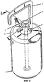
фиг.1 представляет собой вид в аксонометрии устройства в соответствии с данным изобретением, расположенного в его предпочтительной или перевернутой, конфигурации «использования»;figure 1 is a perspective view of a device in accordance with this invention, located in its preferred or inverted configuration "use";
фиг.2 представляет собой другой вид в аксонометрии, подобный виду, показанному на фиг.1;FIG. 2 is another perspective view similar to that shown in FIG. 1;
фиг.3(a) представляет собой вид в разрезе первого варианта выполнения предлагаемого устройства по линии 3-3, показанной на фиг.1;figure 3 (a) is a sectional view of a first embodiment of the proposed device along the line 3-3 shown in figure 1;
фиг.3(b) представляет собой вид, подобный виду, показанному на фиг.3(а), второго варианта выполнения предлагаемого устройства;figure 3 (b) is a view similar to the view shown in figure 3 (a), a second embodiment of the proposed device;
фиг.4 представляет собой вид в разрезе средства, используемого в соответствии с данным изобретением для предотвращения или, по существу, устранения возможности противотока герметизирующего состава;4 is a sectional view of the means used in accordance with this invention to prevent or essentially eliminate the possibility of countercurrent sealing compound;
фиг.5 (слева направо) показывает соответствующие покомпонентные виды в аксонометрии снизу и сверху узла, показанного на фиг.4;Fig. 5 (from left to right) shows corresponding exploded perspective views from the bottom and top of the assembly of Fig. 4;
фиг.6 представляет собой покомпонентный вид предлагаемого устройства, иллюстрирующий принцип его работы.6 is an exploded view of the proposed device, illustrating the principle of its operation.
ОПИСАНИЕ ПРЕДПОЧТИТЕЛЬНЫХ ВАРИАНТОВ ВЫПОЛНЕНИЯDESCRIPTION OF PREFERRED EMBODIMENTS
В данном описании приведены варианты выполнения устройства в соответствии с данным изобретением, которое служит в качестве ремонтного комплекта или набора ремонтных инструментов, который можно иметь при себе или некоторым образом разместить в автомобиле в состоянии, готовом для использования в случае повреждения, например прокола, шины этого автомобиля. Данное устройство содержит, в качестве основных компонентов, герметичный контейнер 1, предназначенный для размещения подходящего герметизирующего состава и выполненный с возможностью, при использовании, присоединения (с возможностью отсоединения) к источнику воздуха или газа под давлением, извлекающий блок, выполненный с возможностью соединения с контейнером 1, и средство, обеспечивающее при необходимости регулирование выпуска герметизирующего состава из контейнера в поврежденную шину. Предпочтительно, но не обязательно, контейнер 1 выполнен так, что при использовании его располагают в перевернутом положении, например, как показано на фиг.1 и 2, при этом извлекающий блок служит в качестве средства подставки или стойки.In this description, embodiments of the device in accordance with this invention, which serves as a repair kit or a set of repair tools that can be carried with you or in some way placed in a car in a condition ready for use in the event of damage, such as a puncture, this tire a car. This device contains, as the main components, a sealed
Обратимся теперь к чертежам, на которых показан контейнер 1, предпочтительно выполненный из подходящего материала в форме бутыли, например из пластика (предпочтительно из пластмассы, пригодной к переработке для вторичного использования). Контейнер 1 имеет, по существу, цилиндрическую горловину 2, которая в предпочтительном варианте выполнена с наружным резьбовым участком 3. В частном предпочтительном варианте выполнения контейнер 1 дополнительно содержит, в виде его неотъемлемой части, клапан 4, который предпочтительно выполнен в виде клапана «обычного» типа (одностороннего действия), предусматривающего простое присоединение контейнера 1 к источнику подходящего газа или текучей среды под давлением, независимо от того, выполнен он в виде баллона или сходного контейнера, удерживающего воздух/газ или другую текучую среду при повышенном давлении, или как вариант в виде компрессора или подобного устройства (не показан), который может являться частью всего автомобиля или храниться отдельно для использования при необходимости.Turning now to the drawings, in which
Что касается фактического содержимого контейнера 1, то оно не являются частью данного изобретения. Возможно использование любого подходящего состава с известными герметизирующими свойствами. Однако в частном предпочтительном варианте выполнения герметизирующий состав не должен быть выполнен на основе латекса.As for the actual contents of the
Данное устройство дополнительно содержит извлекающий блок, который в качестве одного компонента содержит извлекающий узел, обозначенный в целом номером 10 позиции, по существу, с цилиндрическим поперечным сечением, размер и общая форма которого, по существу, дополняют размер и форму горловины 2 контейнера 1. Извлекающий узел 10 также предпочтительно выполнен из подходящей пластмассы, например, формованием. Однако следует понимать, что ни материал конструкции, ни способ выполнения как контейнера 1, так и узла 10 не являются частью данного изобретения.This device further comprises an extraction unit, which as one component comprises an extraction unit, indicated generally by the
В показанном предпочтительном варианте выполнения данное устройство также содержит средство, которое облегчает его транспортировку и/или хранение. Подобное средство может содержать ручку 7, которая предпочтительно крепится к извлекающему узлу 10 с возможностью отсоединения. Ручка 7 имеет по существу L-образную форму и может иметь на конце одного своего плеча или вблизи него отверстие, предназначенное при использовании для пропускания через него профилированного болта или сходного выступающего средства 8, выполненного на наружной периферии извлекающего узла 10. Ручка 7 дополнительно содержит участок 9 уменьшенной толщины вблизи указанного отверстия, который служит в качестве шарнира, обеспечивающего складывание ручки 7 для облегчения хранения всего устройства, когда оно не используется.In the shown preferred embodiment, this device also contains means that facilitate its transportation and / or storage. Such a tool may comprise a
Извлекающий блок как первый основной компонент представляет собой извлекающий узел 10, который содержит первую по существу цилиндрическую часть 11 с внутренней резьбой 12, которая имеет размер и форму, дополняющие размер и форму резьбы, выполненной снаружи горловины 2 контейнера, для обеспечения соединения с резьбовым участком 3 горловины 2 контейнера 1. Предпочтительно горловина 2 и первая часть 11 извлекающего узла 10 имеют по существу одинаковую длину.The extraction unit as the first main component is an
Извлекающий узел 10 у свободного конца, противоположного первой части 11, содержит вторую по существу цилиндрическую часть 13, которая при использовании обеспечивает опорное основание или подставку, обеспечивающую поддержку всего устройства на определенной поверхности в конфигурации или расположении, показанном на фиг.1, 2, 3(a), 3(b) и 6. Поперек извлекающего узла 10 около соединения частей 11 и 13 проходит поперечная пластина или стенка 14, которая содержит по существу полую трубку 15, расположенную по существу по ее центру и проходящую от нее вверх в направлении первой части 11. Предпочтительно трубка 15 имеет длину, достаточную для выхода за пределы самого верхнего конца первой части 11 узла 10 и, соответственно, прохода в основной корпус контейнера 1. Пластина или стенка 14 дополнительно содержит множество окружных разнесенных буртиков 16 и 17 или подобных им, причем буртик 16 служит для облегчения расположения узла 10 относительно резьбовой горловины 2 контейнера 1, как показано, например, на фиг.3(а) и 3(b).The extracting
В показанных предпочтительных вариантах выполнения трубка 15 проходит вниз в нижнюю полую часть извлекающего узла 10, переходя в выпускную трубку 18, которая рассмотренным ниже способом обеспечивает прохождение герметизирующего состава из контейнера 1 к герметизируемому изделию, при необходимости. Предпочтительно выпускная трубка 18 у наружного свободного конца, который, как показано, проходит наружу из узла 10, содержит средство, обеспечивающее присоединение к отрезку шланга или системе труб (не показана), посредством которого все устройство (контейнер 1 и связанный с ним извлекающий блок) может быть присоединено, при необходимости, к герметизируемому изделию. Предпочтительно свободный конец выпускной трубки 18 выполнен с участком 19 большего или увеличенного наружного диаметра, с одним или более буртиков или схожих элементов 20, которые выполнены на его наружной поверхности или проходящих по меньшей мере частично вокруг нее, чтобы способствовать удержанию на нем с возможностью отсоединения отрезка шланга или трубки. В другом варианте выполнения свободный конец выпускной трубки 18 может иметь резьбу, предусматривающую съемное присоединение к отрезку шланга дополняющей конфигурации или трубке, в свою очередь присоединенной к герметизируемому изделию.In the preferred embodiments shown, the
Для того чтобы обеспечить регулируемое распределение герметизирующего состава из контейнера 1, а также свести к минимуму, если не ликвидировать вообще, возможность противотока герметизирующего состава, предлагаемое устройство содержит узел погруженной трубки, который обозначен в общем номером 30 позиции и предназначен для размещения в контейнере 1 и проточного сообщения с трубкой 15 извлекающего узла 10 извлекающего блока. В частном предпочтительном варианте выполнения, см. например, фиг.3(а), узел погруженной трубки имеет форму отрезка трубки 31, у которого при использовании один конец расположен поверх трубки 15 и который проходит по существу на всю высоту собственно контейнера 1, причем указанный конец трубки 31 содержит периферический фланец 32 с таким размером, как показано на чертежах, что когда трубка 31 установлена на место, то его наружная периферия входит в контакт с поверхностью пластины 14 и ее периферическим буртиком 17. В другом варианте выполнения, показанном на фиг.3(b), узел 30 погруженной трубки выполнен в виде двух отдельных смежных отрезков 31(a) и 31(b) трубки, причем трубка 31(a) расположена поверх трубки 15 извлекающего узла 10, а второй отрезок 31(b) трубки расположен, посредством плотной посадки, поверх свободного конца указанного первого отрезка 31(a) трубки. С этой целью, и как показано на фиг.3(b), около свободного конца первого отрезка 31(a) трубки выполнен участок 33 с уменьшенным наружным диаметром. В каждом случае у свободного конца трубки 31, как показано на фиг.3(а), или отрезка 31(a), как показано на фиг.3(b), выполнен уплотнительный узел, обозначенный в общем номером 40 позиции. В другом варианте выполнения, не показанном на чертежах, уплотнительный узел 40 может быть расположен на свободном конце трубки 15, поверх нее, без какой либо промежуточной трубки.In order to ensure the controlled distribution of the sealing composition from the
Что касается узла 40, то он имеет форму колпачка 41, который выполнен с возможностью съемного соединения с периферическим фланцем 34, выполненным на свободном конце трубки 31, 31(b), или прикрепления к нему. В частном предпочтительном варианте выполнения колпачок 41 имеет форму по существу цилиндрического элемента, по существу, с плоским основанием 42 и периферической юбкой 43, проходящей от него вниз. Основание 42 содержит расположенную по существу по его центру направленную вниз втулку 44, которая имеет по существу цилиндрическую форму, но со смежными или граничащими участками с различным наружным диаметром, между которыми выполнен выступ 45. Основание 42 дополнительно содержит одно или более отверстий 46, предпочтительно расположенных симметрично относительно проходящей вниз втулки 44. Узел 40 предпочтительно содержит кольцевое уплотнение или подобный уплотнительный элемент из любого подходящего материала, например резины, которое приспособлено, при использовании, для размещения в узле 40 с «посадкой» на выступ 45, как показано на фиг.4.As for the
Далее приведено подробное объяснение принципа работы всего устройства со ссылкой на фиг.6.The following is a detailed explanation of the principle of operation of the entire device with reference to Fig.6.
При необходимости повторной герметизации проколотой шины контейнер 1 (с герметизирующим составом, находящимся в нем) сначала присоединяют к источнику воздуха/газа/текучей среды под давлением посредством клапана 4 и соответствующей трубки. Дополнительную трубку затем присоединяют к выпускной трубке 18 извлекающего узла 10, а от нее к собственно шине. Когда воздух или газ под давлением вводят в контейнер 1, как схематически показано сплошными стрелками на фиг.6, внутри контейнера 1 повышается внутреннее давление, которое воздействует на кольцевое уплотнение 47, заставляя его соскальзывать с втулки 44, а именно с выступа 45 и вдоль трубки 31, 31(a), обеспечивая распределение герметизирующего состава, как схематически показано светлыми стрелками, из контейнера 1 через отверстия 46, выполненные в основании 42 колпачка 41, в погруженную трубку 31, 31(a) по ее длине, а затем через трубку 15 в выпускную трубку 18 извлекающего узла 10 для последующего введения в собственно шину.If it is necessary to re-seal the punctured tire, the container 1 (with the sealing compound contained therein) is first connected to the air / gas / fluid source under pressure by means of
На практике уплотнительный механизм может быть помещен на конец погруженной трубки 31 или, в другом варианте, может быть расположен непосредственно в первой части 11 извлекающего узла. Это означает, что данный контейнер может быть опорожнен даже в перевернутом положении.In practice, the sealing mechanism may be placed at the end of the immersed
Предлагаемая заявителем конструкция обеспечивает использование контейнера 1 в перевернутом или опрокинутом положении, а также его опорожнение. Кроме того, работа предлагаемой конструкции по существу устраняет опасность противотока герметизирующего состава в источник воздуха или газа под давлением. Если подача герметизирующего состава прерывается до опорожнения контейнера, то действие погруженной трубки, имеющей уплотнительное средство, препятствует противотоку в случае, когда ослабевает давление внутри контейнера, так как кольцевое уплотнение будет перемещаться обратно к положению на выступе 45 втулки 44, предотвращая дальнейшее распределение герметизирующего состава через отверстия 46 колпачка 41.The design proposed by the applicant ensures the use of the
В дополнительном предпочтительном варианте выполнения, не показанном на чертежах, извлекающий блок может быть устройством известного типа, как показано, например, в патенте США № 4308766, которое содержит как средство удаления сердечника клапана шины (так и, соответственно, средство возврата), так и средство введения жидкого герметизирующего состава в надувную шину.In a further preferred embodiment, not shown in the drawings, the extraction unit may be a device of a known type, as shown, for example, in US Pat. No. 4,308,766, which contains both means for removing the valve core of the tire (and therefore return means), and means for introducing a liquid sealant into the inflatable tire.
В заключение, следует понимать, что вышеприведенное описание относится просто к предпочтительным вариантам выполнения данного изобретения и что возможно внесение в него изменений и модификаций без отклонения от сущности и объема правовой охраны данного изобретения, который определяется из последующей формулы изобретения.In conclusion, it should be understood that the above description refers simply to the preferred embodiments of the present invention and that it is possible to make changes and modifications without deviating from the essence and scope of legal protection of the present invention, which is determined from the following claims.
Claims (30)
Applications Claiming Priority (2)
| Application Number | Priority Date | Filing Date | Title |
|---|---|---|---|
| AU2005905041 | 2005-09-13 | ||
| AU2005905041A AU2005905041A0 (en) | 2005-09-13 | Improvements in sealing apparatus |
Publications (2)
| Publication Number | Publication Date |
|---|---|
| RU2008111881A RU2008111881A (en) | 2009-10-20 |
| RU2385229C2 true RU2385229C2 (en) | 2010-03-27 |
Family
ID=37864576
Family Applications (1)
| Application Number | Title | Priority Date | Filing Date |
|---|---|---|---|
| RU2008111881A RU2385229C2 (en) | 2005-09-13 | 2006-09-13 | Perfected sealing device |
Country Status (16)
| Country | Link |
|---|---|
| US (1) | US8205645B2 (en) |
| EP (1) | EP1931509B1 (en) |
| JP (1) | JP4991726B2 (en) |
| KR (1) | KR101290481B1 (en) |
| CN (1) | CN101291799B (en) |
| BR (1) | BRPI0617262B1 (en) |
| CA (1) | CA2622768C (en) |
| EG (1) | EG25349A (en) |
| IL (1) | IL190106A (en) |
| MX (1) | MX2008003465A (en) |
| MY (1) | MY151777A (en) |
| NO (1) | NO342109B1 (en) |
| NZ (1) | NZ567236A (en) |
| RU (1) | RU2385229C2 (en) |
| WO (1) | WO2007030896A1 (en) |
| ZA (1) | ZA200802330B (en) |
Cited By (1)
| Publication number | Priority date | Publication date | Assignee | Title |
|---|---|---|---|---|
| RU2729796C2 (en) * | 2016-02-17 | 2020-08-12 | Тридел Рисерч Питиуай Элтэдэ | Improved device for sealing and pumping of damaged inflatable products, such as punctured tires |
Families Citing this family (30)
| Publication number | Priority date | Publication date | Assignee | Title |
|---|---|---|---|---|
| JP4871106B2 (en) | 2006-06-20 | 2012-02-08 | 株式会社ブリヂストン | Sealing / pump-up device |
| DE102007026776A1 (en) * | 2007-06-09 | 2008-12-11 | Continental Aktiengesellschaft | Reifenabdichtvorrichtung |
| WO2009003967A2 (en) * | 2007-06-29 | 2009-01-08 | Premium Seal Entwicklungs- Und Marketing Gmbh & Co. Kg | Device for sealing tires |
| DE102007030462A1 (en) * | 2007-06-29 | 2009-01-08 | Premium Vertriebs Gmbh | Pneumatic tire sealing device for vehicle, has connecting pipe provided between sealant receptacle and propellant cylinder to feed propellant to sealant, and attachment provided on receptacle to feed sealant and propellant into tire |
| DE102007053241A1 (en) * | 2007-11-06 | 2009-05-07 | Continental Aktiengesellschaft | Device with a valve unit for sealing and inflating inflatable objects |
| DE102008015022B3 (en) * | 2008-03-19 | 2009-11-05 | Continental Aktiengesellschaft | Roadside Assistance System |
| WO2010078626A1 (en) * | 2009-01-07 | 2010-07-15 | Trydel Research Pty. Ltd. | Apparatus for repairing and inflating of damaged inflatable articles |
| EP2497629B1 (en) * | 2009-11-04 | 2016-12-14 | Sumitomo Rubber Industries, Ltd. | Puncture repair kit |
| US20120091380A1 (en) * | 2010-05-07 | 2012-04-19 | Daas Ip Management, Llc | Combination Valve Assembly |
| WO2012102078A1 (en) * | 2011-01-28 | 2012-08-02 | 住友ゴム工業株式会社 | Flat tire repair kit |
| TWI482908B (en) * | 2011-03-07 | 2015-05-01 | Wen San Chou | Air compressor for vehicle |
| JP5568068B2 (en) * | 2011-09-20 | 2014-08-06 | 住友ゴム工業株式会社 | Punk repair kit |
| WO2013040880A1 (en) | 2011-09-21 | 2013-03-28 | 精联科技有限公司 | Vehicle tyre repair glue bottle |
| JP5476351B2 (en) * | 2011-09-28 | 2014-04-23 | 住友ゴム工業株式会社 | Cap unit for puncture repair |
| US8746293B2 (en) * | 2011-10-12 | 2014-06-10 | Wen San Chou | Device for sealing and inflating inflatable object |
| JP5568101B2 (en) * | 2012-02-03 | 2014-08-06 | 住友ゴム工業株式会社 | Integrated puncture repair kit |
| US9492976B2 (en) * | 2012-10-17 | 2016-11-15 | Active Tools International (Hk) Ltd. | Sealant bottle for tire repair of vehicle |
| US9050866B2 (en) * | 2013-03-20 | 2015-06-09 | Active Tools International (Hk) Ltd. | Sealant bottle for tire repair of gas pressure type |
| US10914425B2 (en) | 2013-05-02 | 2021-02-09 | Ysn Imports, Inc. | Combination valve assembly with actuatable overfill relief |
| US9193229B2 (en) * | 2013-12-03 | 2015-11-24 | Top Alliance Technology Limited | Tire repair device |
| JP5725231B1 (en) | 2014-04-16 | 2015-05-27 | 横浜ゴム株式会社 | Puncture repair liquid container |
| JP5682722B1 (en) * | 2014-04-16 | 2015-03-11 | 横浜ゴム株式会社 | Puncture repair liquid container |
| US10611105B2 (en) | 2017-02-10 | 2020-04-07 | Illinois Tool Works Inc. | Aerosol dispensing cap for automated installation |
| JP1585573S (en) * | 2017-03-14 | 2017-09-11 | ||
| JP1585572S (en) * | 2017-03-14 | 2017-09-11 | ||
| USD823365S1 (en) * | 2017-03-31 | 2018-07-17 | Wong Wai Kan | Tire repair kit |
| JP7271981B2 (en) * | 2019-02-06 | 2023-05-12 | 横浜ゴム株式会社 | puncture repair kit |
| USD915885S1 (en) | 2019-03-20 | 2021-04-13 | Illinois Tool Works Inc. | Aerosol dispensing cap |
| US11242190B2 (en) | 2019-03-20 | 2022-02-08 | Illinois Tool Works Inc. | Aerosol dispensing cap for automated installation |
| DE102021205682A1 (en) | 2021-06-04 | 2022-12-08 | Continental Reifen Deutschland Gmbh | Sealant device for sealing a vehicle tire, breakdown assistance set with such a sealant device and a method for producing such a sealant device |
Family Cites Families (14)
| Publication number | Priority date | Publication date | Assignee | Title |
|---|---|---|---|---|
| US3908871A (en) * | 1974-10-15 | 1975-09-30 | Double Check Ind Inc | Keg closure and coupler assembly |
| US4308766A (en) * | 1980-03-31 | 1982-01-05 | Myers Jr James E | Liquid tire sealant injection tool |
| JPH03112314U (en) * | 1990-03-01 | 1991-11-18 | ||
| DE19549592C5 (en) * | 1995-07-11 | 2006-12-14 | Sumitomo Rubber Industries Ltd., Kobe | Device for sealing and inflating tires in the event of breakdowns |
| DE19652546B4 (en) * | 1996-12-17 | 2012-11-22 | Sumitomo Rubber Industries Ltd. | Means for sealing tires during breakdowns, devices for sealing and inflating tires and tires with integrated sealing means |
| US6176285B1 (en) * | 1996-12-17 | 2001-01-23 | Sumitomo Rubber Industries, Ltd. | Preparation for the sealing of tires with punctures, apparatus for the sealing and pumping up of tires and tires with an integrated sealing preparation |
| DE19846451C5 (en) * | 1998-10-08 | 2018-08-23 | Sumitomo Rubber Industries Ltd. | Device for sealing inflatable objects, in particular tires |
| JP2000309254A (en) * | 1999-04-26 | 2000-11-07 | Sumitomo Rubber Ind Ltd | Tire sealing and pumping-up device |
| DE10015166A1 (en) * | 2000-03-27 | 2001-10-04 | Dunlop Gmbh | Puncture repair device for tires comprises canister of sealant on to which adapter is screwed which has gas inlet and outlet which is applied to tire, ends of inlet and outlet nearest canister being fitted with valve opened by gas pressure |
| CN100425435C (en) | 2001-11-15 | 2008-10-15 | 共荣国际有限公司 | Device for sealing and inflating an inflatable object |
| JP4133945B2 (en) * | 2004-06-28 | 2008-08-13 | 住友ゴム工業株式会社 | Tire puncture sealant supply and extraction device |
| DE102004042911A1 (en) * | 2004-09-02 | 2006-03-09 | Michael Stehle | Device for dispensing air and / or tire sealant |
| DE202005005291U1 (en) * | 2005-04-04 | 2005-09-08 | Wang, Min-Hsieng | Tire repair compound injector comprises a compound container with internal pump and suction tube connecting with tube for connection to a tire |
| ATE448074T1 (en) * | 2006-02-07 | 2009-11-15 | Doukas Ag | DEVICE FOR DISPENSING TIRE SEALANT FROM A CONTAINER |
-
2006
- 2006-09-13 CA CA 2622768 patent/CA2622768C/en active Active
- 2006-09-13 CN CN2006800390951A patent/CN101291799B/en active Active
- 2006-09-13 MY MYPI20080659A patent/MY151777A/en unknown
- 2006-09-13 KR KR1020087008383A patent/KR101290481B1/en active IP Right Grant
- 2006-09-13 WO PCT/AU2006/001365 patent/WO2007030896A1/en active Application Filing
- 2006-09-13 US US12/066,635 patent/US8205645B2/en active Active
- 2006-09-13 JP JP2008530277A patent/JP4991726B2/en active Active
- 2006-09-13 RU RU2008111881A patent/RU2385229C2/en active
- 2006-09-13 EP EP06774993.7A patent/EP1931509B1/en active Active
- 2006-09-13 BR BRPI0617262-8A patent/BRPI0617262B1/en active IP Right Grant
- 2006-09-13 MX MX2008003465A patent/MX2008003465A/en active IP Right Grant
- 2006-09-13 NZ NZ567236A patent/NZ567236A/en unknown
-
2008
- 2008-03-11 IL IL190106A patent/IL190106A/en active IP Right Grant
- 2008-03-12 ZA ZA200802330A patent/ZA200802330B/en unknown
- 2008-04-10 NO NO20081762A patent/NO342109B1/en unknown
-
2009
- 2009-12-24 EG EG2009121909A patent/EG25349A/en active
Cited By (1)
| Publication number | Priority date | Publication date | Assignee | Title |
|---|---|---|---|---|
| RU2729796C2 (en) * | 2016-02-17 | 2020-08-12 | Тридел Рисерч Питиуай Элтэдэ | Improved device for sealing and pumping of damaged inflatable products, such as punctured tires |
Also Published As
| Publication number | Publication date |
|---|---|
| US20080264540A1 (en) | 2008-10-30 |
| BRPI0617262A2 (en) | 2011-07-19 |
| NO20081762L (en) | 2008-06-11 |
| JP2009507682A (en) | 2009-02-26 |
| EP1931509B1 (en) | 2017-07-19 |
| KR101290481B1 (en) | 2013-07-26 |
| CN101291799A (en) | 2008-10-22 |
| EG25349A (en) | 2011-12-15 |
| RU2008111881A (en) | 2009-10-20 |
| MY151777A (en) | 2014-07-14 |
| US8205645B2 (en) | 2012-06-26 |
| MX2008003465A (en) | 2008-10-03 |
| NO342109B1 (en) | 2018-03-26 |
| NZ567236A (en) | 2010-04-30 |
| WO2007030896A1 (en) | 2007-03-22 |
| CA2622768C (en) | 2014-01-21 |
| IL190106A (en) | 2012-02-29 |
| EP1931509A1 (en) | 2008-06-18 |
| CN101291799B (en) | 2012-01-11 |
| JP4991726B2 (en) | 2012-08-01 |
| KR20080056196A (en) | 2008-06-20 |
| EP1931509A4 (en) | 2012-11-07 |
| ZA200802330B (en) | 2009-06-24 |
| IL190106A0 (en) | 2008-08-07 |
| BRPI0617262B1 (en) | 2018-03-27 |
| CA2622768A1 (en) | 2007-03-22 |
Similar Documents
| Publication | Publication Date | Title |
|---|---|---|
| RU2385229C2 (en) | Perfected sealing device | |
| US6766834B1 (en) | Sealing apparatus | |
| AU782129B2 (en) | Sealing device | |
| US6874656B2 (en) | Vented closure | |
| JP5416117B2 (en) | Fluid distribution method and apparatus | |
| US7178564B2 (en) | Supplying/removing apparatus of puncture sealant of tire | |
| EP1598288B1 (en) | Method of fitting liquid container bag body, and liquid container | |
| WO2009052576A1 (en) | Apparatus for sealing inflatable articles | |
| EP0825955B1 (en) | Refillable closed container system | |
| US6009685A (en) | Method and device for isolated filling of a container | |
| AU2006291959A1 (en) | Improvements in sealing apparatus | |
| CZ2013647A3 (en) | Composite bottle for transportation and storage of especially LPG and apparatus for making the same |