RU2379100C2 - Reactor and method of performing endothermic or exothermic catalytic reactions - Google Patents
Reactor and method of performing endothermic or exothermic catalytic reactions Download PDFInfo
- Publication number
- RU2379100C2 RU2379100C2 RU2007119438/12A RU2007119438A RU2379100C2 RU 2379100 C2 RU2379100 C2 RU 2379100C2 RU 2007119438/12 A RU2007119438/12 A RU 2007119438/12A RU 2007119438 A RU2007119438 A RU 2007119438A RU 2379100 C2 RU2379100 C2 RU 2379100C2
- Authority
- RU
- Russia
- Prior art keywords
- heat transfer
- reactor
- pipes
- transfer pipes
- catalyst
- Prior art date
Links
Images

Classifications
-
- B—PERFORMING OPERATIONS; TRANSPORTING
- B01—PHYSICAL OR CHEMICAL PROCESSES OR APPARATUS IN GENERAL
- B01J—CHEMICAL OR PHYSICAL PROCESSES, e.g. CATALYSIS OR COLLOID CHEMISTRY; THEIR RELEVANT APPARATUS
- B01J8/00—Chemical or physical processes in general, conducted in the presence of fluids and solid particles; Apparatus for such processes
- B01J8/02—Chemical or physical processes in general, conducted in the presence of fluids and solid particles; Apparatus for such processes with stationary particles, e.g. in fixed beds
-
- C—CHEMISTRY; METALLURGY
- C01—INORGANIC CHEMISTRY
- C01B—NON-METALLIC ELEMENTS; COMPOUNDS THEREOF; METALLOIDS OR COMPOUNDS THEREOF NOT COVERED BY SUBCLASS C01C
- C01B3/00—Hydrogen; Gaseous mixtures containing hydrogen; Separation of hydrogen from mixtures containing it; Purification of hydrogen
- C01B3/02—Production of hydrogen or of gaseous mixtures containing a substantial proportion of hydrogen
- C01B3/32—Production of hydrogen or of gaseous mixtures containing a substantial proportion of hydrogen by reaction of gaseous or liquid organic compounds with gasifying agents, e.g. water, carbon dioxide, air
- C01B3/34—Production of hydrogen or of gaseous mixtures containing a substantial proportion of hydrogen by reaction of gaseous or liquid organic compounds with gasifying agents, e.g. water, carbon dioxide, air by reaction of hydrocarbons with gasifying agents
- C01B3/38—Production of hydrogen or of gaseous mixtures containing a substantial proportion of hydrogen by reaction of gaseous or liquid organic compounds with gasifying agents, e.g. water, carbon dioxide, air by reaction of hydrocarbons with gasifying agents using catalysts
- C01B3/384—Production of hydrogen or of gaseous mixtures containing a substantial proportion of hydrogen by reaction of gaseous or liquid organic compounds with gasifying agents, e.g. water, carbon dioxide, air by reaction of hydrocarbons with gasifying agents using catalysts the catalyst being continuously externally heated
-
- B—PERFORMING OPERATIONS; TRANSPORTING
- B01—PHYSICAL OR CHEMICAL PROCESSES OR APPARATUS IN GENERAL
- B01J—CHEMICAL OR PHYSICAL PROCESSES, e.g. CATALYSIS OR COLLOID CHEMISTRY; THEIR RELEVANT APPARATUS
- B01J8/00—Chemical or physical processes in general, conducted in the presence of fluids and solid particles; Apparatus for such processes
- B01J8/008—Details of the reactor or of the particulate material; Processes to increase or to retard the rate of reaction
-
- B—PERFORMING OPERATIONS; TRANSPORTING
- B01—PHYSICAL OR CHEMICAL PROCESSES OR APPARATUS IN GENERAL
- B01J—CHEMICAL OR PHYSICAL PROCESSES, e.g. CATALYSIS OR COLLOID CHEMISTRY; THEIR RELEVANT APPARATUS
- B01J8/00—Chemical or physical processes in general, conducted in the presence of fluids and solid particles; Apparatus for such processes
- B01J8/02—Chemical or physical processes in general, conducted in the presence of fluids and solid particles; Apparatus for such processes with stationary particles, e.g. in fixed beds
- B01J8/0207—Chemical or physical processes in general, conducted in the presence of fluids and solid particles; Apparatus for such processes with stationary particles, e.g. in fixed beds the fluid flow within the bed being predominantly horizontal
- B01J8/0221—Chemical or physical processes in general, conducted in the presence of fluids and solid particles; Apparatus for such processes with stationary particles, e.g. in fixed beds the fluid flow within the bed being predominantly horizontal in a cylindrical shaped bed
-
- B—PERFORMING OPERATIONS; TRANSPORTING
- B01—PHYSICAL OR CHEMICAL PROCESSES OR APPARATUS IN GENERAL
- B01J—CHEMICAL OR PHYSICAL PROCESSES, e.g. CATALYSIS OR COLLOID CHEMISTRY; THEIR RELEVANT APPARATUS
- B01J8/00—Chemical or physical processes in general, conducted in the presence of fluids and solid particles; Apparatus for such processes
- B01J8/02—Chemical or physical processes in general, conducted in the presence of fluids and solid particles; Apparatus for such processes with stationary particles, e.g. in fixed beds
- B01J8/0242—Chemical or physical processes in general, conducted in the presence of fluids and solid particles; Apparatus for such processes with stationary particles, e.g. in fixed beds the fluid flow within the bed being predominantly vertical
- B01J8/025—Chemical or physical processes in general, conducted in the presence of fluids and solid particles; Apparatus for such processes with stationary particles, e.g. in fixed beds the fluid flow within the bed being predominantly vertical in a cylindrical shaped bed
-
- B—PERFORMING OPERATIONS; TRANSPORTING
- B01—PHYSICAL OR CHEMICAL PROCESSES OR APPARATUS IN GENERAL
- B01J—CHEMICAL OR PHYSICAL PROCESSES, e.g. CATALYSIS OR COLLOID CHEMISTRY; THEIR RELEVANT APPARATUS
- B01J8/00—Chemical or physical processes in general, conducted in the presence of fluids and solid particles; Apparatus for such processes
- B01J8/02—Chemical or physical processes in general, conducted in the presence of fluids and solid particles; Apparatus for such processes with stationary particles, e.g. in fixed beds
- B01J8/0285—Heating or cooling the reactor
-
- C—CHEMISTRY; METALLURGY
- C01—INORGANIC CHEMISTRY
- C01B—NON-METALLIC ELEMENTS; COMPOUNDS THEREOF; METALLOIDS OR COMPOUNDS THEREOF NOT COVERED BY SUBCLASS C01C
- C01B3/00—Hydrogen; Gaseous mixtures containing hydrogen; Separation of hydrogen from mixtures containing it; Purification of hydrogen
- C01B3/02—Production of hydrogen or of gaseous mixtures containing a substantial proportion of hydrogen
- C01B3/32—Production of hydrogen or of gaseous mixtures containing a substantial proportion of hydrogen by reaction of gaseous or liquid organic compounds with gasifying agents, e.g. water, carbon dioxide, air
- C01B3/34—Production of hydrogen or of gaseous mixtures containing a substantial proportion of hydrogen by reaction of gaseous or liquid organic compounds with gasifying agents, e.g. water, carbon dioxide, air by reaction of hydrocarbons with gasifying agents
- C01B3/38—Production of hydrogen or of gaseous mixtures containing a substantial proportion of hydrogen by reaction of gaseous or liquid organic compounds with gasifying agents, e.g. water, carbon dioxide, air by reaction of hydrocarbons with gasifying agents using catalysts
-
- B—PERFORMING OPERATIONS; TRANSPORTING
- B01—PHYSICAL OR CHEMICAL PROCESSES OR APPARATUS IN GENERAL
- B01J—CHEMICAL OR PHYSICAL PROCESSES, e.g. CATALYSIS OR COLLOID CHEMISTRY; THEIR RELEVANT APPARATUS
- B01J2208/00—Processes carried out in the presence of solid particles; Reactors therefor
- B01J2208/00008—Controlling the process
- B01J2208/00017—Controlling the temperature
- B01J2208/00106—Controlling the temperature by indirect heat exchange
- B01J2208/00115—Controlling the temperature by indirect heat exchange with heat exchange elements inside the bed of solid particles
- B01J2208/00132—Tubes
-
- B—PERFORMING OPERATIONS; TRANSPORTING
- B01—PHYSICAL OR CHEMICAL PROCESSES OR APPARATUS IN GENERAL
- B01J—CHEMICAL OR PHYSICAL PROCESSES, e.g. CATALYSIS OR COLLOID CHEMISTRY; THEIR RELEVANT APPARATUS
- B01J2208/00—Processes carried out in the presence of solid particles; Reactors therefor
- B01J2208/00008—Controlling the process
- B01J2208/00017—Controlling the temperature
- B01J2208/00106—Controlling the temperature by indirect heat exchange
- B01J2208/00168—Controlling the temperature by indirect heat exchange with heat exchange elements outside the bed of solid particles
- B01J2208/00212—Plates; Jackets; Cylinders
-
- B—PERFORMING OPERATIONS; TRANSPORTING
- B01—PHYSICAL OR CHEMICAL PROCESSES OR APPARATUS IN GENERAL
- B01J—CHEMICAL OR PHYSICAL PROCESSES, e.g. CATALYSIS OR COLLOID CHEMISTRY; THEIR RELEVANT APPARATUS
- B01J2219/00—Chemical, physical or physico-chemical processes in general; Their relevant apparatus
- B01J2219/02—Apparatus characterised by their chemically-resistant properties
- B01J2219/025—Apparatus characterised by their chemically-resistant properties characterised by the construction materials of the reactor vessel proper
- B01J2219/0277—Metal based
- B01J2219/0286—Steel
-
- C—CHEMISTRY; METALLURGY
- C01—INORGANIC CHEMISTRY
- C01B—NON-METALLIC ELEMENTS; COMPOUNDS THEREOF; METALLOIDS OR COMPOUNDS THEREOF NOT COVERED BY SUBCLASS C01C
- C01B2203/00—Integrated processes for the production of hydrogen or synthesis gas
- C01B2203/02—Processes for making hydrogen or synthesis gas
- C01B2203/0205—Processes for making hydrogen or synthesis gas containing a reforming step
- C01B2203/0227—Processes for making hydrogen or synthesis gas containing a reforming step containing a catalytic reforming step
- C01B2203/0233—Processes for making hydrogen or synthesis gas containing a reforming step containing a catalytic reforming step the reforming step being a steam reforming step
-
- C—CHEMISTRY; METALLURGY
- C01—INORGANIC CHEMISTRY
- C01B—NON-METALLIC ELEMENTS; COMPOUNDS THEREOF; METALLOIDS OR COMPOUNDS THEREOF NOT COVERED BY SUBCLASS C01C
- C01B2203/00—Integrated processes for the production of hydrogen or synthesis gas
- C01B2203/02—Processes for making hydrogen or synthesis gas
- C01B2203/0205—Processes for making hydrogen or synthesis gas containing a reforming step
- C01B2203/0227—Processes for making hydrogen or synthesis gas containing a reforming step containing a catalytic reforming step
- C01B2203/0244—Processes for making hydrogen or synthesis gas containing a reforming step containing a catalytic reforming step the reforming step being an autothermal reforming step, e.g. secondary reforming processes
-
- C—CHEMISTRY; METALLURGY
- C01—INORGANIC CHEMISTRY
- C01B—NON-METALLIC ELEMENTS; COMPOUNDS THEREOF; METALLOIDS OR COMPOUNDS THEREOF NOT COVERED BY SUBCLASS C01C
- C01B2203/00—Integrated processes for the production of hydrogen or synthesis gas
- C01B2203/08—Methods of heating or cooling
- C01B2203/0805—Methods of heating the process for making hydrogen or synthesis gas
- C01B2203/0838—Methods of heating the process for making hydrogen or synthesis gas by heat exchange with exothermic reactions, other than by combustion of fuel
- C01B2203/0844—Methods of heating the process for making hydrogen or synthesis gas by heat exchange with exothermic reactions, other than by combustion of fuel the non-combustive exothermic reaction being another reforming reaction as defined in groups C01B2203/02 - C01B2203/0294
-
- C—CHEMISTRY; METALLURGY
- C01—INORGANIC CHEMISTRY
- C01B—NON-METALLIC ELEMENTS; COMPOUNDS THEREOF; METALLOIDS OR COMPOUNDS THEREOF NOT COVERED BY SUBCLASS C01C
- C01B2203/00—Integrated processes for the production of hydrogen or synthesis gas
- C01B2203/14—Details of the flowsheet
- C01B2203/141—At least two reforming, decomposition or partial oxidation steps in parallel
-
- Y—GENERAL TAGGING OF NEW TECHNOLOGICAL DEVELOPMENTS; GENERAL TAGGING OF CROSS-SECTIONAL TECHNOLOGIES SPANNING OVER SEVERAL SECTIONS OF THE IPC; TECHNICAL SUBJECTS COVERED BY FORMER USPC CROSS-REFERENCE ART COLLECTIONS [XRACs] AND DIGESTS
- Y02—TECHNOLOGIES OR APPLICATIONS FOR MITIGATION OR ADAPTATION AGAINST CLIMATE CHANGE
- Y02P—CLIMATE CHANGE MITIGATION TECHNOLOGIES IN THE PRODUCTION OR PROCESSING OF GOODS
- Y02P20/00—Technologies relating to chemical industry
- Y02P20/50—Improvements relating to the production of bulk chemicals
- Y02P20/52—Improvements relating to the production of bulk chemicals using catalysts, e.g. selective catalysts
Abstract
Description
Область изобретенияField of Invention
Это изобретение относится к улучшенному теплообменному реактору и способу проведения эндотермических или экзотермических каталитических реакций. В частности, это изобретение относится к улучшенному теплообменному реактору и способу использования в паровом реформинге исходного углеводородного сырья для производства синтез-газа, содержащего водород и окись углерода.This invention relates to an improved heat exchange reactor and method for conducting endothermic or exothermic catalytic reactions. In particular, this invention relates to an improved heat exchange reactor and a method for using hydrocarbon feedstock for steam reforming to produce synthesis gas containing hydrogen and carbon monoxide.
Уровень техникиState of the art
Каталитические реакторы для проведения эндотермических или экзотермических реакций хорошо известны специалистам, причем конкретные примеры представляют собой реакторы для эндотермического парового реформинга углеводородов и реакторы для экзотермической реакции синтеза метанола. Эти реакции обычно проводят в трубах, загруженных подходящим твердым катализатором, через который пропускают при повышенном давлении технологический газовый поток, содержащий реагенты. Множество труб устанавливают вертикально или горизонтально в реакторе. Эти трубы идут параллельно главной оси каталитического реактора, в то время как внешняя теплообменная среда нагревает или охлаждает трубы. Твердый катализатор внутри труб обеспечивает слой катализатора, в котором протекают требуемые химические реакции. Катализатор может быть обеспечен в виде твердых частиц или в виде покрытой структуры, например, в виде тонкого слоя, фиксированного на внутренней стенке труб в реакторе парового реформинга.Catalytic reactors for carrying out endothermic or exothermic reactions are well known in the art, with specific examples being reactors for endothermic steam reforming of hydrocarbons and reactors for an exothermic reaction of methanol synthesis. These reactions are usually carried out in tubes loaded with a suitable solid catalyst, through which a process gas stream containing reactants is passed under elevated pressure. Many pipes are installed vertically or horizontally in the reactor. These pipes run parallel to the main axis of the catalytic reactor, while the external heat transfer medium heats or cools the pipes. The solid catalyst inside the tubes provides a catalyst bed in which the required chemical reactions proceed. The catalyst may be provided in the form of solid particles or in the form of a coated structure, for example, in the form of a thin layer fixed on the inner wall of the pipes in the steam reforming reactor.
В другой конфигурации реактора, содержащей множество труб, частицы твердого катализатора могут быть расположены вне указанных труб, в дальнейшем упоминаемых также как трубы теплопередачи, в то время как теплообменная среда проходит внутри. Твердый катализатор вне труб теплопередачи обеспечивает слой катализатора, в котором протекают требуемые химические реакции.In another configuration of a reactor containing a plurality of pipes, solid catalyst particles can be located outside said pipes, hereinafter also referred to as heat transfer pipes, while the heat exchange medium passes inside. A solid catalyst outside the heat transfer pipes provides a catalyst bed in which the required chemical reactions proceed.
Конкретный тип трубы теплопередачи, используемой в теплообменных реакторах, представляет собой так называемую двойную трубу. Двойная труба представляет собой в основном конструкцию из двух, по существу, концентрических труб. Пространство между стенками труб образует кольцевую полость, через которую теплообменная среда может течь так, чтобы регулирование температуры достигалось косвенным теплообменом между технологическим потоком, проходящим через слой катализатора, и указанной теплообменной средой. В конструкции, содержащей множество двойных труб, твердый катализатор в слое предпочтительно расположен как снаружи, так и внутри двойных труб.The particular type of heat transfer pipe used in heat exchange reactors is the so-called double pipe. The double pipe is basically a construction of two essentially concentric pipes. The space between the pipe walls forms an annular cavity through which the heat transfer medium can flow so that temperature control is achieved by indirect heat exchange between the process stream passing through the catalyst bed and said heat transfer medium. In a structure comprising a plurality of double pipes, the solid catalyst in the bed is preferably located both outside and inside the double pipes.
Еще один тип труб теплопередачи в теплообменных реакторах представляет собой расположение двух, по существу, концентрических труб, но где внутренняя труба закрыта с одного или обоих концов, либо просто представляет собой твердый удлиненный элемент, такой как металлический брусок или стержень. Пространство между стенками трубы образует кольцевую полость для прохождения теплообменной среды. В расположении, содержащем множество такого типа труб теплопередачи, твердый слой катализатора расположен только снаружи указанных труб.Another type of heat transfer pipes in heat exchange reactors is the arrangement of two essentially concentric pipes, but where the inner pipe is closed at one or both ends, or simply represents a solid elongated element, such as a metal bar or rod. The space between the walls of the pipe forms an annular cavity for the passage of the heat transfer medium. In an arrangement containing a plurality of this type of heat transfer pipes, a solid catalyst layer is located only outside of said pipes.
В этом описании термины "каталитический реактор", "теплообменный реактор" и "реактор" используют попеременно. Под "слоем катализатора" понимают объем твердого катализатора, формирующий указанный слой, который расположен снаружи труб теплопередачи и, возможно, в случае двойных труб, также внутри указанных труб. Термины "трубы теплопередачи" и "трубы" используют попеременно в этом описании, и покрытие любой трубы находится в контакте с катализатором, а также теплообменной средой для проведения каталитических реакций.In this description, the terms “catalytic reactor”, “heat exchange reactor” and “reactor” are used interchangeably. By "catalyst bed" is meant the volume of solid catalyst forming the specified layer, which is located outside the heat transfer pipes and, possibly, in the case of double pipes, also inside these pipes. The terms "heat transfer pipes" and "pipes" are used interchangeably in this description, and the coating of any pipe is in contact with the catalyst, as well as the heat exchange medium for carrying out catalytic reactions.
Процесс и реактор, в котором катализатор находится в не прямом контакте с теплообменной средой, известны из заявки ЕР-А-0271299. Этот источник раскрывает реактор и процесс, который объединяет паровой реформинг и автотермический реформинг. Зона парового реформинга, расположенная в нижней части реактора, содержит ряд труб с катализатором, расположенным внутри, в то время как в верхней части реактора расположен катализатор автотермического реформинга снаружи труб парового реформинга. Заявка ЕР-А-1106570 раскрывает процесс парового реформинга в параллельно соединенных трубчатых установках реформинга (реакторах), содержащих ряд труб парового реформинга, который нагревают не прямым теплообменом. Катализатор расположен в одном реакторе снаружи труб реформинга и внутри труб парового реформинга в другом реакторе.A process and a reactor in which the catalyst is not in direct contact with a heat transfer medium are known from EP-A-0271299. This source discloses a reactor and a process that combines steam reforming and autothermal reforming. The steam reforming zone located in the lower part of the reactor contains a series of pipes with a catalyst located inside, while in the upper part of the reactor there is an autothermal reforming catalyst outside the steam reforming pipes. Application EP-A-1106570 discloses a steam reforming process in parallel-connected tubular reforming units (reactors) containing a series of steam reforming pipes that are heated by non-direct heat exchange. The catalyst is located in one reactor outside the reforming pipes and inside the steam reforming pipes in another reactor.
В конфигурациях реактора, содержащего частицы твердого катализатора, расположенные в виде слоя снаружи множества труб теплопередачи, например в трубах парового реформинга, расположение таких труб теплопередачи имеет критическое значение, так как было бы желательно достигать равномерного распределения температуры через радиальное направление реактора. Другими словами, было бы желательно, чтобы в любом данном поперечном сечении вдоль высоты реактора температура слоя катализатора в радиальном направлении оставалась настолько постоянной, насколько возможно.In reactor configurations containing solid catalyst particles arranged in a layer outside a plurality of heat transfer pipes, for example in steam reforming pipes, the location of such heat transfer pipes is critical since it would be desirable to achieve uniform temperature distribution across the radial direction of the reactor. In other words, it would be desirable for the temperature of the catalyst bed in the radial direction to remain as constant as possible in any given cross section along the height of the reactor.
При заданной длине или высоте реактора не трудно получать почти одинаковые отношения площади катализатора (область поперечного сечения реактора, заполненная катализатором) к площади теплопередачи (внешней поверхности труб теплопередачи) и, таким образом, равномерное распределение температуры во внутренней части поперечного сечения слоя катализатора, то есть по направлению к центру реактора. Это отношение может поддерживаться постоянным, если, например, расположение труб сохраняется постоянным для трубы теплопередачи одинакового диаметра. Под расположением трубы понимают расстояние от центра до центра соседних труб. Даже изменение от, например, треугольного расположения в центре слоя к прямоугольному расположению около периферии слоя может быть получено без испытания слишком больших вариаций в отношении площади катализатора к площади теплопередачи. Однако на периферии нагреваемого или охлаждаемого слоя катализатора окружающая внешняя стенка реактора, образующая периферию реактора, не нагревает и не охлаждает слой катализатора. На внешней периферии указанного слоя катализатора, то есть в областях около внешней стенки реактора, может быть невозможным получать отношение площади катализатора к площади теплопередачи, аналогичное отношению, получаемому по направлению к центру реактора. Это в особенности имеет место, когда некоторое минимальное расстояние требуется между наиболее удаленными трубами теплопередачи и внешней стенкой реактора так, чтобы частицы катализатора были способны окружать всю внешнюю поверхность указанных труб теплопередачи. Если внешняя стенка реактора находится очень близко к внешней стенке наиболее удаленных труб теплопередачи или в прямом контакте с ними, твердые частицы катализатора могут быть не способны занимать место между стенкой и указанными трубами.For a given length or height of the reactor, it is not difficult to obtain almost the same ratio of the area of the catalyst (the cross-sectional area of the reactor filled with the catalyst) to the heat transfer area (outer surface of the heat transfer pipes) and, thus, a uniform temperature distribution in the inner part of the cross section of the catalyst layer, i.e. towards the center of the reactor. This ratio can be kept constant if, for example, the pipe arrangement is kept constant for a heat transfer pipe of the same diameter. Under the location of the pipe understand the distance from the center to the center of adjacent pipes. Even a change from, for example, a triangular arrangement in the center of the layer to a rectangular arrangement near the periphery of the layer can be obtained without testing too large variations in the ratio of the catalyst area to the heat transfer area. However, at the periphery of the heated or cooled catalyst bed, the surrounding external wall of the reactor, forming the periphery of the reactor, does not heat and cool the catalyst bed. At the outer periphery of said catalyst bed, that is, in areas near the outer wall of the reactor, it may not be possible to obtain a ratio of the area of the catalyst to the heat transfer area similar to that obtained towards the center of the reactor. This is especially the case when a certain minimum distance is required between the outermost heat transfer pipes and the outer wall of the reactor so that the catalyst particles are able to surround the entire outer surface of said heat transfer pipes. If the outer wall of the reactor is very close to the outer wall of the outermost heat transfer pipes or in direct contact with them, solid catalyst particles may not be able to occupy a space between the wall and these pipes.
Следовательно, могут быть созданы мертвые углы или не содержащие катализатора области. Пустое пространство, сформированное этими не содержащими катализатора областями, приводит к нежелательному образованию газовых каналов с сопутствующими нежелательными эффектами в отношении неравномерного потока, неравномерного распределения температуры в слое катализатора, а также не превращенного или хуже прореагировавшего технологического газа.Therefore, dead corners or catalyst-free areas can be created. The empty space formed by these catalyst-free regions leads to undesirable gas channel formation with attendant undesirable effects with respect to uneven flow, uneven temperature distribution in the catalyst bed, and unreformed or worse reacted process gas.
Краткое содержание изобретенияSummary of invention
Мы теперь разработали реактор, который простым способом неожиданно преодолевает указанные выше проблемы. В соответствии с изобретением мы обеспечиваем теплообменный реактор для проведения эндотермических или экзотермических реакций, содержащий кожух, образующий внешнюю стенку реактора, множество труб теплопередачи, расположенных внутри указанного кожуха для подачи или удаления тепла в слоях катализатора, расположенных, по меньшей мере, снаружи указанных труб теплопередачи, и встроенные элементы, которые представляют собой удлиненные элементы, продолжающиеся параллельно относительно труб теплопередачи и расположены во внешней периферии указанного слоя катализатора, при этом указанные встроенные элементы являются периферийными трубами теплопередачи, через которые проходит теплообменная среда, и указанная теплообменная среда представляет собой газ, проходящий в противотоке к потоку технологического газа, проходящему через указанный слой катализатора.We have now developed a reactor that unexpectedly overcomes the above problems in a simple way. In accordance with the invention, we provide a heat exchange reactor for carrying out endothermic or exothermic reactions, comprising a casing forming the outer wall of the reactor, a plurality of heat transfer pipes located inside said casing for supplying or removing heat in catalyst beds located at least outside said heat transfer pipes , and built-in elements, which are elongated elements that extend parallel to the heat transfer pipes and are located in the outer periphery and said catalyst bed, wherein said built-in elements are peripheral heat transfer tubes through which the heat transfer medium passes, and said heat transfer medium is a gas flowing in countercurrent to a process gas stream passing through said catalyst bed.
Таким образом, изобретение относится к обеспечению встроенных элементов во внешней периферии слоев катализатора в теплообменных реакторах, где твердые частицы катализатора расположены снаружи труб теплопередачи. Под "внешней периферией слоев катализатора" понимают область, заключенную между внешней стенкой наиболее удаленной трубы теплопередачи и внешней стенкой реактора. Под термином "катализатор, расположенный, по меньшей мере, снаружи указанных труб теплопередачи" понимают, что катализатор в реакторе расположен снаружи труб, но он также может быть расположен как в качестве катализатора вне, так и внутри указанных труб, когда они представляют собой двойные трубы. Соответственно реактор, в котором катализатор расположен только внутри труб, находится вне объема этого изобретения. Под "встроенными элементами" понимают элементы, которые помещены около или в прямом контакте с внешней стенкой реактора и которые служат, чтобы создавать отношение площади катализатора к площади теплопередачи во внешней периферии слоя катализатора, аналогичное тому, что достигают в оставшемся поперечном сечении слоя. Обеспечение встроенных элементов, которые продлевают элементы, проходящие параллельно по отношению к трубам теплопередачи расположения реактора, снижает количество катализатора в областях возле внешней стенки реактора. Следовательно, встроенные элементы эффективно понижают площадь катализатора и, в то же время, могут добавлять площадь теплопередачи для удаления тепла или охлаждения. Подходящие встроенные элементы могут быть удлиненными элементами подходящей толщины и формы, такими как стержни, например металлические стержни, которые оказывают небольшое воздействие в отношении теплообмена, но все же служат для создания отношения площади катализатора к площади теплопередачи во внешней периферии слоя катализатора, аналогичное тому, что достигают в остающемся поперечном сечении слоя. Предпочтительно встроенные элементы представляют собой трубы теплопередачи, так как они дополнительно позволяют теплообменной среде проходить через них. Эти трубы в дальнейшем также называют как "периферийные трубы теплопередачи".Thus, the invention relates to the provision of embedded elements in the outer periphery of the catalyst beds in heat exchange reactors, where solid catalyst particles are located outside the heat transfer pipes. By "outer periphery of the catalyst beds" is meant a region enclosed between the outer wall of the outermost heat transfer pipe and the outer wall of the reactor. By the term “catalyst located at least outside of said heat transfer pipes” is meant that the catalyst in the reactor is located outside of the pipes, but it can also be located both outside and inside these pipes as a catalyst when they are double pipes . Accordingly, a reactor in which the catalyst is located only inside the pipes is outside the scope of this invention. By “integrated elements” is meant elements that are placed near or in direct contact with the outer wall of the reactor and which serve to create a ratio of the catalyst area to the heat transfer area in the outer periphery of the catalyst bed, similar to that achieved in the remaining cross section of the bed. Providing built-in elements that extend elements running parallel to the heat transfer pipes of the reactor arrangement reduces the amount of catalyst in the areas near the outer wall of the reactor. Therefore, the built-in elements effectively reduce the area of the catalyst and, at the same time, can add heat transfer area to remove heat or cooling. Suitable embedded elements may be elongated elements of suitable thickness and shape, such as rods, for example metal rods, which have little effect on heat transfer, but still serve to create a ratio of the area of the catalyst to the area of heat transfer in the outer periphery of the catalyst layer, similar to that reach in the remaining cross section of the layer. Preferably, the built-in elements are heat transfer pipes, since they additionally allow the heat exchange medium to pass through them. These pipes are hereinafter also referred to as “peripheral heat transfer pipes”.
Соответственно с помощью изобретения достигают более равномерного распределения температуры по всему слою в реакторе и в особенности около внешних стенок реактора. Поскольку температура по направлению к внешней стенке реактора может быть сохранена на почти том же самом уровне, как и в центре реактора, достигают более ровных технологических условий, и может быть получена более высокая конверсия технологического газа, например, при высоко эндотермической реакции парового реформинга.Accordingly, by means of the invention, a more uniform temperature distribution is achieved over the entire layer in the reactor, and in particular near the outer walls of the reactor. Since the temperature towards the outer wall of the reactor can be kept at almost the same level as in the center of the reactor, more even technological conditions are achieved, and a higher conversion of the process gas can be obtained, for example, with a highly endothermic steam reforming reaction.
В предпочтительном варианте осуществления изобретения периферические трубы теплопередачи имеют площадь поперечного сечения, которая меньше, чем обычные трубы теплопередачи в остальной части слоя катализатора. Поперечное сечение периферических труб теплопередачи имеет такую форму, чтобы должным образом соответствовать области между наиболее удаленными трубами теплопередачи в расположении нагревающей трубы, то есть размещением труб переноса тепла внутри реактора, и внешней стенкой реактора. Под термином "чтобы соответствовать должным образом" понимают, что частицы катализатора способны заполнять пространство между наиболее удаленными трубами теплопередачи и периферическими трубами теплопередачи так, чтобы свести к минимуму образование газовых каналов.In a preferred embodiment, the peripheral heat transfer tubes have a cross-sectional area that is smaller than conventional heat transfer tubes in the rest of the catalyst bed. The cross-section of the peripheral heat transfer pipes is shaped so as to properly correspond to the area between the outermost heat transfer pipes in the location of the heating pipe, that is, the placement of the heat transfer pipes inside the reactor, and the outer wall of the reactor. By the term “to fit properly” is meant that the catalyst particles are capable of filling the space between the outermost heat transfer tubes and the peripheral heat transfer tubes so as to minimize the formation of gas channels.
Периферические трубы теплопередачи предпочтительно расположены в прямом контакте с внешней стенкой реактора. Периферические трубы теплопередачи могут быть простыми трубами, имеющими одну стенку, и могут быть сформированы так, чтобы иметь, по существу, полукруглое или треугольное поперечное сечение. Могут быть предусмотрены другие типы труб, например двойные трубы.The peripheral heat transfer tubes are preferably located in direct contact with the outer wall of the reactor. The peripheral heat transfer pipes may be simple pipes having one wall, and may be formed to have a substantially semicircular or triangular cross section. Other types of pipes may be provided, for example double pipes.
Аналогично, если встроенные элементы представляют собой стержни, например металлические стержни, их поперечное сечение формируют так, что они соответствуют должным образом области между наиболее удаленными трубами теплопередачи в расположении нагревающей трубы, то есть в расположение между трубами переноса тепла внутри реактора, и внешней стенкой реактора. Указанные стержни также могут быть сформированы так, чтобы иметь, по существу, полукруглое или треугольное поперечное сечение. Другие формы могут быть очевидными для специалистов. В одном варианте осуществления изобретения твердые частицы катализатора, формирующие слой катализатора, обеспечены снаружи труб теплопередачи, расположенных внутри кожуха теплообменного реактор, а не внутри указанных труб теплопередачи. То есть катализатор расположен только вне труб теплопередачи. В другом варианте осуществления изобретения трубы теплопередачи, расположенные внутри кожуха теплообменного реактора, представляют собой двойные трубы; твердые частицы катализатора, формирующие слой катализатора, расположены как вне, так и внутри указанных двойных труб.Similarly, if the built-in elements are rods, for example metal rods, their cross section is formed so that they correspond properly to the area between the farthest heat transfer pipes in the location of the heating pipe, that is, to the location between the heat transfer pipes inside the reactor and the outer wall of the reactor . These rods may also be formed so as to have a substantially semicircular or triangular cross section. Other forms may be apparent to those skilled in the art. In one embodiment of the invention, solid catalyst particles forming a catalyst layer are provided outside the heat transfer pipes located inside the shell of the heat exchange reactor, and not inside said heat transfer pipes. That is, the catalyst is located only outside the heat transfer pipes. In another embodiment, the heat transfer pipes located inside the shell of the heat exchange reactor are double pipes; solid catalyst particles forming the catalyst layer are located both outside and inside said double pipes.
Область снаружи периферийных труб теплопередачи заполнена твердыми частицами катализатора, которые формируют часть слоя катализатора снаружи труб теплопередачи.The area outside the peripheral heat transfer pipes is filled with solid catalyst particles that form part of the catalyst layer outside the heat transfer pipes.
Краткое описание чертежейBrief Description of the Drawings
Изобретение иллюстрировано сопровождающими чертежами.The invention is illustrated in the accompanying drawings.
Фиг.1 - вид в сечении цилиндрического теплообменного реактора радиуса R, содержащегося внутри кожуха или оболочки под давлением, (не показаны).Figure 1 is a view in section of a cylindrical heat exchange reactor of radius R contained inside the casing or shell under pressure (not shown).
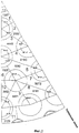
Фиг.2 - вид в сечении сегмента 30° теплообменного реактора, где показан только наружный диаметр внешней трубы из двойных труб.Figure 2 is a view in cross section of a 30 ° segment of a heat exchange reactor, which shows only the outer diameter of the outer pipe from double pipes.
Подробное описание предпочтительных вариантов осуществления изобретенияDETAILED DESCRIPTION OF PREFERRED EMBODIMENTS
На Фиг.1 периферия реактора образована внешней стенкой 1, которая представляет собой металлическую стенку, например, из нержавеющей стали. Внутренняя часть реактора содержит множество труб теплопередачи 2, которые в принципе могут иметь любую форму, но предпочтительно являются цилиндрическими, то есть с круглым поперечным сечением. Пространство между трубами теплопередачи 2 содержит частицы катализатора, формирующие слой катализатора 3. На этом чертеже, где указанные трубы теплопередачи 2 представляют собой двойные трубы, их внутренние трубы заполнены твердыми частицами катализатора 3′. Трубы теплопередачи 2 расположены так, чтобы обеспечивать равномерное распределение тепла и тем самым равномерную температуру по всему поперечному сечению реактора. Множество встроенных элементов, здесь периферийных труб теплопередачи 4, обеспечивающих дополнительную площадь теплообмена и снижающих количество катализатора около внешней стенки реактора 1, помещают вблизи указанной стенки 1 или в непосредственном контакте с ней, и они позволяют прохождение теплообменной среды 5 в противотоке с технологическим газом 6. Технологический газ 6, например газовая смесь, содержащая метан в качестве главного компонента, проходит через катализатор в направлении, поперечном к плоскости листа бумаги, и его охлаждают или нагревают косвенно теплообменной средой 5, проходящей в противотоке к технологическому газу 6 через кольцевое пространство, созданное между стенками труб теплопередачи 2.1, the periphery of the reactor is formed by an outer wall 1, which is a metal wall, for example, stainless steel. The inside of the reactor comprises a plurality of
Периферийные трубы теплопередачи 4 могут иметь любую форму, но предпочтительно представляют собой простые трубы с, по существу, полукруглой или, по существу, треугольной формой так, чтобы их более плоская область имела возможность соответствовать кривизне внешней стенки реактора 1. Указанные периферийные трубы теплопередачи 4 могут быть подогнаны к внешней стенке реактора 1 подходящими средствами закрепления, позволяющими разное тепловое расширение. Поперечное сечение периферийных труб теплопередачи 4 имеет большую ось d1 и малую ось d2, где указанная большая ось d1 образует гладкую область, которая способна подходить к кривизне внешней стенки реактора 1. Предпочтительно периферийные трубы теплопередачи 4 находятся в прямом контакте с внешней стенкой 1. Минимальное радиальное расстояние d обеспечено между внешней стенкой реактора 1 и наиболее удаленной стенкой наиболее удаленных труб теплопередачи 2 так, что твердые частицы катализатора 3 могут окружать всю внешнюю поверхность указанных труб теплопередачи 2.The peripheral
Обычно длина периферийных труб теплопередачи 4 и труб теплопередачи 2 приблизительно соответствует длине реактора, причем длина периферийных труб находится в интервале от 6 до 14 м. Толщина периферийных труб находится обычно в интервале 3-8 мм, в то время как трубы теплопередачи, здесь представленные двойными трубами, обычно имеют толщину внутренней стенки 2-6 мм и толщину внешней стенки 3-8 мм. Кольцевое пространство для прохождения теплообменной среды 5 в двойных трубах составляет не более около от 4 до 12 мм.Typically, the length of the peripheral
Ссылаясь теперь на Фиг.2, показанное расположение двойных труб представляет собой сегмент 30°, который может быть зеркально отражен на сегмент 60°. Эта секция 60° повторяется с образованием расположения трубы в полных 360°. Область снаружи труб, содержащая катализатор, может быть разделена на подобласти, ограниченные линиями, проведенными от центра двойной трубы до центра двойной трубы. Все такие области, содержащие катализатор, получают тепло от трех внешних труб, причем каждая труба, вносящая вклад в поверхность теплопередачи, которая соответствует 60° периметра трубы, таким образом, помогая полной поверхности теплопередачи, равной половине окружности внешней трубы (180°). Существуют одиннадцать участков разного размера между двойными трубами, которые образуют области, с номерами 1-11. Участки, обозначенные 1, 2, 6 и 10, показаны только наполовину и должны быть зеркально отражены (зеркальная линия представляет собой свободную сторону), чтобы обеспечить полную форму и размер этого конкретного участка.Referring now to FIG. 2, the arrangement of the double tubes shown is a 30 ° segment that can be mirrored to a 60 ° segment. This 60 ° section is repeated to form a full 360 ° pipe layout. The area outside the pipes containing the catalyst can be divided into subregions limited by lines drawn from the center of the double pipe to the center of the double pipe. All such regions containing the catalyst receive heat from three external pipes, with each pipe contributing to a heat transfer surface that corresponds to 60 ° of the perimeter of the pipe, thus helping to achieve a full heat transfer surface equal to half the circumference of the external pipe (180 °). There are eleven sections of different sizes between the double pipes that form the areas, numbered 1-11. The sections indicated by 1, 2, 6 and 10 are only shown halfway and should be mirrored (the mirror line represents the free side) to ensure the full shape and size of this particular section.
Трубы теплопередачи предпочтительно расположены в треугольной конфигурации, где минимальное расстояние от центра двойной трубы до центра двойной трубы составляет около 143 мм. Это приводит к расстоянию около 29 мм между внешними трубами из соседних двойных труб, что дает достаточное пространство для заполнения промежутка частицами катализатора.The heat transfer pipes are preferably arranged in a triangular configuration where the minimum distance from the center of the double pipe to the center of the double pipe is about 143 mm. This leads to a distance of about 29 mm between the outer pipes from the adjacent double pipes, which gives sufficient space to fill the gap with catalyst particles.
Были рассчитаны площади катализатора различных участков. Участок 1 с самой маленькой площадью 3774 мм2 (2×1887 мм2) наилучшим образом снабжается теплом, в то время как участок 10, имеющий самую большую площадь 5304 мм2 (2×2652 мм2), имеет самую слабую подачу тепла. Для этих двух участков, указанных выше, отношения площади катализатора к поверхности нагрева, определенные площадью катализатора, разделенной на внешний периметр внешних труб, составляют 21,0 мм2/мм и 29,5 мм2/мм соответственно. В ходе работы реактора, однако, будет некоторое смешивание переноса тепла газа и горизонтального теплопереноса поперек границ пронумерованных областей, которое будет стремиться к понижению влияние различия в площади катализатора на поверхность нагрева для различных участков.The catalyst areas of various sites were calculated. Section 1 with the smallest area of 3774 mm 2 (2 × 1887 mm 2 ) is best supplied with heat, while
Площадь катализатора снаружи труб была разделена на пять "колец катализатора" вдоль диаметра реактора, которые были ограничены линиями, проведенными между центрами двойных труб, лежащих на тот же самом или около того же самого диаметра. Результаты для наилучшего расположения труб приведены в таблице ниже.The area of the catalyst outside the tubes was divided into five “catalyst rings” along the diameter of the reactor, which were limited by lines drawn between the centers of the double tubes lying on the same or near the same diameter. The results for the best pipe arrangement are shown in the table below.
В пятом цикле величины, отмеченные значком *, включают поверхность теплопередачи от периферийных труб теплопередачи, имеющих треугольное поперечное сечение. Была подсчитана только площадь в контакте с катализатором.In the fifth cycle, the values indicated by the * symbol include the heat transfer surface from the peripheral heat transfer pipes having a triangular cross section. Only the area in contact with the catalyst was calculated.
Было обнаружено, что изменение площади катализатора по отношению к поверхности нагрева является удовлетворительно низким. Внутреннее кольцо (№1) является наиболее обеспечиваемым теплом, но составляет только 3,7% общей площади катализатора. Чтобы компенсировать потери тепла от внешних стенок реактора, поверхность теплопередачи во внешнем кольце (№5) превышает среднюю поверхность теплопередачи. Без периферийных труб теплопередачи общая площадь катализатора в кольце катализатора становится 171178 мм2, в то время как общий периметр поверхности нагрева в кольце составляет 4668 мм. Получено высокое значение отношения площади катализатора к поверхности нагрева: 36,7 мм.It has been found that the change in catalyst area with respect to the heating surface is satisfactorily low. The inner ring (No. 1) is the most provided heat, but only 3.7% of the total catalyst area. To compensate for heat loss from the outer walls of the reactor, the heat transfer surface in the outer ring (No. 5) exceeds the average heat transfer surface. Without peripheral heat transfer pipes, the total area of the catalyst in the catalyst ring becomes 171178 mm 2 , while the total perimeter of the heating surface in the ring is 4668 mm. A high value of the ratio of catalyst area to heating surface was obtained: 36.7 mm.
Расчеты вычислительной гидродинамики (CFD) подтверждают, что колебания температуры из слоя катализатора на внешней стороне труб лежат в пределах ±30°.Computational Fluid Dynamics (CFD) calculations confirm that temperature fluctuations from the catalyst layer on the outside of the tubes are within ± 30 °.
Изобретение в особенности полезно для парового реформинга углеводородного сырья, содержащего метан, посредством тепла, поставляемого от горячего газа, выходящего от реактора автотермического реформинга, помещенного ниже по ходу потока теплообменного реактора, и готового газа из процесса парового реформинга. Горячий газ, выходящий от реактора автотермического реформинга, имеющий температуру около 1050°С, объединяют с преобразованным технологическим газом в теплообменном реакторе по изобретению, который покидает слои катализатора в нижней части реактора при температуре около 880°С. Объединенный газ используют для косвенного нагревания слоев катализатора, расположенных вне труб теплопередачи расположения реактора, позволяя проходу указанного объединенного газа вверх через трубы теплопередачи, а также через периферийные трубы теплопередачи, которые установлены около или на внешней стенке реактора и параллельно трубам теплопередачи. Объединенный газ охлаждают от около 1000°С до около 650°С, причем при этой температуре он покидает реактор, и его удаляют в качестве обогащенного водородом потока синтез-газа для дальнейшей обработки.The invention is particularly useful for steam reforming a hydrocarbon feed containing methane by means of heat supplied from hot gas leaving the autothermal reforming reactor placed downstream of the heat exchange reactor and the finished gas from the steam reforming process. The hot gas leaving the autothermal reforming reactor having a temperature of about 1050 ° C. is combined with the converted process gas in the heat exchange reactor of the invention, which leaves the catalyst beds at the bottom of the reactor at a temperature of about 880 ° C. Combined gas is used to indirectly heat catalyst layers located outside the reactor’s heat transfer pipes, allowing said combined gas to pass upward through the heat transfer pipes, as well as through peripheral heat transfer pipes that are installed near or on the outer wall of the reactor and parallel to the heat transfer pipes. The combined gas is cooled from about 1000 ° C. to about 650 ° C., at which temperature it leaves the reactor and is removed as a hydrogen-rich synthesis gas stream for further processing.
Соответственно изобретение также охватывает процесс парового реформинга углеводородного сырья, содержащий: (а) формирование объединенного газа 5 в теплообменном реакторе в соответствии с п.1, путем объединения горячего газа, выходящего из автотермического устройства реформинга, с преобразованным технологическим газом 6, покидающим слои катализатора 3, 3′, расположенные, по меньшей мере, снаружи труб 2 теплопередачи реактора, (b) пропускание указанного объединенного газа 5 через кольцевое пространство указанных труб теплопередачи, которые являются предпочтительно двойными трубами, для косвенного обогрева указанных слоев катализатора 3, 3′, (с) удаление указанного объединенного газа 5 из теплообменного реактора в качестве потока обогащенного водородом синтез-газа, где теплообменный реактор содержит периферийные трубы теплопередачи 4, расположенные около внешней стенки реактора 1 или на ней так, что объединенный газ 5 из стадии (а) проходит через указанные периферийные трубы теплопередачи 4, установленные параллельно трубам теплопередачи 2.Accordingly, the invention also encompasses a steam reforming process for a hydrocarbon feedstock comprising: (a) forming the combined
Claims (7)
кожух, образующий внешнюю стенку реактора (1),
множество труб теплопередачи (2), расположенных внутри указанного кожуха, для подачи или удаления тепла в слоях катализатора (3, 3′), расположенных, по меньшей мере, снаружи (3) указанных труб теплопередачи (2), и встроенных элементов (4), которые являются удлиненными элементами, продолжающимися параллельно относительно труб теплопередачи, и расположены во внешней периферии указанного слоя катализатора (3), при этом указанные встроенные элементы являются периферийными трубами теплопередачи, через которые проходит теплообменная среда, и указанная теплообменная среда представляет собой газ, проходящий в направлении потока или в противотоке к потоку технологического газа, проходящему через указанный слой катализатора.1. A heat exchange reactor for conducting endothermic or exothermic reactions, containing
a casing forming the outer wall of the reactor (1),
a plurality of heat transfer pipes (2) located inside said casing for supplying or removing heat in catalyst layers (3, 3 ′) located at least outside (3) of said heat transfer pipes (2) and built-in elements (4) which are elongated elements extending in parallel with respect to the heat transfer pipes and are located in the outer periphery of said catalyst layer (3), wherein said built-in elements are peripheral heat transfer pipes through which the heat exchange medium passes, and The heat transfer medium is a gas flowing in the direction of flow or countercurrent to the process gas flow passing through the specified catalyst bed.
Applications Claiming Priority (2)
| Application Number | Priority Date | Filing Date | Title |
|---|---|---|---|
| DKPA200401635 | 2004-10-26 | ||
| DKPA200401635 | 2004-10-26 |
Publications (2)
| Publication Number | Publication Date |
|---|---|
| RU2007119438A RU2007119438A (en) | 2008-12-10 |
| RU2379100C2 true RU2379100C2 (en) | 2010-01-20 |
Family
ID=35645710
Family Applications (1)
| Application Number | Title | Priority Date | Filing Date |
|---|---|---|---|
| RU2007119438/12A RU2379100C2 (en) | 2004-10-26 | 2005-10-14 | Reactor and method of performing endothermic or exothermic catalytic reactions |
Country Status (13)
| Country | Link |
|---|---|
| US (1) | US7776285B2 (en) |
| EP (1) | EP1807190B1 (en) |
| JP (1) | JP2008517864A (en) |
| KR (1) | KR101252493B1 (en) |
| CN (1) | CN101060920B (en) |
| AR (1) | AR052118A1 (en) |
| CA (1) | CA2585028C (en) |
| ES (1) | ES2416331T3 (en) |
| MX (1) | MX2007004754A (en) |
| PL (1) | PL1807190T3 (en) |
| RU (1) | RU2379100C2 (en) |
| WO (1) | WO2006045457A1 (en) |
| ZA (1) | ZA200704300B (en) |
Cited By (1)
| Publication number | Priority date | Publication date | Assignee | Title |
|---|---|---|---|---|
| RU2451889C1 (en) * | 2011-04-14 | 2012-05-27 | Государственное образовательное учреждение высшего профессионального образования Казанский государственный технический университет им. А.Н. Туполева (КГТУ им. А.Н. Туполева) | Heat exchanger-reactor |
Families Citing this family (3)
| Publication number | Priority date | Publication date | Assignee | Title |
|---|---|---|---|---|
| US9683474B2 (en) * | 2013-08-30 | 2017-06-20 | Dürr Systems Inc. | Block channel geometries and arrangements of thermal oxidizers |
| FR3057654B1 (en) * | 2016-10-14 | 2019-06-28 | Axens | DEVICE FOR COOLING A SOLID HEATER FOR PRECISELY CONTROLLING THE TEMPERATURE, THE DEVICE THAT MAY BE ASSOCIATED WITH AN ENDOTHERMIC OR EXOTHERMIC PROCESS. |
| KR101982786B1 (en) * | 2017-12-01 | 2019-05-28 | 한국에너지기술연구원 | Fluidized bed reactor |
Family Cites Families (19)
| Publication number | Priority date | Publication date | Assignee | Title |
|---|---|---|---|---|
| ES183753Y (en) * | 1969-01-15 | 1974-08-16 | A REACTOR ELEMENT FOR THE CONSERVATION OF HYDROCARBONS. | |
| US3980440A (en) * | 1975-08-06 | 1976-09-14 | General Atomic Company | Catalyst tube assembly for steam-hydrocarbon reformer |
| JPS5839572B2 (en) * | 1979-04-03 | 1983-08-31 | 東洋エンジニアリング株式会社 | Reactor and its use |
| JPS61285389A (en) * | 1985-06-12 | 1986-12-16 | Toshiba Corp | Heat exchanger |
| DE3532413A1 (en) * | 1985-09-11 | 1987-03-12 | Uhde Gmbh | DEVICE FOR GENERATING SYNTHESIS GAS |
| GB8629497D0 (en) * | 1986-12-10 | 1987-01-21 | British Petroleum Co Plc | Apparatus |
| DK167242B1 (en) * | 1989-02-16 | 1993-09-27 | Topsoe Haldor As | APPARATUS AND PROCEDURE FOR EXOTHERMAL REACTIONS |
| DE4221837C1 (en) * | 1992-07-03 | 1993-08-19 | Uhde Gmbh, 4600 Dortmund, De | Shrouded catalytic reformer tube - with partially enclosed gas mixing zone, for prodn. of synthesis gas |
| US5520891A (en) * | 1994-02-01 | 1996-05-28 | Lee; Jing M. | Cross-flow, fixed-bed catalytic reactor |
| US5869011A (en) * | 1994-02-01 | 1999-02-09 | Lee; Jing Ming | Fixed-bed catalytic reactor |
| EP1294477A4 (en) * | 2000-06-29 | 2006-06-07 | H2Gen Innovations Inc | Improved system and integrated chemical reactor for hydrogen production through steam reforming of hydrocarbons |
| JP2002246055A (en) * | 2001-02-15 | 2002-08-30 | Daikin Ind Ltd | Device for removing carbon monoxide and fuel cell |
| US6855272B2 (en) * | 2001-07-18 | 2005-02-15 | Kellogg Brown & Root, Inc. | Low pressure drop reforming exchanger |
| JP4136497B2 (en) * | 2002-07-02 | 2008-08-20 | トヨタ自動車株式会社 | Steam mixing apparatus and fuel reforming apparatus |
| GB0301323D0 (en) * | 2003-01-21 | 2003-02-19 | Johnson Matthey Plc | Methanol synthesis |
| JP4033402B2 (en) * | 2004-04-27 | 2008-01-16 | 本田技研工業株式会社 | Heat exchanger |
| EP1600209A1 (en) * | 2004-05-29 | 2005-11-30 | Haldor Topsoe A/S | Heat exchange process and reactor |
| JP4477432B2 (en) * | 2004-06-29 | 2010-06-09 | 東洋エンジニアリング株式会社 | Reformer |
| US20070000172A1 (en) * | 2005-06-28 | 2007-01-04 | Michael Boe | Compact reforming reactor |
-
2005
- 2005-10-14 WO PCT/EP2005/011076 patent/WO2006045457A1/en active Application Filing
- 2005-10-14 RU RU2007119438/12A patent/RU2379100C2/en active
- 2005-10-14 PL PL05803822T patent/PL1807190T3/en unknown
- 2005-10-14 ES ES05803822T patent/ES2416331T3/en active Active
- 2005-10-14 CN CN2005800365476A patent/CN101060920B/en not_active Expired - Fee Related
- 2005-10-14 JP JP2007538295A patent/JP2008517864A/en active Pending
- 2005-10-14 EP EP05803822.5A patent/EP1807190B1/en active Active
- 2005-10-14 CA CA2585028A patent/CA2585028C/en not_active Expired - Fee Related
- 2005-10-14 MX MX2007004754A patent/MX2007004754A/en active IP Right Grant
- 2005-10-14 US US11/666,279 patent/US7776285B2/en active Active
- 2005-10-14 KR KR1020077011573A patent/KR101252493B1/en active IP Right Grant
- 2005-10-14 ZA ZA200704300A patent/ZA200704300B/en unknown
- 2005-10-26 AR ARP050104476A patent/AR052118A1/en not_active Application Discontinuation
Cited By (1)
| Publication number | Priority date | Publication date | Assignee | Title |
|---|---|---|---|---|
| RU2451889C1 (en) * | 2011-04-14 | 2012-05-27 | Государственное образовательное учреждение высшего профессионального образования Казанский государственный технический университет им. А.Н. Туполева (КГТУ им. А.Н. Туполева) | Heat exchanger-reactor |
Also Published As
| Publication number | Publication date |
|---|---|
| KR101252493B1 (en) | 2013-04-09 |
| EP1807190B1 (en) | 2013-05-15 |
| CA2585028C (en) | 2013-07-23 |
| EP1807190A1 (en) | 2007-07-18 |
| MX2007004754A (en) | 2007-05-11 |
| US20070255082A1 (en) | 2007-11-01 |
| KR20070084451A (en) | 2007-08-24 |
| CN101060920A (en) | 2007-10-24 |
| PL1807190T3 (en) | 2013-10-31 |
| WO2006045457A1 (en) | 2006-05-04 |
| US7776285B2 (en) | 2010-08-17 |
| RU2007119438A (en) | 2008-12-10 |
| JP2008517864A (en) | 2008-05-29 |
| ES2416331T3 (en) | 2013-07-31 |
| AR052118A1 (en) | 2007-03-07 |
| ZA200704300B (en) | 2008-09-25 |
| CA2585028A1 (en) | 2006-05-04 |
| CN101060920B (en) | 2010-12-08 |
Similar Documents
| Publication | Publication Date | Title |
|---|---|---|
| JP5667624B2 (en) | Multi-stage, multi-tube shell-and-tube reactor | |
| US5869011A (en) | Fixed-bed catalytic reactor | |
| CA2337824C (en) | Radial flow reactor | |
| CA2786448C (en) | Process and apparatus for reforming hydrocarbons | |
| KR101015876B1 (en) | Process and apparatus for the preparation of synthesis gas | |
| KR20100122898A (en) | Method and reactor for the preparation of methanol | |
| IE44718B1 (en) | Apparatus for the synthesis of ammonia | |
| KR101044621B1 (en) | Process and apparatus for the preparation of synthesis gas | |
| CN112204120B (en) | Method for carrying out catalytic gas phase reactions, tube bundle reactor and reactor system | |
| RU2379100C2 (en) | Reactor and method of performing endothermic or exothermic catalytic reactions | |
| KR101401355B1 (en) | A micro channel reactor for hydrocarbon reforming | |
| JPS5892456A (en) | Reactor | |
| JP2022506005A (en) | Steam reforming or dry reforming of hydrocarbons | |
| JP2008514536A (en) | Apparatus and method for selective oxidation of carbon monoxide | |
| JPH0363425B2 (en) | ||
| US9675950B2 (en) | Combination reactor system | |
| JP7441231B2 (en) | fixed bed equipment | |
| WO2023135938A1 (en) | Methanation reactor | |
| JP2024505162A (en) | Spiral flow catalytic heat exchange reactor | |
| CN116802452A (en) | Sealing device for heat exchange reactor | |
| JPH06172760A (en) | Gas reactor of multistep cooling type |