RU2376503C2 - Household appliance with fixation facilities - Google Patents
Household appliance with fixation facilities Download PDFInfo
- Publication number
- RU2376503C2 RU2376503C2 RU2006132915A RU2006132915A RU2376503C2 RU 2376503 C2 RU2376503 C2 RU 2376503C2 RU 2006132915 A RU2006132915 A RU 2006132915A RU 2006132915 A RU2006132915 A RU 2006132915A RU 2376503 C2 RU2376503 C2 RU 2376503C2
- Authority
- RU
- Russia
- Prior art keywords
- latch
- section
- locking element
- housing
- locking
- Prior art date
Links
- 235000011389 fruit/vegetable juice Nutrition 0.000 claims description 11
- 230000000284 resting effect Effects 0.000 claims description 2
- 238000006073 displacement reaction Methods 0.000 abstract 1
- 239000000126 substance Substances 0.000 abstract 1
- 239000011521 glass Substances 0.000 description 3
- 230000001066 destructive effect Effects 0.000 description 2
- 235000013305 food Nutrition 0.000 description 2
- 238000001816 cooling Methods 0.000 description 1
- 238000009434 installation Methods 0.000 description 1
- 238000004519 manufacturing process Methods 0.000 description 1
- 230000013011 mating Effects 0.000 description 1
- 238000012954 risk control Methods 0.000 description 1
- 238000000926 separation method Methods 0.000 description 1
- 239000007787 solid Substances 0.000 description 1
- 230000002269 spontaneous effect Effects 0.000 description 1
Images
Classifications
-
- F—MECHANICAL ENGINEERING; LIGHTING; HEATING; WEAPONS; BLASTING
- F16—ENGINEERING ELEMENTS AND UNITS; GENERAL MEASURES FOR PRODUCING AND MAINTAINING EFFECTIVE FUNCTIONING OF MACHINES OR INSTALLATIONS; THERMAL INSULATION IN GENERAL
- F16B—DEVICES FOR FASTENING OR SECURING CONSTRUCTIONAL ELEMENTS OR MACHINE PARTS TOGETHER, e.g. NAILS, BOLTS, CIRCLIPS, CLAMPS, CLIPS OR WEDGES; JOINTS OR JOINTING
- F16B5/00—Joining sheets or plates, e.g. panels, to one another or to strips or bars parallel to them
- F16B5/06—Joining sheets or plates, e.g. panels, to one another or to strips or bars parallel to them by means of clamps or clips
- F16B5/0607—Joining sheets or plates, e.g. panels, to one another or to strips or bars parallel to them by means of clamps or clips joining sheets or plates to each other
-
- Y—GENERAL TAGGING OF NEW TECHNOLOGICAL DEVELOPMENTS; GENERAL TAGGING OF CROSS-SECTIONAL TECHNOLOGIES SPANNING OVER SEVERAL SECTIONS OF THE IPC; TECHNICAL SUBJECTS COVERED BY FORMER USPC CROSS-REFERENCE ART COLLECTIONS [XRACs] AND DIGESTS
- Y10—TECHNICAL SUBJECTS COVERED BY FORMER USPC
- Y10T—TECHNICAL SUBJECTS COVERED BY FORMER US CLASSIFICATION
- Y10T292/00—Closure fasteners
- Y10T292/08—Bolts
- Y10T292/096—Sliding
- Y10T292/1014—Operating means
- Y10T292/1022—Rigid
- Y10T292/103—Spring-arm catch
Landscapes
- Engineering & Computer Science (AREA)
- General Engineering & Computer Science (AREA)
- Mechanical Engineering (AREA)
- Cookers (AREA)
- Food-Manufacturing Devices (AREA)
- Electric Stoves And Ranges (AREA)
- Connection Of Plates (AREA)
- Clamps And Clips (AREA)
- Hooks, Suction Cups, And Attachment By Adhesive Means (AREA)
- Casings For Electric Apparatus (AREA)
Abstract
Description
Область техникиTechnical field
Изобретение относится к бытовому прибору, имеющему, по меньшей мере, одну первую секцию корпуса с фиксатором, и, по меньшей мере, одну вторую секцию корпуса с контрфиксатором, каковые фиксатор и контрфиксатор предназначены для соединения секций корпуса и каковым придан запорный элемент, не позволяющий фиксатору при запертом положении запорного элемента отделиться от контрфиксатора.The invention relates to a household appliance having at least one first housing section with a latch, and at least one second housing section with a latch, which latch and latch are designed to connect the housing sections and which is given a locking element that does not allow the latch when the locked position of the locking element is separated from the counter-lock.
Уровень техникиState of the art
Из DE 10142508 А1 известно фиксирующее приспособление для закрепления первого тела, вставляемого во второе тело, причем первая стенка первого тела располагается в основном под прямым углом ко второй стенке второго тела, со стопорным зубцом, который расположен на внутренней стороне первой стенки, охваченной вторым телом, и который с помощью силы, оказываемой связанным с первым телом соединительным элементом, вдавливается в отверстие фиксатора.From DE 10142508 A1, a fixing device is known for securing the first body to be inserted into the second body, the first wall of the first body being located substantially at right angles to the second wall of the second body, with a locking tooth located on the inside of the first wall covered by the second body, and which, with the help of the force exerted by the connecting element connected to the first body, is pressed into the hole of the retainer.
Недостатком фиксирующего приспособления, известного из уровня техники, является трудоемкость монтажа и демонтажа фиксирующего приспособления.A disadvantage of the fixing device known from the prior art is the complexity of mounting and dismounting the fixing device.
Раскрытие изобретенияDisclosure of invention
Задача изобретения состоит в том, чтобы сделать фиксирующее приспособление данного типа более удобным для монтажа и демонтажа.The objective of the invention is to make the fixing device of this type more convenient for mounting and dismounting.
Согласно изобретению эта задача решена тем, что запорный элемент имеет первый конец, опирающийся на одну из секций корпуса, и второй конец, в запертом положении сцепляющийся с фиксатором. Это позволяет легко отсоединить запорный элемент и выполнить монтаж и демонтаж секций корпуса быстрее и проще.According to the invention, this problem is solved in that the locking element has a first end, resting on one of the sections of the housing, and a second end, in the locked position, engages with the latch. This makes it easy to detach the locking element and make mounting and dismounting of the housing sections quicker and easier.
В одном предпочтительном варианте реализации изобретения запорный элемент так крепится на секции корпуса, что его можно переместить из освобожденного в запертое положение предпочтительно посредством поворота. Это позволяет легко и просто поворачивать запорный элемент из освобожденного положения в запертое и обратно.In one preferred embodiment of the invention, the locking element is so attached to the housing section that it can be moved from the released to the locked position, preferably by rotation. This allows you to easily and simply rotate the locking element from the released position to the locked and vice versa.
Предпочтительно запорный элемент в освобожденном положении должен находиться в ненагруженном состоянии. Это значит, что запорный элемент в отклоненном, т.е. в запертом положении, прилегает к фиксатору с напряжением, оказывая на фиксатор дополнительное удерживающее усилие. Таким образом, запорный элемент в запертом положении предпочтительно упруго подпружинен к фиксатору.Preferably, the locking element in the released position should be in an unloaded state. This means that the locking element is rejected, i.e. in the locked position, is adjacent to the latch with tension, exerting an additional holding force on the latch. Thus, the locking element in the locked position is preferably resiliently spring loaded to the latch.
Второй конец запорного элемента в запертом положении может заходить в паз или сцепляться со стопорным зубцом фиксатора. При этом паз или стопорный зубец может располагаться на стороне фиксатора, обращенной от контрфиксатора. Стопорный зубец может быть выполнен, например, так, чтобы в виде крыши перекрывать верхний конец выполненного в виде пружинящего язычка запорного элемента. При этом верхний конец запорного элемента будет охвачен сверху и частично слева и справа. Выполненная в виде паза сопряженная деталь для запорного элемента может быть, например, канавкой в боковой стенке фиксатора, в которой зажимается верхний конец запорного элемента.The second end of the locking element in the locked position can go into the groove or engage with the locking tooth of the latch. In this case, the groove or retaining tooth may be located on the side of the latch facing away from the counter-latch. The locking tooth can be made, for example, so that in the form of a roof overlap the upper end of the locking element made in the form of a spring tongue. In this case, the upper end of the locking element will be covered from above and partially left and right. The groove-shaped mating part for the locking element can be, for example, a groove in the side wall of the latch in which the upper end of the locking element is clamped.
Запорный элемент предпочтительно выполняется в виде приформованного к секции корпуса пружинящего язычка, который может изгибаться из ненагруженного освобожденного положения, практически параллельного к фиксатору, в упруго напряженное запертое положение.The locking element is preferably made in the form of a spring tongue molded to the housing section, which can be bent from an unloaded released position practically parallel to the latch into an elastically strained locked position.
Фиксатор может быть приформован к первой секции корпуса в виде пружинящего стопорного крючка, который входит в контрфиксатор, выполненный в виде стопорной выемки или в виде стопорного зубца на второй секции корпуса.The latch can be molded to the first section of the housing in the form of a spring locking hook, which is included in the counter-lock, made in the form of a locking recess or in the form of a locking tooth on the second section of the housing.
Наоборот, фиксатор может быть приформован к первой секции корпуса в виде стопорного зубца или стопорной выемки, так чтобы с ними сцеплялся выполненный в виде пружинящего стопорного крючка контрфиксатор второй секции корпуса.On the contrary, the latch can be molded to the first section of the housing in the form of a locking tooth or locking recess, so that a counter-lock of the second section of the housing made in the form of a spring locking hook engages with them.
Для упрощенного запирания соединения фиксатор-контрфиксатор на той секции корпуса, на которой расположен запорный элемент, предусмотрено расположенное на стороне запорного элемента, дальней от фиксатора, первое отверстие в стенке, через которое можно ввести инструмент для поворота запорного элемента в запертое положение. Через это первое отверстие в стенке можно ввести инструмент, например шлицевую отвертку. При отклонении лезвия шлицевой отвертки запорный элемент поворачивается из своего освобожденного положения в направлении фиксатора, и второй конец запорного элемента вдавливается в стопорный зубец фиксатора, пока запорный элемент не будет зафиксирован в запертом положении. Так, с помощью простых инструментов можно освободить или запереть скрытое в корпусе бытового прибора соединение фиксатор-контрфиксатор. Дополнительное преимущество в случае приформовывания запорного элемента к первой секции корпуса состоит в том, что нет никаких дополнительных отдельных запорных элементов. Это упрощает монтаж, так как не требуется иметь под рукой никаких отдельных запорных инструментов. Вследствие снижения количества деталей удешевляется и весь процесс изготовления. Еще одно преимущество состоит в том, что запорные элементы соединены с первой секцией корпуса и их нельзя потерять.For simplified locking of the connection, the latch-counter-latch on the section of the housing on which the latching element is located provides for the first hole in the wall located on the side of the latching element farthest from the latch through which a tool can be inserted to rotate the latching element into the locked position. A tool, such as a slotted screwdriver, can be inserted through this first hole in the wall. When the blade of the slotted screwdriver is deflected, the locking element rotates from its released position in the direction of the lock, and the second end of the locking element is pressed into the locking tooth of the lock until the locking element is locked in the locked position. So, using simple tools, you can release or lock the latch-counterfix connection hidden in the housing of the household appliance. An additional advantage in the case of forming the locking element to the first section of the housing is that there are no additional separate locking elements. This simplifies installation, since you do not need to have any separate locking tools on hand. Due to the reduction in the number of parts, the entire manufacturing process becomes cheaper. Another advantage is that the locking elements are connected to the first section of the housing and cannot be lost.
Для упрощенного освобождения соединения фиксатор-контрфиксатор на той секции корпуса, на которой находится запорный элемент, предусмотрено второе отверстие в стенке, расположенное между фиксатором и запорным элементом. Через него вводится инструмент для поворота запорного элемента в освобожденное положение. Второе отверстие в стенке расположено между фиксатором и запорным элементом. Через это отверстие в стенке вводится инструмент, например шлицевая отвертка. При отклонении лезвия шлицевой отвертки против часовой стрелки влево запорный элемент поворачивается из своего запертого положения в фиксаторе и второй конец запорного элемента вытесняется из стопорного зубца фиксатора, пока запорный элемент не окажется в освобожденном положении. Этим способом запорный элемент может быть повернут из запертого в освобожденное положение.To simplify the release of the clamp-counter-clamp connection on the section of the housing on which the locking element is located, a second hole in the wall is provided located between the locking element and the locking element. A tool is introduced through it to rotate the locking element to the released position. The second hole in the wall is located between the latch and the locking element. A tool, such as a slotted screwdriver, is inserted through this hole in the wall. When the blade of a slotted screwdriver is deflected counterclockwise to the left, the locking element rotates from its locked position in the latch and the second end of the locking element is expelled from the locking tooth of the latch until the locking element is in the released position. In this way, the locking element can be rotated from the locked to the released position.
Для упрощенного расцепления соединения фиксатор-контрфиксатор на той секции корпуса, на которой находится фиксатор, предусмотрено расположенное на стороне фиксатора, противоположной запорному элементу, третье отверстие в стенке, через которое вводится инструмент для расцепления фиксатора от контрфиксатора. Третье отверстие в стенке расположено на стороне фиксатора, противоположной запорному элементу. Через это отверстие в стенке вводится инструмент, например шлицевая отвертка. При отклонении лезвия шлицевой отвертки против часовой стрелки влево фиксатор поворачивается из своего запертого положения в контрфиксаторе и отделяется от него, так что первая секция корпуса отсоединяется от второй секции корпуса. Этим способом осуществляется неразрушающий демонтаж секций корпуса.To simplify the disengagement of the clamp-counter-clamp connection on the section of the housing on which the clamp is located, a third hole in the wall is provided located on the side of the clamp opposite to the locking element, through which a tool is inserted for releasing the clamp from the counter-clamp. The third hole in the wall is located on the side of the retainer opposite to the locking element. A tool, such as a slotted screwdriver, is inserted through this hole in the wall. When the blade of the slotted screwdriver is deflected counterclockwise to the left, the latch rotates from its locked position in the counter-lock and is separated from it, so that the first section of the housing is disconnected from the second section of the housing. In this way, non-destructive dismantling of the housing sections is carried out.
Вышеописанное соединение фиксатор-контрфиксатор для бытовых приборов находит применение в основном в соковыжималках с электроприводом и в соковых центрифугах.The above-described clamp-counter-clamp connection for household appliances is used mainly in electric juicers and in juice centrifuges.
Краткий перечень чертежейBrief List of Drawings
Предпочтительный пример реализации изобретения подробнее описан ниже с помощью фиг.1-5.A preferred embodiment of the invention is described in more detail below using FIGS. 1-5.
На чертежах представлены:The drawings show:
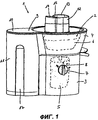
фиг.1 - перспективное изображение соковой центрифуги, имеющей предлагаемую в изобретении фиксацию корпуса;figure 1 is a perspective image of a juice centrifuge having a housing fixation according to the invention;
фиг.2 - разрез соковой центрифуги по фиг.1 с предлагаемой в изобретении фиксацией корпуса;figure 2 is a section of the juice centrifuge of figure 1 with the proposed invention the fixation of the housing;
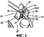
фиг.3 - частичное перспективное изображение предлагаемой в изобретении фиксации корпуса;figure 3 is a partial perspective image proposed in the invention the fixation of the housing;
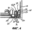
фиг.4 - разрез фиксации корпуса по фиг.3 с запорным элементом в освобожденном положении;figure 4 is a sectional view of the fixation of the housing of figure 3 with a locking element in the released position;
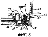
фиг.5 - разрез фиксации корпуса по фиг.3 с запорным элементом в запертом положении.figure 5 is a sectional view of the fixation of the housing of figure 3 with the locking element in the locked position.
Осуществление изобретенияThe implementation of the invention
Изображенная на фиг.1 соковая центрифуга 1 имеет корпус 2, состоящий из полой цилиндрической нижней секции 3 и конической верхней секции 4. В нижней секции 3 находится приводной двигатель 5, вращающий рабочий орган 6, который расположен в верхней секции 4. Они закрыты от взгляда и изображены схематически. Электродвигателем 5 управляет поворотный орган управления 7. Орган управления 7 выполнен в виде поворотной головки и расположен на передней стенке полой цилиндрической нижней секции 3. В изображенном на чертеже положении органа управления 7 риска 8 соответствует коммутационному положению выключателя "0", при котором бытовой прибор выключен. В расположенном правее по часовой стрелке коммутационном положении "I" органа управления 7 соковая центрифуга 1 работает с малой скоростью вращения, а в расположенном еще правее коммутационном положении "II" органа управления 7 соковая центрифуга 1 работает с большой скоростью вращения. В коммутационном положении "А", расположенном против часовой стрелки левее коммутационного положения "0", орган управления 7 находится в положении деблокировки 18, при котором крышку 9 прибора можно открыть, что позволяет извлечь рабочий орган 6. Крышка 9 прибора лежит заподлицо с верхним краем корпуса 2 и закрывает также верхнее отверстие 10 сборника выжимок 11. В крышке 9 имеется загрузочная трубка 12, через которую кусочки пищевых продуктов могут загружаться в корпус 2 на рабочий орган 6. Загрузочная трубка 12 состоит из двух частей, т.е. из двух загрузочных патрубков 13 и 14 различного сечения, разделенных стенкой 15 трубки. Загрузочные патрубки 13 и 14 имеют круглое или овальное сечение, причем сечение загрузочного патрубка 13 больше сечения загрузочного патрубка 14. Рабочий орган 6 разделяет загружаемые через патрубок 13 или 14 кусочки пищевого продукта на сок и преимущественно твердые выжимки. После разделения выжимки попадают в сборник выжимок 11, а сок - в приемник 16. С двух противолежащих сторон сборника выжимок 11 имеются два продолговатых корытообразных углубления 17 для захвата.The juice centrifuge 1 shown in FIG. 1 has a
Изображенный на фиг.2 в разрезе корпус 2 имеет первую секцию 18 корпуса и вторую секцию 19 корпуса. Первая секция 18 корпуса образует дно соковой центрифуги 1, в котором предусмотрены отверстия 20 для прохода воздуха, охлаждающего двигатель 5. Двигатель 5 расположен в стакане 21, установленном в гнезде 22, приформованном в первой секции 18 корпуса. Гнездо 22 тянется в виде кольцеобразного выступа из внутренней стороны первой секции 18 корпуса в полость 23 для стакана 21 с двигателем 5. Для того чтобы стакан 21 самоцентрировался в кольцеобразном гнезде 22, верхняя кромка гнезда 22 имеет фаску 24. Выполненная в виде опорной плиты первая секция 18 корпуса имеет фиксатор 25. Фиксатор 25 выполнен в виде приформованной к первой секции 18 корпуса планки с пружинящим стопорным крючком 26. В застопоренном положении стопорный крючок 26 фиксатора 25 заскакивает за контрфиксатор 27 на второй секции 19 корпуса. Контрфиксатор 27 выполнен в виде стопорного зубца 28. Для дополнительного прочного соединения первой секции 18 со второй секцией 19 корпуса на первой секции 18 корпуса приформована стопорная выемка 29, в которую входит стопорный зубец 28 второй секции 19 корпуса. Первая секция 18 соединяется со второй секцией 19 корпуса в нескольких местах с помощью нескольких фиксаторов 25 и контрфиксаторов 27. Эти места соединения распределены по окружности корпуса 2 приблизительно равномерно.2, a sectional view of the
Действие предлагаемого в изобретении запорного элемента 30 показано на фиг.3-5. На фиг.3 в перспективном изображении, а на фиг.4 в разрезе изображено соединение фиксатора 25 и контрфиксатора 27 при освобожденном положении запорного элемента 30. Запорный элемент 30 выполнен в виде планки. Первый конец 31 запорного элемента 30 приформован на первой секции 18 корпуса. Второй, свободный конец 32 запорного элемента 30 направлен вертикально вверх и расположен в изображенном на фиг.3 освобожденном положении практически параллельно фиксатору 25, не заходя в паз 33, приформованный на верхнем конце фиксатора 25 с противоположной стороны от стопорного крючка 26. В зависимости от формы второго, свободного конца 32 запорного элемента 30 паз 33 может быть выполнен и в виде стопорного зубца 34 соответствующей формы.The action proposed in the invention of the locking
На фиг.5 представлено в разрезе соединение фиксатора 25 и контрфиксатора 27 при запертом положении запорного элемента 30. Первый конец 31 запорного элемента 30 приформован на первой секции 18 корпуса так, что он из своего положения, практически параллельного фиксатору 25, отогнут на фиг.5 по часовой стрелке вправо. В этом отогнутом вправо положении второй конец 32 запорного элемента 30 входит в стопорный зубец 34 фиксатора 25 и, таким образом, закрепляет фиксатор 25 в его положении. Самопроизвольное отклонение фиксатора 25 влево по фиг.5, против часовой стрелки, уже невозможно, что надежно препятствует выскальзыванию стопорного крючка 26 фиксатора 25 из стопорного зубца 28 контрфиксатора 27.Figure 5 shows a sectional view of the connection of the
Первая секция 18 корпуса, несущая запорный элемент 30, имеет первое отверстие 35 в стенке. Первое отверстие 35 в стенке расположено на стороне запорного элемента 30, противоположной фиксатору 25. Через это отверстие 35 в стенке можно ввести инструмент, например шлицевую отвертку. При отклонении лезвия шлицевой отвертки (не изображена) на фиг.4 по часовой стрелке вправо запорный элемент 30 отклоняется из своего освобожденного положения (фиг.3 и 4) в направлении фиксатора 25 и второй конец 32 запорного элемента 30 вдавливается в стопорный зубец 34 фиксатора 25, пока запорный элемент 30 не зафиксируется в своем запертом положении (фиг.5).The
Первая секция 18 корпуса, несущая запорный элемент 30, имеет второе отверстие 36 в стенке. Второе отверстие 36 в стенке расположено между фиксатором 25 и запорным элементом 30. Через это отверстие 36 в стенке можно ввести инструмент, например шлицевую отвертку. При отклонении лезвия шлицевой отвертки (не изображена) на фиг.5 против часовой стрелки влево запорный элемент 30 отходит от своего запертого положения (фиг.5) в фиксаторе 25 и второй конец 32 запорного элемента 30 выводится из стопорного зубца 34 фиксатора 25, пока запорный элемент 30 не перейдет из запертого в освобожденное положение.The
Первая секция 18 корпуса, несущая запорный элемент 30, имеет третье отверстие 37 в стенке. Третье отверстие 37 в стенке расположено на стороне фиксатора 25, противоположной запорному элемента 30. Через это отверстие 37 в стенке можно ввести инструмент, например шлицевую отвертку. При отклонении лезвия шлицевой отвертки (не изображена) на фиг.4 или 5 против часовой стрелки влево фиксатор 25 выходит из своего запертого в контрфиксаторе 27 положения (фиг.4 и 5) и освобождается от него, так что первая секция 18 корпуса отделяется от второй секции 19 корпуса. Этим способом осуществляется неразрушающий демонтаж секций 18 и 19 корпуса.The
Claims (12)
Applications Claiming Priority (2)
| Application Number | Priority Date | Filing Date | Title |
|---|---|---|---|
| DE102004015915.7 | 2004-03-31 | ||
| DE200410015915 DE102004015915A1 (en) | 2004-03-31 | 2004-03-31 | Household appliance with latching and counter-latching means |
Publications (2)
| Publication Number | Publication Date |
|---|---|
| RU2006132915A RU2006132915A (en) | 2008-05-10 |
| RU2376503C2 true RU2376503C2 (en) | 2009-12-20 |
Family
ID=34965646
Family Applications (1)
| Application Number | Title | Priority Date | Filing Date |
|---|---|---|---|
| RU2006132915A RU2376503C2 (en) | 2004-03-31 | 2005-03-30 | Household appliance with fixation facilities |
Country Status (10)
| Country | Link |
|---|---|
| US (1) | US7472646B2 (en) |
| EP (1) | EP1733148B1 (en) |
| CN (1) | CN1938523B (en) |
| AT (1) | ATE423914T1 (en) |
| DE (2) | DE102004015915A1 (en) |
| ES (1) | ES2321738T3 (en) |
| PL (1) | PL1733148T3 (en) |
| RU (1) | RU2376503C2 (en) |
| SI (1) | SI1733148T1 (en) |
| WO (1) | WO2005095806A1 (en) |
Families Citing this family (7)
| Publication number | Priority date | Publication date | Assignee | Title |
|---|---|---|---|---|
| DE10261367A1 (en) * | 2002-12-30 | 2004-07-08 | BSH Bosch und Siemens Hausgeräte GmbH | Cup arrangement for a mixing comminution device |
| DE102005023157A1 (en) * | 2005-05-19 | 2006-11-23 | BSH Bosch und Siemens Hausgeräte GmbH | Floor fixing for household appliances |
| US20090235831A1 (en) * | 2008-03-18 | 2009-09-24 | Arthur Nisonov | Self-Cleansing Juicer System |
| US9260893B1 (en) * | 2009-04-16 | 2016-02-16 | Interlock Usa, Inc. | Window lock |
| EP2248449A1 (en) * | 2009-05-08 | 2010-11-10 | Koninklijke Philips Electronics N.V. | Kitchen appliance |
| TR201721473T3 (en) | 2013-12-04 | 2018-01-22 | Arcelik As | Household appliance with locking element. |
| CN107874632B (en) * | 2016-09-30 | 2024-04-12 | 浙江绍兴苏泊尔生活电器有限公司 | Cooking utensil's casing and have its cooking utensil |
Citations (3)
| Publication number | Priority date | Publication date | Assignee | Title |
|---|---|---|---|---|
| US4479737A (en) * | 1982-02-01 | 1984-10-30 | Bergh Bros. Co., Inc. | Positive interlock |
| SU1275135A1 (en) * | 1979-12-03 | 1986-12-07 | Специальное Конструкторское Бюро Министерства Высшего И Среднего Специального Образования Ссср | Joint of components |
| DE10142508A1 (en) * | 2001-08-30 | 2003-03-27 | Bsh Bosch Siemens Hausgeraete | Locking device and food processor equipped with this |
Family Cites Families (8)
| Publication number | Priority date | Publication date | Assignee | Title |
|---|---|---|---|---|
| DE3636176A1 (en) * | 1986-10-24 | 1988-05-05 | Bayerische Motoren Werke Ag | Fastening element for the releasable connection of two components |
| CN2117490U (en) * | 1992-03-14 | 1992-09-30 | 黄家华 | Multifunctional panel joint |
| DE19540823C2 (en) * | 1995-11-02 | 1998-08-20 | Daimler Benz Ag | Fastening device for a noise capsule part |
| DE10016300A1 (en) * | 2000-03-31 | 2001-10-04 | Bsh Bosch Siemens Hausgeraete | Juice centrifuge |
| DE10016297A1 (en) * | 2000-03-31 | 2001-10-04 | Bsh Bosch Siemens Hausgeraete | Strainer attachment for food processor has two or more straining blades on hub provided with rib protrusions on side facing sieve and with cutting edges at trailing end |
| DE10142246A1 (en) * | 2001-08-29 | 2003-05-08 | Bsh Bosch Siemens Hausgeraete | Juicer |
| DE10142507A1 (en) * | 2001-08-30 | 2003-03-27 | Bsh Bosch Siemens Hausgeraete | Juicer |
| DE10142506A1 (en) * | 2001-08-30 | 2003-03-20 | Bsh Bosch Siemens Hausgeraete | Juicer |
-
2004
- 2004-03-31 DE DE200410015915 patent/DE102004015915A1/en not_active Withdrawn
-
2005
- 2005-03-30 PL PL05737868T patent/PL1733148T3/en unknown
- 2005-03-30 DE DE200550006694 patent/DE502005006694D1/de not_active Expired - Lifetime
- 2005-03-30 US US11/547,022 patent/US7472646B2/en not_active Expired - Fee Related
- 2005-03-30 RU RU2006132915A patent/RU2376503C2/en active
- 2005-03-30 ES ES05737868T patent/ES2321738T3/en not_active Expired - Lifetime
- 2005-03-30 WO PCT/EP2005/051435 patent/WO2005095806A1/en not_active Ceased
- 2005-03-30 SI SI200530686T patent/SI1733148T1/en unknown
- 2005-03-30 AT AT05737868T patent/ATE423914T1/en active
- 2005-03-30 EP EP05737868A patent/EP1733148B1/en not_active Expired - Lifetime
- 2005-03-30 CN CN2005800100901A patent/CN1938523B/en not_active Expired - Fee Related
Patent Citations (3)
| Publication number | Priority date | Publication date | Assignee | Title |
|---|---|---|---|---|
| SU1275135A1 (en) * | 1979-12-03 | 1986-12-07 | Специальное Конструкторское Бюро Министерства Высшего И Среднего Специального Образования Ссср | Joint of components |
| US4479737A (en) * | 1982-02-01 | 1984-10-30 | Bergh Bros. Co., Inc. | Positive interlock |
| DE10142508A1 (en) * | 2001-08-30 | 2003-03-27 | Bsh Bosch Siemens Hausgeraete | Locking device and food processor equipped with this |
Also Published As
| Publication number | Publication date |
|---|---|
| WO2005095806A1 (en) | 2005-10-13 |
| ATE423914T1 (en) | 2009-03-15 |
| US20070205610A1 (en) | 2007-09-06 |
| CN1938523B (en) | 2010-05-05 |
| EP1733148A1 (en) | 2006-12-20 |
| DE102004015915A1 (en) | 2005-10-20 |
| RU2006132915A (en) | 2008-05-10 |
| EP1733148B1 (en) | 2009-02-25 |
| ES2321738T3 (en) | 2009-06-10 |
| CN1938523A (en) | 2007-03-28 |
| DE502005006694D1 (en) | 2009-04-09 |
| PL1733148T3 (en) | 2009-07-31 |
| US7472646B2 (en) | 2009-01-06 |
| SI1733148T1 (en) | 2009-08-31 |
Similar Documents
| Publication | Publication Date | Title |
|---|---|---|
| RU2376503C2 (en) | Household appliance with fixation facilities | |
| EP2861792B1 (en) | Laundry treatment device with door assembly | |
| KR20110112348A (en) | Separation system for kitchen utensils | |
| US10799070B2 (en) | Mixing tool lock for a kitchen appliance | |
| RU2526098C2 (en) | Device for connection and disconnection of cooking vessel handle | |
| AU780934B2 (en) | Food processing appliance with storable tool support | |
| HUP0103525A2 (en) | Removable food processing tool support system for blenders, food processors, grinders and similar apparatus | |
| KR20080002763A (en) | Household appliance with fixture | |
| EP4042914B1 (en) | Food processor and cutter set mounting structure thereof, and stirring cup | |
| HU222863B1 (en) | Coupling device for an appliance for domestic use | |
| CN113669975A (en) | Water storage box and refrigerator | |
| KR101941059B1 (en) | Automatic washing apparatus of a gun barrel | |
| CN118512115A (en) | Food processor and knife set mounting structure and stirring cup thereof | |
| RU2370198C2 (en) | Household device with central control | |
| CN108742416B (en) | Automatic door opening system and household appliance | |
| CN209202929U (en) | Cooking cup and cooking machine | |
| RU2374973C2 (en) | Domestic appliance with safety device | |
| WO2017174781A1 (en) | A household appliance with improved safety | |
| CN110353531A (en) | Stir cup assembly and the cooking machine including the stirring cup assembly | |
| CN103313637A (en) | Removable device for gripping a cooking utensil | |
| RU2452358C2 (en) | Kitchen machine with the releasing button on cover | |
| CN120036616B (en) | Raw juice machine convenient to assemble and disassemble | |
| KR100269469B1 (en) | Leg slidimg apparatus of built-in dish washer | |
| CN111904304B (en) | Handles and pots | |
| CN223731271U (en) | Kitchen equipment |
Legal Events
| Date | Code | Title | Description |
|---|---|---|---|
| PD4A | Correction of name of patent owner |