RU2376142C2 - Method and device for forming tight connection and use of above method - Google Patents
Method and device for forming tight connection and use of above method Download PDFInfo
- Publication number
- RU2376142C2 RU2376142C2 RU2006147011A RU2006147011A RU2376142C2 RU 2376142 C2 RU2376142 C2 RU 2376142C2 RU 2006147011 A RU2006147011 A RU 2006147011A RU 2006147011 A RU2006147011 A RU 2006147011A RU 2376142 C2 RU2376142 C2 RU 2376142C2
- Authority
- RU
- Russia
- Prior art keywords
- section
- web
- layers
- support
- recesses
- Prior art date
Links
Images

Classifications
-
- B—PERFORMING OPERATIONS; TRANSPORTING
- B29—WORKING OF PLASTICS; WORKING OF SUBSTANCES IN A PLASTIC STATE IN GENERAL
- B29C—SHAPING OR JOINING OF PLASTICS; SHAPING OF MATERIAL IN A PLASTIC STATE, NOT OTHERWISE PROVIDED FOR; AFTER-TREATMENT OF THE SHAPED PRODUCTS, e.g. REPAIRING
- B29C66/00—General aspects of processes or apparatus for joining preformed parts
- B29C66/80—General aspects of machine operations or constructions and parts thereof
-
- B—PERFORMING OPERATIONS; TRANSPORTING
- B65—CONVEYING; PACKING; STORING; HANDLING THIN OR FILAMENTARY MATERIAL
- B65B—MACHINES, APPARATUS OR DEVICES FOR, OR METHODS OF, PACKAGING ARTICLES OR MATERIALS; UNPACKING
- B65B51/00—Devices for, or methods of, sealing or securing package folds or closures; Devices for gathering or twisting wrappers, or necks of bags
- B65B51/10—Applying or generating heat or pressure or combinations thereof
- B65B51/26—Devices specially adapted for producing transverse or longitudinal seams in webs or tubes
- B65B51/30—Devices, e.g. jaws, for applying pressure and heat, e.g. for subdividing filled tubes
-
- B—PERFORMING OPERATIONS; TRANSPORTING
- B29—WORKING OF PLASTICS; WORKING OF SUBSTANCES IN A PLASTIC STATE IN GENERAL
- B29C—SHAPING OR JOINING OF PLASTICS; SHAPING OF MATERIAL IN A PLASTIC STATE, NOT OTHERWISE PROVIDED FOR; AFTER-TREATMENT OF THE SHAPED PRODUCTS, e.g. REPAIRING
- B29C65/00—Joining or sealing of preformed parts, e.g. welding of plastics materials; Apparatus therefor
- B29C65/02—Joining or sealing of preformed parts, e.g. welding of plastics materials; Apparatus therefor by heating, with or without pressure
- B29C65/18—Joining or sealing of preformed parts, e.g. welding of plastics materials; Apparatus therefor by heating, with or without pressure using heated tools
- B29C65/24—Joining or sealing of preformed parts, e.g. welding of plastics materials; Apparatus therefor by heating, with or without pressure using heated tools characterised by the means for heating the tool
- B29C65/30—Electrical means
- B29C65/305—Electrical means involving the use of cartridge heaters
-
- B—PERFORMING OPERATIONS; TRANSPORTING
- B29—WORKING OF PLASTICS; WORKING OF SUBSTANCES IN A PLASTIC STATE IN GENERAL
- B29C—SHAPING OR JOINING OF PLASTICS; SHAPING OF MATERIAL IN A PLASTIC STATE, NOT OTHERWISE PROVIDED FOR; AFTER-TREATMENT OF THE SHAPED PRODUCTS, e.g. REPAIRING
- B29C65/00—Joining or sealing of preformed parts, e.g. welding of plastics materials; Apparatus therefor
- B29C65/48—Joining or sealing of preformed parts, e.g. welding of plastics materials; Apparatus therefor using adhesives, i.e. using supplementary joining material; solvent bonding
- B29C65/50—Joining or sealing of preformed parts, e.g. welding of plastics materials; Apparatus therefor using adhesives, i.e. using supplementary joining material; solvent bonding using adhesive tape, e.g. thermoplastic tape; using threads or the like
- B29C65/5057—Joining or sealing of preformed parts, e.g. welding of plastics materials; Apparatus therefor using adhesives, i.e. using supplementary joining material; solvent bonding using adhesive tape, e.g. thermoplastic tape; using threads or the like positioned between the surfaces to be joined
-
- B—PERFORMING OPERATIONS; TRANSPORTING
- B29—WORKING OF PLASTICS; WORKING OF SUBSTANCES IN A PLASTIC STATE IN GENERAL
- B29C—SHAPING OR JOINING OF PLASTICS; SHAPING OF MATERIAL IN A PLASTIC STATE, NOT OTHERWISE PROVIDED FOR; AFTER-TREATMENT OF THE SHAPED PRODUCTS, e.g. REPAIRING
- B29C65/00—Joining or sealing of preformed parts, e.g. welding of plastics materials; Apparatus therefor
- B29C65/48—Joining or sealing of preformed parts, e.g. welding of plastics materials; Apparatus therefor using adhesives, i.e. using supplementary joining material; solvent bonding
- B29C65/50—Joining or sealing of preformed parts, e.g. welding of plastics materials; Apparatus therefor using adhesives, i.e. using supplementary joining material; solvent bonding using adhesive tape, e.g. thermoplastic tape; using threads or the like
- B29C65/5064—Joining or sealing of preformed parts, e.g. welding of plastics materials; Apparatus therefor using adhesives, i.e. using supplementary joining material; solvent bonding using adhesive tape, e.g. thermoplastic tape; using threads or the like of particular form, e.g. being C-shaped, T-shaped
- B29C65/5071—Joining or sealing of preformed parts, e.g. welding of plastics materials; Apparatus therefor using adhesives, i.e. using supplementary joining material; solvent bonding using adhesive tape, e.g. thermoplastic tape; using threads or the like of particular form, e.g. being C-shaped, T-shaped and being composed by one single element
-
- B—PERFORMING OPERATIONS; TRANSPORTING
- B29—WORKING OF PLASTICS; WORKING OF SUBSTANCES IN A PLASTIC STATE IN GENERAL
- B29C—SHAPING OR JOINING OF PLASTICS; SHAPING OF MATERIAL IN A PLASTIC STATE, NOT OTHERWISE PROVIDED FOR; AFTER-TREATMENT OF THE SHAPED PRODUCTS, e.g. REPAIRING
- B29C66/00—General aspects of processes or apparatus for joining preformed parts
- B29C66/01—General aspects dealing with the joint area or with the area to be joined
- B29C66/05—Particular design of joint configurations
- B29C66/10—Particular design of joint configurations particular design of the joint cross-sections
- B29C66/11—Joint cross-sections comprising a single joint-segment, i.e. one of the parts to be joined comprising a single joint-segment in the joint cross-section
- B29C66/112—Single lapped joints
- B29C66/1122—Single lap to lap joints, i.e. overlap joints
-
- B—PERFORMING OPERATIONS; TRANSPORTING
- B29—WORKING OF PLASTICS; WORKING OF SUBSTANCES IN A PLASTIC STATE IN GENERAL
- B29C—SHAPING OR JOINING OF PLASTICS; SHAPING OF MATERIAL IN A PLASTIC STATE, NOT OTHERWISE PROVIDED FOR; AFTER-TREATMENT OF THE SHAPED PRODUCTS, e.g. REPAIRING
- B29C66/00—General aspects of processes or apparatus for joining preformed parts
- B29C66/01—General aspects dealing with the joint area or with the area to be joined
- B29C66/05—Particular design of joint configurations
- B29C66/20—Particular design of joint configurations particular design of the joint lines, e.g. of the weld lines
- B29C66/24—Particular design of joint configurations particular design of the joint lines, e.g. of the weld lines said joint lines being closed or non-straight
- B29C66/244—Particular design of joint configurations particular design of the joint lines, e.g. of the weld lines said joint lines being closed or non-straight said joint lines being non-straight, e.g. forming non-closed contours
-
- B—PERFORMING OPERATIONS; TRANSPORTING
- B29—WORKING OF PLASTICS; WORKING OF SUBSTANCES IN A PLASTIC STATE IN GENERAL
- B29C—SHAPING OR JOINING OF PLASTICS; SHAPING OF MATERIAL IN A PLASTIC STATE, NOT OTHERWISE PROVIDED FOR; AFTER-TREATMENT OF THE SHAPED PRODUCTS, e.g. REPAIRING
- B29C66/00—General aspects of processes or apparatus for joining preformed parts
- B29C66/01—General aspects dealing with the joint area or with the area to be joined
- B29C66/05—Particular design of joint configurations
- B29C66/306—Applying a mark during joining
-
- B—PERFORMING OPERATIONS; TRANSPORTING
- B29—WORKING OF PLASTICS; WORKING OF SUBSTANCES IN A PLASTIC STATE IN GENERAL
- B29C—SHAPING OR JOINING OF PLASTICS; SHAPING OF MATERIAL IN A PLASTIC STATE, NOT OTHERWISE PROVIDED FOR; AFTER-TREATMENT OF THE SHAPED PRODUCTS, e.g. REPAIRING
- B29C66/00—General aspects of processes or apparatus for joining preformed parts
- B29C66/40—General aspects of joining substantially flat articles, e.g. plates, sheets or web-like materials; Making flat seams in tubular or hollow articles; Joining single elements to substantially flat surfaces
- B29C66/41—Joining substantially flat articles ; Making flat seams in tubular or hollow articles
- B29C66/43—Joining a relatively small portion of the surface of said articles
-
- B—PERFORMING OPERATIONS; TRANSPORTING
- B29—WORKING OF PLASTICS; WORKING OF SUBSTANCES IN A PLASTIC STATE IN GENERAL
- B29C—SHAPING OR JOINING OF PLASTICS; SHAPING OF MATERIAL IN A PLASTIC STATE, NOT OTHERWISE PROVIDED FOR; AFTER-TREATMENT OF THE SHAPED PRODUCTS, e.g. REPAIRING
- B29C66/00—General aspects of processes or apparatus for joining preformed parts
- B29C66/40—General aspects of joining substantially flat articles, e.g. plates, sheets or web-like materials; Making flat seams in tubular or hollow articles; Joining single elements to substantially flat surfaces
- B29C66/47—Joining single elements to sheets, plates or other substantially flat surfaces
- B29C66/472—Joining single elements to sheets, plates or other substantially flat surfaces said single elements being substantially flat
-
- B—PERFORMING OPERATIONS; TRANSPORTING
- B29—WORKING OF PLASTICS; WORKING OF SUBSTANCES IN A PLASTIC STATE IN GENERAL
- B29C—SHAPING OR JOINING OF PLASTICS; SHAPING OF MATERIAL IN A PLASTIC STATE, NOT OTHERWISE PROVIDED FOR; AFTER-TREATMENT OF THE SHAPED PRODUCTS, e.g. REPAIRING
- B29C66/00—General aspects of processes or apparatus for joining preformed parts
- B29C66/70—General aspects of processes or apparatus for joining preformed parts characterised by the composition, physical properties or the structure of the material of the parts to be joined; Joining with non-plastics material
- B29C66/73—General aspects of processes or apparatus for joining preformed parts characterised by the composition, physical properties or the structure of the material of the parts to be joined; Joining with non-plastics material characterised by the intensive physical properties of the material of the parts to be joined, by the optical properties of the material of the parts to be joined, by the extensive physical properties of the parts to be joined, by the state of the material of the parts to be joined or by the material of the parts to be joined being a thermoplastic or a thermoset
- B29C66/739—General aspects of processes or apparatus for joining preformed parts characterised by the composition, physical properties or the structure of the material of the parts to be joined; Joining with non-plastics material characterised by the intensive physical properties of the material of the parts to be joined, by the optical properties of the material of the parts to be joined, by the extensive physical properties of the parts to be joined, by the state of the material of the parts to be joined or by the material of the parts to be joined being a thermoplastic or a thermoset characterised by the material of the parts to be joined being a thermoplastic or a thermoset
- B29C66/7392—General aspects of processes or apparatus for joining preformed parts characterised by the composition, physical properties or the structure of the material of the parts to be joined; Joining with non-plastics material characterised by the intensive physical properties of the material of the parts to be joined, by the optical properties of the material of the parts to be joined, by the extensive physical properties of the parts to be joined, by the state of the material of the parts to be joined or by the material of the parts to be joined being a thermoplastic or a thermoset characterised by the material of the parts to be joined being a thermoplastic or a thermoset characterised by the material of at least one of the parts being a thermoplastic
- B29C66/73921—General aspects of processes or apparatus for joining preformed parts characterised by the composition, physical properties or the structure of the material of the parts to be joined; Joining with non-plastics material characterised by the intensive physical properties of the material of the parts to be joined, by the optical properties of the material of the parts to be joined, by the extensive physical properties of the parts to be joined, by the state of the material of the parts to be joined or by the material of the parts to be joined being a thermoplastic or a thermoset characterised by the material of the parts to be joined being a thermoplastic or a thermoset characterised by the material of at least one of the parts being a thermoplastic characterised by the materials of both parts being thermoplastics
-
- B—PERFORMING OPERATIONS; TRANSPORTING
- B29—WORKING OF PLASTICS; WORKING OF SUBSTANCES IN A PLASTIC STATE IN GENERAL
- B29C—SHAPING OR JOINING OF PLASTICS; SHAPING OF MATERIAL IN A PLASTIC STATE, NOT OTHERWISE PROVIDED FOR; AFTER-TREATMENT OF THE SHAPED PRODUCTS, e.g. REPAIRING
- B29C66/00—General aspects of processes or apparatus for joining preformed parts
- B29C66/80—General aspects of machine operations or constructions and parts thereof
- B29C66/81—General aspects of the pressing elements, i.e. the elements applying pressure on the parts to be joined in the area to be joined, e.g. the welding jaws or clamps
- B29C66/814—General aspects of the pressing elements, i.e. the elements applying pressure on the parts to be joined in the area to be joined, e.g. the welding jaws or clamps characterised by the design of the pressing elements, e.g. of the welding jaws or clamps
- B29C66/8141—General aspects of the pressing elements, i.e. the elements applying pressure on the parts to be joined in the area to be joined, e.g. the welding jaws or clamps characterised by the design of the pressing elements, e.g. of the welding jaws or clamps characterised by the surface geometry of the part of the pressing elements, e.g. welding jaws or clamps, coming into contact with the parts to be joined
- B29C66/81411—General aspects of the pressing elements, i.e. the elements applying pressure on the parts to be joined in the area to be joined, e.g. the welding jaws or clamps characterised by the design of the pressing elements, e.g. of the welding jaws or clamps characterised by the surface geometry of the part of the pressing elements, e.g. welding jaws or clamps, coming into contact with the parts to be joined characterised by its cross-section, e.g. transversal or longitudinal, being non-flat
- B29C66/81415—General aspects of the pressing elements, i.e. the elements applying pressure on the parts to be joined in the area to be joined, e.g. the welding jaws or clamps characterised by the design of the pressing elements, e.g. of the welding jaws or clamps characterised by the surface geometry of the part of the pressing elements, e.g. welding jaws or clamps, coming into contact with the parts to be joined characterised by its cross-section, e.g. transversal or longitudinal, being non-flat being bevelled
- B29C66/81419—General aspects of the pressing elements, i.e. the elements applying pressure on the parts to be joined in the area to be joined, e.g. the welding jaws or clamps characterised by the design of the pressing elements, e.g. of the welding jaws or clamps characterised by the surface geometry of the part of the pressing elements, e.g. welding jaws or clamps, coming into contact with the parts to be joined characterised by its cross-section, e.g. transversal or longitudinal, being non-flat being bevelled and flat
-
- B—PERFORMING OPERATIONS; TRANSPORTING
- B29—WORKING OF PLASTICS; WORKING OF SUBSTANCES IN A PLASTIC STATE IN GENERAL
- B29C—SHAPING OR JOINING OF PLASTICS; SHAPING OF MATERIAL IN A PLASTIC STATE, NOT OTHERWISE PROVIDED FOR; AFTER-TREATMENT OF THE SHAPED PRODUCTS, e.g. REPAIRING
- B29C66/00—General aspects of processes or apparatus for joining preformed parts
- B29C66/80—General aspects of machine operations or constructions and parts thereof
- B29C66/81—General aspects of the pressing elements, i.e. the elements applying pressure on the parts to be joined in the area to be joined, e.g. the welding jaws or clamps
- B29C66/814—General aspects of the pressing elements, i.e. the elements applying pressure on the parts to be joined in the area to be joined, e.g. the welding jaws or clamps characterised by the design of the pressing elements, e.g. of the welding jaws or clamps
- B29C66/8141—General aspects of the pressing elements, i.e. the elements applying pressure on the parts to be joined in the area to be joined, e.g. the welding jaws or clamps characterised by the design of the pressing elements, e.g. of the welding jaws or clamps characterised by the surface geometry of the part of the pressing elements, e.g. welding jaws or clamps, coming into contact with the parts to be joined
- B29C66/81431—General aspects of the pressing elements, i.e. the elements applying pressure on the parts to be joined in the area to be joined, e.g. the welding jaws or clamps characterised by the design of the pressing elements, e.g. of the welding jaws or clamps characterised by the surface geometry of the part of the pressing elements, e.g. welding jaws or clamps, coming into contact with the parts to be joined comprising a single cavity, e.g. a groove
-
- B—PERFORMING OPERATIONS; TRANSPORTING
- B29—WORKING OF PLASTICS; WORKING OF SUBSTANCES IN A PLASTIC STATE IN GENERAL
- B29C—SHAPING OR JOINING OF PLASTICS; SHAPING OF MATERIAL IN A PLASTIC STATE, NOT OTHERWISE PROVIDED FOR; AFTER-TREATMENT OF THE SHAPED PRODUCTS, e.g. REPAIRING
- B29C66/00—General aspects of processes or apparatus for joining preformed parts
- B29C66/80—General aspects of machine operations or constructions and parts thereof
- B29C66/83—General aspects of machine operations or constructions and parts thereof characterised by the movement of the joining or pressing tools
- B29C66/832—Reciprocating joining or pressing tools
- B29C66/8322—Joining or pressing tools reciprocating along one axis
-
- B—PERFORMING OPERATIONS; TRANSPORTING
- B29—WORKING OF PLASTICS; WORKING OF SUBSTANCES IN A PLASTIC STATE IN GENERAL
- B29C—SHAPING OR JOINING OF PLASTICS; SHAPING OF MATERIAL IN A PLASTIC STATE, NOT OTHERWISE PROVIDED FOR; AFTER-TREATMENT OF THE SHAPED PRODUCTS, e.g. REPAIRING
- B29C65/00—Joining or sealing of preformed parts, e.g. welding of plastics materials; Apparatus therefor
- B29C65/02—Joining or sealing of preformed parts, e.g. welding of plastics materials; Apparatus therefor by heating, with or without pressure
- B29C65/08—Joining or sealing of preformed parts, e.g. welding of plastics materials; Apparatus therefor by heating, with or without pressure using ultrasonic vibrations
-
- B—PERFORMING OPERATIONS; TRANSPORTING
- B29—WORKING OF PLASTICS; WORKING OF SUBSTANCES IN A PLASTIC STATE IN GENERAL
- B29C—SHAPING OR JOINING OF PLASTICS; SHAPING OF MATERIAL IN A PLASTIC STATE, NOT OTHERWISE PROVIDED FOR; AFTER-TREATMENT OF THE SHAPED PRODUCTS, e.g. REPAIRING
- B29C66/00—General aspects of processes or apparatus for joining preformed parts
- B29C66/70—General aspects of processes or apparatus for joining preformed parts characterised by the composition, physical properties or the structure of the material of the parts to be joined; Joining with non-plastics material
- B29C66/71—General aspects of processes or apparatus for joining preformed parts characterised by the composition, physical properties or the structure of the material of the parts to be joined; Joining with non-plastics material characterised by the composition of the plastics material of the parts to be joined
-
- B—PERFORMING OPERATIONS; TRANSPORTING
- B29—WORKING OF PLASTICS; WORKING OF SUBSTANCES IN A PLASTIC STATE IN GENERAL
- B29C—SHAPING OR JOINING OF PLASTICS; SHAPING OF MATERIAL IN A PLASTIC STATE, NOT OTHERWISE PROVIDED FOR; AFTER-TREATMENT OF THE SHAPED PRODUCTS, e.g. REPAIRING
- B29C66/00—General aspects of processes or apparatus for joining preformed parts
- B29C66/80—General aspects of machine operations or constructions and parts thereof
- B29C66/81—General aspects of the pressing elements, i.e. the elements applying pressure on the parts to be joined in the area to be joined, e.g. the welding jaws or clamps
- B29C66/814—General aspects of the pressing elements, i.e. the elements applying pressure on the parts to be joined in the area to be joined, e.g. the welding jaws or clamps characterised by the design of the pressing elements, e.g. of the welding jaws or clamps
- B29C66/8141—General aspects of the pressing elements, i.e. the elements applying pressure on the parts to be joined in the area to be joined, e.g. the welding jaws or clamps characterised by the design of the pressing elements, e.g. of the welding jaws or clamps characterised by the surface geometry of the part of the pressing elements, e.g. welding jaws or clamps, coming into contact with the parts to be joined
- B29C66/81411—General aspects of the pressing elements, i.e. the elements applying pressure on the parts to be joined in the area to be joined, e.g. the welding jaws or clamps characterised by the design of the pressing elements, e.g. of the welding jaws or clamps characterised by the surface geometry of the part of the pressing elements, e.g. welding jaws or clamps, coming into contact with the parts to be joined characterised by its cross-section, e.g. transversal or longitudinal, being non-flat
- B29C66/81421—General aspects of the pressing elements, i.e. the elements applying pressure on the parts to be joined in the area to be joined, e.g. the welding jaws or clamps characterised by the design of the pressing elements, e.g. of the welding jaws or clamps characterised by the surface geometry of the part of the pressing elements, e.g. welding jaws or clamps, coming into contact with the parts to be joined characterised by its cross-section, e.g. transversal or longitudinal, being non-flat being convex or concave
- B29C66/81423—General aspects of the pressing elements, i.e. the elements applying pressure on the parts to be joined in the area to be joined, e.g. the welding jaws or clamps characterised by the design of the pressing elements, e.g. of the welding jaws or clamps characterised by the surface geometry of the part of the pressing elements, e.g. welding jaws or clamps, coming into contact with the parts to be joined characterised by its cross-section, e.g. transversal or longitudinal, being non-flat being convex or concave being concave
-
- B—PERFORMING OPERATIONS; TRANSPORTING
- B29—WORKING OF PLASTICS; WORKING OF SUBSTANCES IN A PLASTIC STATE IN GENERAL
- B29L—INDEXING SCHEME ASSOCIATED WITH SUBCLASS B29C, RELATING TO PARTICULAR ARTICLES
- B29L2031/00—Other particular articles
- B29L2031/712—Containers; Packaging elements or accessories, Packages
-
- B—PERFORMING OPERATIONS; TRANSPORTING
- B31—MAKING ARTICLES OF PAPER, CARDBOARD OR MATERIAL WORKED IN A MANNER ANALOGOUS TO PAPER; WORKING PAPER, CARDBOARD OR MATERIAL WORKED IN A MANNER ANALOGOUS TO PAPER
- B31B—MAKING CONTAINERS OF PAPER, CARDBOARD OR MATERIAL WORKED IN A MANNER ANALOGOUS TO PAPER
- B31B2155/00—Flexible containers made from webs
- B31B2155/002—Flexible containers made from webs by joining superimposed webs, e.g. with separate bottom webs
-
- B—PERFORMING OPERATIONS; TRANSPORTING
- B31—MAKING ARTICLES OF PAPER, CARDBOARD OR MATERIAL WORKED IN A MANNER ANALOGOUS TO PAPER; WORKING PAPER, CARDBOARD OR MATERIAL WORKED IN A MANNER ANALOGOUS TO PAPER
- B31B—MAKING CONTAINERS OF PAPER, CARDBOARD OR MATERIAL WORKED IN A MANNER ANALOGOUS TO PAPER
- B31B2160/00—Shape of flexible containers
- B31B2160/10—Shape of flexible containers rectangular and flat, i.e. without structural provision for thickness of contents
-
- B—PERFORMING OPERATIONS; TRANSPORTING
- B31—MAKING ARTICLES OF PAPER, CARDBOARD OR MATERIAL WORKED IN A MANNER ANALOGOUS TO PAPER; WORKING PAPER, CARDBOARD OR MATERIAL WORKED IN A MANNER ANALOGOUS TO PAPER
- B31B—MAKING CONTAINERS OF PAPER, CARDBOARD OR MATERIAL WORKED IN A MANNER ANALOGOUS TO PAPER
- B31B2160/00—Shape of flexible containers
- B31B2160/20—Shape of flexible containers with structural provision for thickness of contents
-
- B—PERFORMING OPERATIONS; TRANSPORTING
- B31—MAKING ARTICLES OF PAPER, CARDBOARD OR MATERIAL WORKED IN A MANNER ANALOGOUS TO PAPER; WORKING PAPER, CARDBOARD OR MATERIAL WORKED IN A MANNER ANALOGOUS TO PAPER
- B31B—MAKING CONTAINERS OF PAPER, CARDBOARD OR MATERIAL WORKED IN A MANNER ANALOGOUS TO PAPER
- B31B70/00—Making flexible containers, e.g. envelopes or bags
- B31B70/26—Folding sheets, blanks or webs
- B31B70/262—Folding sheets, blanks or webs involving longitudinally folding, i.e. along a line parallel to the direction of movement
- B31B70/266—Folding sheets, blanks or webs involving longitudinally folding, i.e. along a line parallel to the direction of movement involving gusset-forming
-
- B—PERFORMING OPERATIONS; TRANSPORTING
- B31—MAKING ARTICLES OF PAPER, CARDBOARD OR MATERIAL WORKED IN A MANNER ANALOGOUS TO PAPER; WORKING PAPER, CARDBOARD OR MATERIAL WORKED IN A MANNER ANALOGOUS TO PAPER
- B31B—MAKING CONTAINERS OF PAPER, CARDBOARD OR MATERIAL WORKED IN A MANNER ANALOGOUS TO PAPER
- B31B70/00—Making flexible containers, e.g. envelopes or bags
- B31B70/26—Folding sheets, blanks or webs
- B31B70/36—Folding sheets, blanks or webs by continuously feeding them to stationary members, e.g. plates, ploughs or cores
-
- B—PERFORMING OPERATIONS; TRANSPORTING
- B31—MAKING ARTICLES OF PAPER, CARDBOARD OR MATERIAL WORKED IN A MANNER ANALOGOUS TO PAPER; WORKING PAPER, CARDBOARD OR MATERIAL WORKED IN A MANNER ANALOGOUS TO PAPER
- B31B—MAKING CONTAINERS OF PAPER, CARDBOARD OR MATERIAL WORKED IN A MANNER ANALOGOUS TO PAPER
- B31B70/00—Making flexible containers, e.g. envelopes or bags
- B31B70/60—Uniting opposed surfaces or edges; Taping
- B31B70/64—Uniting opposed surfaces or edges; Taping by applying heat or pressure
Abstract
Description
Область использования изобретенияField of use of the invention
Настоящее изобретение относится к способу, применению способа и устройству для герметичного соединения полотен материала.The present invention relates to a method, application of a method and a device for hermetically joining material webs.
Более конкретно, изобретение относится к способу выполнения уплотнения на участке полотна материала, при этом упомянутое полотно материала содержит первую удлиненную секцию с первым числом слоев материала и вторую удлиненную секцию со вторым числом слоев материала, при этом, по меньшей мере, один из упомянутых слоев материала включен в обе упомянутые первую и вторую секции, а упомянутый участок имеет такую протяженность, что пересекает переход от первой секции ко второй секции полотна материала, содержит на упомянутом участке соединение друг с другом противоположных поверхностей слоев материала полотна материала, а также к применению способа и к устройству.More specifically, the invention relates to a method for performing a seal on a portion of a material web, said material web comprising a first elongated section with a first number of material layers and a second elongated section with a second number of material layers, at least one of said material layers included in both said first and second sections, and said section has such a length that crosses the transition from the first section to the second section of the material web, contains on said section not with each other opposite surfaces of the layers of the material of the material web, as well as to the application of the method and the device.
Предпосылки к созданию изобретенияBACKGROUND OF THE INVENTION
В документе WO 99/41155 раскрыто устройство для изготовления заготовок контейнеров посредством соединения расположенных напротив участков стенок из полотна материала вдоль соединительных участков.WO 99/41155 discloses a device for manufacturing container blanks by connecting opposed portions of material web walls along connecting portions.
Полотно материала содержит два полотна боковых стенок, проходящих параллельно одно против другого вдоль производственной линии, а между ними расположено полотно нижней стенки, сложенное вдвое. Полотна соединяют, таким образом, для формирования общего полотна материала и соединяют друг с другом вдоль упомянутого соединительного участка с помощью соединительных инструментов, которые вводят в контакт с полотном материала.The material sheet contains two paintings of the side walls running parallel to one another along the production line, and between them is a canvas of the lower wall, folded in half. The canvases are thus joined to form a common web of material and connected to each other along said connecting portion by means of connecting tools that are brought into contact with the material web.
Можно также использовать полотно материала, состоящее из полотна, сложенного в продольном направлении в форме буквы M. Заготовка контейнера, изготавливаемая из такого полотна материала, содержит две боковые стенки из наружных боковых частей полотна и нижнюю стенку из центральной части полотна, сложенного вдвое.It is also possible to use a web of material consisting of a web folded in the longitudinal direction in the shape of the letter M. A container blank made of such a web of material comprises two side walls of the outer side parts of the web and a lower wall of the central part of the web folded in half.
При упомянутом способе соединения вдоль соединительных участков могут возникать проблемы, относящиеся к надежности формируемых соединений. Установлено, что практически сложно обеспечить надежное соединение в зоне перехода между областями полотна материала, содержащими два слоя материала, и областями, содержащими четыре слоя материала. Если давление недостаточно высокое, то имеет место тенденция к образованию канала, проходящего параллельно переходу, наличие которого, очевидно, приводит к тому, что заготовка контейнера оказывается негерметичной по отношению к жидкости.With the aforementioned joining method along the connecting sections, problems may arise relating to the reliability of the formed joints. It has been found that it is practically difficult to ensure a reliable connection in the transition zone between the regions of the material web containing two layers of material and the regions containing four layers of material. If the pressure is not high enough, then there is a tendency to form a channel that runs parallel to the transition, the presence of which, obviously, leads to the fact that the container blank is leaking with respect to the liquid.
С другой стороны, если давление доводят до такого уровня, чтобы предотвратить образование упомянутого канала, то давление должно быть столь высоким, что нижняя стенка, составляющая часть полотна материала, подвергается напряжению растяжения и/или изгиба, в результате чего может происходить разрушение.On the other hand, if the pressure is brought to such a level as to prevent the formation of the said channel, then the pressure should be so high that the lower wall, which is part of the material web, is subjected to tensile and / or bending stress, as a result of which destruction can occur.
Таким образом, существует потребность в способе формирования герметичного соединения, посредством применения которого можно исключить упомянутые выше недостатки.Thus, there is a need for a method of forming a sealed connection, through the use of which the above-mentioned disadvantages can be eliminated.
Краткое описание изобретенияSUMMARY OF THE INVENTION
С учетом указанного выше целью настоящего изобретения является создание способа, применение способа и создание устройства, посредством которых можно полностью или частично решить упомянутые выше проблемы.In view of the foregoing, the object of the present invention is to provide a method, to use the method and to create a device by which it is possible to completely or partially solve the above problems.
Для достижения указанной цели предложен способ согласно п. 1 формулы изобретения, применение способа согласно п. 9 формулы изобретения и устройство согласно п. 10 формулы изобретения. Варианты исполнения предложенного в изобретении способа раскрыты в зависимых п.п. 2-8 формулы изобретения, а варианты исполнения предложенного в изобретении устройства раскрыты в зависимых п.п. 11-14 формулы изобретения.To achieve this goal, the proposed method according to
Согласно настоящему изобретению создан способ создания герметичного соединения на участке полотна материала из пластикового материала, содержащего первую продолговатую секцию с первым числом слоев материала и вторую продолговатую секцию со вторым числом слоев материала. Один из упомянутых слоев материала включен в обе упомянутые первую и вторую секции, и участок имеет протяженность, при которой он пересекает переход от первой секции ко второй секции полотна материала.According to the present invention, a method for creating a sealed connection on a web site of a material of plastic material comprising a first elongated section with a first number of layers of material and a second oblong section with a second number of layers of material. One of the said layers of material is included in both of the first and second sections, and the section has a length at which it intersects the transition from the first section to the second section of the material web.
Способ содержит процесс соединения друг с другом на упомянутом участке расположенных одна против другой поверхностей слоев материала полотна материала.The method comprises a process of joining with each other on the said section of the opposed surfaces of the layers of material of the material web.
Способ характеризуется тем, что на упомянутом участке формируют выступы и углубления путем перемещения материала и ориентируют упомянутые выступы и углубления таким образом, чтобы они имели протяженность, при которой они пересекают упомянутый переход.The method is characterized in that protrusions and recesses are formed in said region by moving the material and the said protrusions and recesses are oriented so that they have a length at which they cross said transition.
Предложенный способ при его применении обеспечивает возможность выполнения надежного соединения на участке полотна материала, при этом данный участок полотна материала содержит переход от первого числа слоев материала ко второму числу слоев материала.The proposed method, when applied, makes it possible to make a reliable connection on the material web section, while this material web section comprises a transition from the first number of material layers to the second number of material layers.
Более конкретно, надежное соединение создают посредством формирования упомянутых выступов и углублений, которые пересекают переход и, таким образом, предотвращают образование сквозного канала, проходящего параллельно переходу от первой стороны ко второй стороне сварного шва.More specifically, a reliable connection is created by forming said protrusions and recesses that intersect the transition and, thus, prevent the formation of a through channel extending parallel to the transition from the first side to the second side of the weld.
Эти выступы и углубления могут быть сформированы даже при относительно умеренных уровнях давления, то есть можно выполнять надежный сварной шов при щадящих режимах обработки полотна материала. Выступы формируют путем перемещения материала из углублений и заполнения им выступов.These protrusions and recesses can be formed even at relatively moderate pressure levels, that is, it is possible to perform a reliable weld with gentle treatment of the material web. The protrusions are formed by moving the material from the recesses and filling them with protrusions.
Формирование выступов и углублений также обладает преимуществом, заключающимся в том, что не требуется обеспечивать такую высокую степень точности, как в существующих прототипах, при выполнении возможной последующей операции штамповки или продольной вырубки части полотна материала.The formation of protrusions and indentations also has the advantage that it is not necessary to provide such a high degree of accuracy as in existing prototypes when performing a possible subsequent stamping or longitudinal cutting operation of a part of the web of material.
Предложенный в изобретении способ можно применять в упаковочной промышленности, и данный способ предусматривает возможность того, чтобы упомянутое соединение представляло собой часть соединительного участка заготовки контейнера. Способ может также содержать стадию подачи слоев материала указанного полотна материала в форме двух расположенных одно против другого и параллельных полотен боковых стенок и расположенного между ними полотна нижней стенки, сложенного вдвое, при этом заготовку контейнера снабжают двумя противоположными боковыми стенками из упомянутых полотен боковых стенок и нижней стенкой, сложенной вдвое, из упомянутого полотна нижней стенки.The method proposed in the invention can be applied in the packaging industry, and this method provides for the possibility of said connection being a part of a connecting portion of a container blank. The method may also include the step of supplying material layers of said material web in the form of two opposite side walls and parallel webs of the side walls and the double wall webs located between them, the container blank being provided with two opposite side walls of the said side webs and the lower webs a double folded wall of said bottom wall web.
Следует иметь в виду, что наиболее важной проблемой в упаковочной промышленности является возможность изготовления герметичных по отношению к жидкости заготовок контейнеров, в частности заготовок контейнеров, которые не содержали бы сквозного канала, проходящего параллельно переходу выше описанного типа из внутреннего пространства заготовки в окружающее пространство, и которые, тем не менее, не подвергались в производственном процессе небрежной обработке, которая могла бы в результате приводить к возникновению трещины или трещин в стенках заготовки контейнера.It should be borne in mind that the most important problem in the packaging industry is the possibility of manufacturing liquid-tight container blanks, in particular container blanks, which would not contain a through channel parallel to the transition of the type described above from the inner space of the blank into the surrounding space, and which, however, were not subjected to sloppy processing in the manufacturing process, which could result in cracking or cracking in Tenkie container blanks.
Предложенный в изобретении способ может содержать стадию формирования упомянутых выступов и углублений для обеспечения упомянутого соединения. В результате при применении способа можно изготавливать углубления и выступы на участке полотна материала экономически эффективно с точки зрения затрат времени и средств. Способ также обладает преимуществом, заключающимся в том, что не требуется обеспечивать такую высокую точность поддержания давления, как в существующих прототипах, в результате чего получается меньший объем брака и достигается более легкая наладка машины.The method of the invention may comprise the step of forming said protrusions and recesses to provide said compound. As a result, when applying the method, it is possible to produce recesses and protrusions in the area of the web of material cost-effectively in terms of time and money. The method also has the advantage that it is not necessary to provide such a high accuracy of pressure maintenance, as in existing prototypes, resulting in a smaller scrap volume and easier setup of the machine is achieved.
В способе согласно настоящему изобретению полотно материала может предоставляться в виде пластикового материала.In the method according to the present invention, the web of material may be provided in the form of a plastic material.
В предложенном в изобретении способе каждому выступу может быть придана треугольная или чашеобразная форма поперечного сечения.In the method proposed in the invention, each protrusion can be given a triangular or cup-shaped cross-sectional shape.
Противоположные поверхности слоев полотна материала можно согласно предложенному в изобретении способу соединять друг с другом на упомянутом участке посредством процесса термической сварки. В процессе термической сварки надежное соединение можно получать способом, эффективным с точки зрения затрат времени, материалов и производительности, особенно в случаях, когда полотно предоставляется в форме пластикового материала.Opposite surfaces of the layers of the web of material can, according to the method of the invention, be connected to each other in the aforementioned section by means of a thermal welding process. In the process of thermal welding, a reliable connection can be obtained in a manner that is effective in terms of time, materials and productivity, especially in cases where the web is provided in the form of a plastic material.
Упомянутый способ согласно настоящему изобретению может использоваться при изготовлении заготовки контейнера, содержащего две противоположные боковые стенки и нижнюю стенку, сложенную вдвое. Стенки взаимно соединяли вдоль верхнего соединительного участка и вдоль первого и второго нижнего соединительного участка, вдоль которого нижнюю стенку соединяли с соответствующими боковыми стенками, при этом первый и второй нижний соединительный участок переходил в верхний соединительный участок соответственно на первом и втором переходах.The aforementioned method according to the present invention can be used in the manufacture of a container blank containing two opposite side walls and a double bottom folded. The walls are mutually connected along the upper connecting section and along the first and second lower connecting section, along which the lower wall is connected to the corresponding side walls, while the first and second lower connecting section passed into the upper connecting section, respectively, at the first and second transitions.
Так как предложенный в изобретении способ используют для изготовления заготовок контейнеров, то достигаются вышеупомянутые преимущества, благодаря которым обеспечивают возможность изготовления заготовки контейнера с надежным соединением в вышеупомянутом переходе.Since the method proposed in the invention is used for the manufacture of container blanks, the aforementioned advantages are achieved, which make it possible to manufacture a container blank with a reliable connection in the aforementioned transition.
И наконец, согласно настоящему изобретению создано устройство для соединения участка полотна пластикового материала. Участок имеет протяженность, при которой он пересекает переход полотна материала, а полотно материала содержит первое число слоев материала на первой стороне перехода и второе число слоев материала на второй стороне перехода. Устройство содержит соединительный инструмент с секцией, которую можно сопрягать с упомянутым участком полотна материала для соединения расположенных одна против другой поверхностей слоев материала полотна материала.And finally, according to the present invention, a device for connecting a portion of a web of plastic material is provided. The section has a length at which it intersects the transition of the material web, and the material web contains a first number of layers of material on the first side of the transition and a second number of layers of material on the second side of the transition. The device comprises a connecting tool with a section that can be mated with the aforementioned section of the material web to connect the layers of the material web material located opposite one another.
Устройство характеризуется тем, что секция соединительного инструмента содержит, по меньшей мере, одно углубление, которое предназначено при сопряжении секции с упомянутым участком для создания путем перемещения материала выступа с протяженностью, при которой он пересекает упомянутый переход.The device is characterized in that the section of the connecting tool contains at least one recess, which is intended when pairing the section with said section to create a protrusion by moving material of the protrusion with a length at which it intersects the transition.
Предложенным в изобретении устройством обеспечивают возможность выполнения надежного соединения на упомянутом участке полотна материала. Более конкретно, этого достигают с помощью секции соединительного инструмента, которым при сопряжении с полотном материала воздействуют так, чтобы перераспределять материал в полотне материала путем предоставления материалу возможности заполнения углубления. В результате этого в полотне материала формируют выступ, причем посредством упомянутого выступа предотвращают появление сквозного канала, проходящего параллельно переходу. Кроме того, благодаря выполнению надежного соединения можно даже при приложении относительно умеренных уровней давления обеспечивать щадящую обработку полотна материала.Proposed in the invention, the device provides the ability to perform reliable connections on the said section of the web of material. More specifically, this is achieved by means of a section of the connecting tool, which, when coupled with the material web, is acted to redistribute the material in the material web by allowing the material to fill the recess. As a result of this, a protrusion is formed in the material web, and by means of said protrusion, a through channel passing parallel to the transition is prevented. In addition, by making a reliable connection, it is possible, even when relatively moderate pressure levels are applied, to provide gentle processing of the web of material.
В предложенном в изобретении устройстве углубления могут быть треугольной или чашеобразной формы в поперечном сечении.In the device of the invention, the recesses may be triangular or cup-shaped in cross section.
Секция устройства может согласно изобретению содержать, по меньшей мере, одно дополнительное углубление, расположенное рядом с углублениями, отделенными промежуточной частью с плоской опорной поверхностью. Это обеспечивает возможность создания множества соединенных выступов для дополнительного повышения надежности упомянутого соединения.The device section according to the invention may comprise at least one additional recess located adjacent to the recesses separated by an intermediate part with a flat supporting surface. This makes it possible to create a plurality of connected protrusions to further increase the reliability of said connection.
Предложенное в изобретении устройство может быть также выполнено таким образом, чтобы посредством него можно было изготавливать заготовки контейнеров из пластикового материала, содержащего связующее из полиолефинового материала и наполнителя из минерального материала.The device proposed in the invention can also be designed so that it can be used to produce container blanks from plastic material containing a binder of a polyolefin material and a filler of mineral material.
Ниже описан ряд вариантов осуществления настоящего изобретения в качестве примеров и со ссылками на прилагаемые чертежи.A number of embodiments of the present invention are described below by way of examples and with reference to the accompanying drawings.
Краткое описание чертежейBrief Description of the Drawings
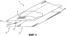
На Фиг. 1 изображен вид в перспективе полотна материала, содержащего полотна двух боковых стенок и расположенное между ними полотно нижней стенки, сложенное вдвое;In FIG. 1 shows a perspective view of a web of material containing the web of two side walls and the web of the lower wall located between them, folded in half;
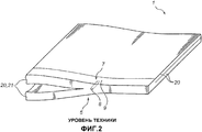
на Фиг. 2 - вид в перспективе соединения на участке полотна материала согласно Фиг. 1, при этом соединение выполнено согласно существующим прототипам;in FIG. 2 is a perspective view of a joint on a web of material according to FIG. 1, the connection is made according to existing prototypes;
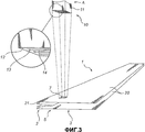
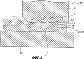
на Фиг. 3 и 4 - вид в перспективе и поперечное сечение соответственно, на которых проиллюстрирован предлагаемый способ изготовления соединения на участке полотна материала согласно Фиг. 1;in FIG. 3 and 4 are a perspective view and a cross-section, respectively, which illustrate the proposed method for manufacturing a joint on a web of material according to FIG. one;
на Фиг. 5 - вид в перспективе полотна материала с соединением на участке, выполненном согласно способу, проиллюстрированному на Фиг. 3 и 4;in FIG. 5 is a perspective view of a web of material with a connection in a portion made according to the method illustrated in FIG. 3 and 4;
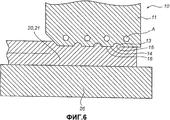
на Фиг. 6 - поперечное сечение альтернативного варианта осуществления предложенного в изобретении соединительного инструмента;in FIG. 6 is a cross-sectional view of an alternative embodiment of a connecting tool of the invention;
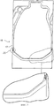
на Фиг. 7 - вид сверху дополнительного варианта осуществления соединительного инструмента согласно настоящему изобретению;in FIG. 7 is a top view of a further embodiment of a connecting tool according to the present invention;
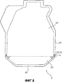
на Фиг. 8 - вид сверху заготовки контейнера.in FIG. 8 is a plan view of a container blank.
Описание вариантов осуществленияDescription of Embodiments
На Фиг. 1 представлено полотно 1 материала, содержащее первую удлиненную секцию 2, включающую в себя четыре слоя материала, и вторую удлиненную секцию 3, включающую в себя два слоя материала, при этом два из упомянутых слоев материала входят в состав первой секции 2 и второй секции 3. В варианте, представленном на Фиг. 1, слои материала состоят из двух расположенных одно против другого и параллельных полотен 20 боковых стенок и расположенного между ними полотна 21 нижней стенки, сложенного вдвое, причем полотно 1 материала содержит в поперечном направлении переход 5 от первой удлиненной секции 2, содержащей упомянутые полотна 20 двух боковых стенок и упомянутое полотно 21 нижней стенки, ко второй удлиненной секции, содержащей только упомянутые полотна 20 боковых стенок.In FIG. 1, a web of
В представленном варианте исполнения число слоев материала, таким образом, изменяется с двух до четырех в переходе 5.In the presented embodiment, the number of layers of material, thus, changes from two to four in
При обычном изготовлении, например, заготовки контейнера из полотна 1 материала такого типа, который показан на Фиг. 1, могут возникнуть сложности при выполнении надежного соединения 9 на участке 7 в области, пересекающей упомянутый переход 5.In conventional manufacturing, for example, a container blank of a
Этот сложный участок представлен на Фиг. 2. Указанная сложность проявляется в образовании сквозного канала 8, который проходит в поперечном направлении к соединению 9 параллельно переходу 5. По очевидным причинам наличие такого канала 8 делает при изготовлении заготовок контейнеров заготовку контейнера непригодной.This complex portion is shown in FIG. 2. The indicated complexity is manifested in the formation of a through
Причина формирования упомянутого сквозного канала 8 заключается в том, что соединительный инструмент (не показан), который прикладывают к полотну 1 материала на участке 7, пересекающем упомянутый переход 5, соприкасается с полотном 1 материала неравномерной толщины. Как упомянуто выше, формирование канала 8 можно исключить путем приложения достаточно большого давления, вследствие чего могут возникнуть другие проблемы, выражающиеся в создании напряжений в полотне 1 материала в форме растяжения и/или изгиба, которые могут в результате привести к разрушению.The reason for the formation of said through
На Фиг. 3 и 4 представлен соединительный инструмент 10 устройства (не показано) для выполнения соединения 9 на участке 7 полотна 1 материала.In FIG. 3 and 4, a connecting
Устройство может быть введено в состав, например, сварочной станции в машине для изготовления заготовок контейнеров.The device can be incorporated into, for example, a welding station in a machine for manufacturing container blanks.
Соединительный инструмент содержит корпус 11 с нижней сопрягаемой поверхностью 12. Множество параллельных углублений 13, имеющих треугольную форму в поперечном сечении, сформировано в упомянутой сопрягаемой поверхности 12. Углубления 13 могут также иметь, например, чашеобразную форму в поперечном сечении, показанную на Фиг. 6. Углубления 13 расположены таким образом, что сопрягаемая поверхность 12 между упомянутыми углублениями 13 содержит промежуточные плоские по существу поверхности 14.The connecting tool comprises a
В показанном варианте исполнения соединительный инструмент 10 также содержит сварочные средства, обозначенные позицией А, выполненные в виде нагревательных средств. Однако следует иметь в виду, что сварочные средства могут быть в форме средств для индукционной сварки, ультразвуковой сварки и тому подобного.In the shown embodiment, the connecting
Следует, однако, отметить, что упомянутые нагревательные средства, средства для индукционной сварки, ультразвуковой сварки могут быть расположены где-то еще в предложенном в изобретении устройстве, например в опоре 26, расположенной под соединительным инструментом 10, как показано на Фиг. 4 и 6.However, it should be noted that the said heating means, means for induction welding, ultrasonic welding can be located somewhere else in the device proposed in the invention, for example, in a
Упомянутый соединительный инструмент 10 установлен в упомянутом устройстве с возможностью перемещения по направлению к опоре 26, при котором упомянутую сопрягаемую поверхность 12 вводят в контакт с полотном 1 материала, расположенного между упомянутым сварочным инструментом 10 и упомянутой опорой 26, и выводят из контакта.Said connecting
Способ выполнения соединения 9 на участке 7 полотна 1 материала схематически проиллюстрирован на Фиг. 3 и 4.A method for making the joint 9 in the
Полотно 1 материала такого типа, которое описано выше со ссылкой на Фиг. 1, располагают таким образом между соединительным инструментом 10 и опорой 26, чтобы соединительный инструмент 10 находился непосредственно над участком 7 полотна 1 материала, при этом участок 7 имеет протяженность, при которой он пересекает переход 5 полотна 1 материала от первой секции 2 ко второй секции 3. Соединительный инструмент 10 ориентируют таким образом, чтобы его углубления 13 имели протяженность, при которой они пересекают упомянутый переход 5.The
Затем соединительный инструмент 10 перемещают по направлению к полотну 1 материала и расположенной под ним опоре 26 для введения поверхности 12 инструмента 10 в контакт с полотном 1 материала, что особенно четко показано на Фиг. 4.Then, the connecting
Под действием давления, с которым поверхность 12 соединительного инструмента 10 прикладывают к участку 7 полотна 1 материала, и тепла, генерируемого посредством упомянутого нагревательного средства, материал, расположенный на упомянутом участке 7, расплавляется в требуемой степени, в результате чего противоположные поверхности слоев материала полотна 1 материала могут быть соединены друг с другом. Каждый слой материала может состоять из ламинированного материала с расплавляемым слоем, расположенным на внутренней поверхности, с температурой плавления, которая ниже температуры плавления других слоев ламинированного материала. В результате этого обеспечивают условия, при которых только поверхности, предназначенные к соединению, действительно соединяются друг с другом.Under the action of the pressure with which the
Воздействие промежуточных поверхностей 14 поверхности 12 в процессе сварки вызывает перемещение расплавленного материала в пространство, ограниченное упомянутыми углублениями 13, с формированием таким образом выступов 15 на упомянутом участке 7 с промежуточными углублениями 16, сформированными промежуточными поверхностями 14 поверхности 12.The impact of the
Эти выступы 15 и углубления 16 имеют такую же протяженность, что и углубления 13 и промежуточные поверхности 14 инструмента 10, и, таким образом, имеют протяженность, при которой пересекают упомянутый переход 5 полотна 1 материала от первой секции 2 ко второй секции 3. Это показано более четко на Фиг. 5, на которой соединение 9 показано включенным в соединительную часть, вдоль которой полотна 20 боковых стенок и полотно 21 нижней стенки из полотна 1 материала соединены друг с другом.These
Посредством выступов 15 и углублений 16, проходящих в поперечном направлении к упомянутому переходу 5 и формируемых даже при средних давлениях, предотвращают появление показанного на Фиг. 2 сквозного канала 8 в соединении 9. Этого достигают благодаря тому, что их либо прерывают и таким образом препятствуют возможности образования канала 8 или, кроме того, полностью предотвращают появление такого канала.By means of
Таким образом, создано устройство, с помощью которого можно выполнять соединение 9, в котором нет сквозного канала 8, проходящего параллельно переходу 5, и в то же время подвергать слои полотна 1 материала щадящей обработке. Устройство также обладает преимуществом, заключающимся в точности при последующей штамповке или вырубке и точности давления, которое не должно быть столь же высоким, как в существующих прототипах.Thus, a device has been created with which you can make a
Следует принять во внимание то, что настоящее изобретение не ограничено представленными вариантами исполнения.It should be appreciated that the present invention is not limited to the embodiments presented.
Например, можно поверхность 12 соединительного инструмента 10 включить в виде секции 25 в профиль 17 инструмента 18, показанного на Фиг. 7 и введенного в устройство для изготовления заготовки контейнера в соответствии с заготовкой, показанной на Фиг. 8.For example, the
В показанном варианте исполнения подготавливают инструмент 18 устройства для изготовления заготовки 6 контейнера, изображенной на Фиг. 8, из продолговатого полотна 1 материала, показанного на Фиг. 1 и содержащего слои материала в виде двух противоположных и параллельных полотен 20 боковых стенок и расположенное между ними полотно 21 нижней стенки, сложенной вдвое, при этом упомянутое полотно 1 материала содержит в поперечном направлении переход 5 от структуры первого слоя, содержащего упомянутые полотна 20 двух боковых стенок и упомянутое полотно 21 нижней стенки, к структуре второго слоя, просто содержащей упомянутые полотна 20 боковых стенок.In the embodiment shown, a
Заготовка 6 контейнера, выполненная из упомянутого полотна 1 материала, может содержать две противоположные боковые стенки 22 и нижнюю стенку 23, сложенную вдвое, при этом в заготовке 6 контейнера выполняют ее боковые стенки 22 из соответствующих полотен 20 боковых стенок, а ее нижнюю стенку 23 из полотна 21 нижней стенки. Стенки взаимно соединяют вдоль соединительной части 24.The
Для изготовления заготовки 6 контейнера профиль 17 инструмента 18, таким образом, прикладывают к полотну 1 материала для соединения противоположных поверхностей полотен 20, 21 стенок из полотна 1 материала вдоль упомянутой соединительной части 24.For the manufacture of the
Посредством каждой секции 25 профиля 17, предназначенной для выполнения соединения 9 на участке 7 соединительной части 24, где участок 7 имеет протяженность, при которой он пересекает переход 7 упомянутого типа в полотне 1 материала, формируют сопрягаемую поверхность 12 в соответствии с описанной выше технологией со ссылкой на соединительный инструмент 10, показанный на Фиг. 3.By means of each
Таким образом, можно изготавливать заготовки 6 контейнеров с надежным соединением частей 24 также на участках 7, имеющих протяженность, при которой они пересекают переход 5 упомянутого типа. В частности, на таком участке 7 формируют выступы 15 и углубления 16, при этом с помощью упомянутых выступов 15 и углублений 16 предотвращают появление сквозных каналов 8, при образовании которых в противном случае внутреннее пространство заготовок 6 контейнеров оказывается сообщенным с окружающим пространством.Thus, it is possible to produce
Следует дополнительно принять во внимание то, что настоящее изобретение не ограничено представленными вариантами исполнения.It should further be taken into account that the present invention is not limited to the presented embodiments.
Таким образом, можно создать предложенное в изобретении устройство так, чтобы в профиле его соединительного инструмента отсутствовала секция с углублениями, которые вместо этого могут быть сформированы в опоре, к которой прикладывают соединительный инструмент с полотном материала, расположенным между ними.Thus, it is possible to create the device proposed in the invention so that in the profile of its connecting tool there is no section with recesses, which instead can be formed in a support to which a connecting tool is applied with a web of material located between them.
Можно также создать опору в таком виде, чтобы она соответствовала виду сварочного инструмента, представленного на Фиг. 3, 4 и 6, где два профиля с секциями описанного типа сводят вместе с полотном материала, расположенным между ними.You can also create a support in such a way that it matches the type of welding tool shown in FIG. 3, 4 and 6, where two profiles with sections of the described type are brought together with a web of material located between them.
Соединительный инструмент предложенного в изобретении устройства может быть выполнен таким образом, чтобы его можно было сопрягать с полотном материала при одновременном перемещении с ним для обеспечения возможности непрерывного изготовления заготовок контейнеров. Можно также выполнить соединительный инструмент для стационарного сопряжения с полотном материала, посредством чего заготовки контейнеров можно изготавливать в периодическом режиме.The connecting tool of the device of the invention can be made in such a way that it can be mated with a web of material while moving with it to enable continuous production of container blanks. You can also perform a connecting tool for stationary pairing with a web of material, whereby the container blanks can be produced in a batch mode.
Несколько модификаций и вариаций, таким образом, являются осуществимыми, что означает, что объем защиты настоящего изобретения определяется исключительно прилагаемой формулой изобретения.Several modifications and variations are thus practicable, which means that the scope of protection of the present invention is determined solely by the appended claims.
Claims (15)
упомянутое полотно (1) материала содержит первую удлиненную секцию (2) с первым числом слоев (20, 21) материала и вторую удлиненную секцию (3) со вторым числом слоев (20) материала, и при этом, по меньшей мере, один из упомянутых слоев (20) материала включен в обе первую (2) и вторую (3) секции;
упомянутый участок (7) имеет протяженность, при которой он пересекает переход (5) от первой секции (2) ко второй секции (3) полотна (1) материала,
причем способ включает стадию соединения, на упомянутом участке (7), противоположных поверхностей слоев (20, 21) материала полотна (1) материала друг с другом,
отличающийся тем, что
упомянутый участок полотна (1) материала располагают между опорой (26) и соединительным инструментом (10), при этом, по меньшей мере, один из элементов, опора или соединительный инструмент, содержит углубления (13);
сводят вместе упомянутую опору (26) и упомянутый соединительный инструмент (10) для формирования выступов (15) и углублений (16) посредством перемещения материала на упомянутом участке (7) в упомянутые углубления (13); и
ориентируют упомянутые выступы (15) и углубления (16) таким образом, чтобы они имели протяженность, при которой они пересекают упомянутый переход (7).1. The method of performing the compound (9) on the plot (7) of the canvas (1) of a material from a plastic material, wherein
said material web (1) comprises a first elongated section (2) with a first number of layers (20, 21) of material and a second elongated section (3) with a second number of layers (20) of material, and at least one of said layers (20) of material included in both the first (2) and second (3) sections;
said section (7) has a length at which it intersects the transition (5) from the first section (2) to the second section (3) of the web (1) of material,
moreover, the method includes the step of connecting, on the said section (7), opposite surfaces of the layers (20, 21) of the material of the web (1) of the material with each other,
characterized in that
said section of the web (1) of material is placed between the support (26) and the connecting tool (10), while at least one of the elements, the support or the connecting tool, contains recesses (13);
bringing together said support (26) and said connecting tool (10) for forming protrusions (15) and recesses (16) by moving material in said section (7) to said recesses (13); and
orient the said protrusions (15) and the recesses (16) so that they have a length at which they intersect the transition (7).
участок (7) имеет протяженность, при которой он пересекает переход (5) полотна (1) материала;
полотно (1) материала содержит первое число слоев (20, 21) материала на первой стороне перехода (5) и второе число слоев (20) материала на второй стороне перехода (5);
содержащее соединительный инструмент (10) с секцией (25) и опору (26), выполненные с возможностью контактирования с упомянутым участком (7) полотна материала для соединения противоположных поверхностей слоев (20, 21) материала полотна (1) материала,
отличающееся тем, что,
по меньшей мере, секция (25) соединительного инструмента (10) или опоры (26) содержит, по меньшей мере, одно углубление (13), которое предназначено для того, чтобы при сопряжении секции (25) и опоры (26) с упомянутым участком (7) обеспечивалось перемещение материала в упомянутые углубления (13), с образованием выступа с протяженностью, при которой он пересекает упомянутый переход (5).10. A device for forming a connection in the area (7) of the web (1) of a material of plastic material, while
section (7) has a length at which it crosses the transition (5) of the web (1) of the material;
the material web (1) comprises a first number of layers (20, 21) of material on the first side of the transition (5) and a second number of layers (20) of material on the second side of the transition (5);
comprising a connecting tool (10) with a section (25) and a support (26), made with the possibility of contacting with the aforementioned section (7) of the material web to connect the opposite surfaces of the layers (20, 21) of the material of the web (1) of the material,
characterized in that,
at least the section (25) of the connecting tool (10) or support (26) contains at least one recess (13), which is designed so that when pairing the section (25) and the support (26) with said section (7) the material was transported into the said recesses (13), with the formation of a protrusion with a length at which it intersects the transition (5).
Applications Claiming Priority (2)
| Application Number | Priority Date | Filing Date | Title |
|---|---|---|---|
| SE0401463-5 | 2004-06-09 | ||
| SE0401463A SE528141C2 (en) | 2004-06-09 | 2004-06-09 | Method and apparatus for providing sealing and use of such a method |
Publications (2)
| Publication Number | Publication Date |
|---|---|
| RU2006147011A RU2006147011A (en) | 2008-07-20 |
| RU2376142C2 true RU2376142C2 (en) | 2009-12-20 |
Family
ID=32653558
Family Applications (1)
| Application Number | Title | Priority Date | Filing Date |
|---|---|---|---|
| RU2006147011A RU2376142C2 (en) | 2004-06-09 | 2005-06-03 | Method and device for forming tight connection and use of above method |
Country Status (11)
| Country | Link |
|---|---|
| US (1) | US7731645B2 (en) |
| EP (1) | EP1753603B1 (en) |
| CN (1) | CN101098780B (en) |
| AT (1) | ATE439233T1 (en) |
| DE (1) | DE602005015958D1 (en) |
| ES (1) | ES2330764T3 (en) |
| HK (1) | HK1116137A1 (en) |
| RU (1) | RU2376142C2 (en) |
| SE (1) | SE528141C2 (en) |
| UA (1) | UA89786C2 (en) |
| WO (1) | WO2005120820A1 (en) |
Families Citing this family (3)
| Publication number | Priority date | Publication date | Assignee | Title |
|---|---|---|---|---|
| PL2871051T3 (en) | 2013-11-07 | 2018-06-29 | Ecolean Ab | Device and method for attachment of an opening device on a flexible package |
| WO2015111736A1 (en) * | 2014-01-24 | 2015-07-30 | 株式会社細川洋行 | Gusset bag, method for producing gusset bag, and method for joining laminate |
| JP7291400B2 (en) * | 2020-05-21 | 2023-06-15 | 押尾産業株式会社 | Manufacturing method of packaging bag |
Family Cites Families (17)
| Publication number | Priority date | Publication date | Assignee | Title |
|---|---|---|---|---|
| US2086735A (en) * | 1932-05-07 | 1937-07-13 | Du Pont | Joining or sealing material |
| DE1802886U (en) * | 1959-09-09 | 1959-12-24 | Hesser Ag Maschf | HEAT SEALING DEVICE. |
| SE314626B (en) * | 1965-12-09 | 1969-09-08 | Akerlund & Rausing Ab | |
| CH530856A (en) * | 1971-03-09 | 1972-11-30 | Geneco | Apparatus for closing, by means of ultrasonic welding, one end of plastic tubes |
| US4079662A (en) * | 1976-11-30 | 1978-03-21 | Triangle Package Machinery Company | Bag making machine |
| US4534818A (en) * | 1983-12-22 | 1985-08-13 | Frito-Lay, Inc. | Method and apparatus for ultrasonic sealing |
| US4582555A (en) * | 1984-12-17 | 1986-04-15 | Crown Zellerbach Corporation | Heatseal die |
| EP0256791A3 (en) * | 1986-08-18 | 1989-11-29 | Nabisco Brands, Inc. | Package for microwaveable popcorn, method for production of the package, and apparatus for sealing the package |
| JP2825880B2 (en) * | 1989-11-01 | 1998-11-18 | 株式会社東京自働機械製作所 | Horizontal sealing device for bag making, filling and packaging machines |
| US5015223A (en) * | 1989-12-06 | 1991-05-14 | Zip-Pak, Incorporated | Hotseal jaws and cutoff knife assembly for processing thermoplastic film bag making material |
| GB2267250B (en) * | 1992-05-28 | 1996-01-24 | Food Machinery Design Ltd | Heat seals |
| US5868901A (en) * | 1996-09-13 | 1999-02-09 | Lako Tool & Manufacturing, Inc. | Crimper assembly for sealing overlapping portions of a sheet of packaging material |
| JP4282179B2 (en) * | 1999-09-30 | 2009-06-17 | 四国化工機株式会社 | Ultrasonic sealing device |
| JP4603122B2 (en) * | 2000-02-23 | 2010-12-22 | 四国化工機株式会社 | Ultrasonic sealing device |
| US20020170272A1 (en) * | 2001-05-18 | 2002-11-21 | Rodney Wayne Cooper | Contoured seal facing for seal jaws in vertical form, fill, and seal packaging system |
| SE522385C2 (en) | 2001-11-14 | 2004-02-03 | Eco Lean Res & Dev As | Packaging and apparatus and method of manufacture thereof |
| US6877296B2 (en) * | 2002-07-22 | 2005-04-12 | Frito-Lay North America, Inc. | Isolated targeting of problem areas in hermetic seals |
-
2004
- 2004-06-09 SE SE0401463A patent/SE528141C2/en unknown
-
2005
- 2005-03-06 UA UAA200700167A patent/UA89786C2/en unknown
- 2005-06-03 US US11/597,375 patent/US7731645B2/en active Active
- 2005-06-03 AT AT05748779T patent/ATE439233T1/en not_active IP Right Cessation
- 2005-06-03 ES ES05748779T patent/ES2330764T3/en active Active
- 2005-06-03 WO PCT/SE2005/000845 patent/WO2005120820A1/en active Application Filing
- 2005-06-03 DE DE602005015958T patent/DE602005015958D1/en active Active
- 2005-06-03 RU RU2006147011A patent/RU2376142C2/en active
- 2005-06-03 EP EP05748779A patent/EP1753603B1/en active Active
- 2005-06-03 CN CN2005800187799A patent/CN101098780B/en active Active
-
2008
- 2008-06-18 HK HK08106733.1A patent/HK1116137A1/en unknown
Also Published As
| Publication number | Publication date |
|---|---|
| ATE439233T1 (en) | 2009-08-15 |
| SE528141C2 (en) | 2006-09-12 |
| ES2330764T3 (en) | 2009-12-15 |
| US7731645B2 (en) | 2010-06-08 |
| SE0401463D0 (en) | 2004-06-09 |
| RU2006147011A (en) | 2008-07-20 |
| EP1753603B1 (en) | 2009-08-12 |
| WO2005120820A1 (en) | 2005-12-22 |
| SE0401463L (en) | 2005-12-10 |
| EP1753603A1 (en) | 2007-02-21 |
| CN101098780B (en) | 2010-12-08 |
| DE602005015958D1 (en) | 2009-09-24 |
| US20070245693A1 (en) | 2007-10-25 |
| UA89786C2 (en) | 2010-03-10 |
| HK1116137A1 (en) | 2008-12-19 |
| CN101098780A (en) | 2008-01-02 |
Similar Documents
| Publication | Publication Date | Title |
|---|---|---|
| RU2392202C2 (en) | Facility and procedure for transverse sealing | |
| US8011568B2 (en) | Method for manufacturing a board tray, a blank for the tray, and a tray obtained by the method | |
| RU2337862C2 (en) | Device and method of welded joint preparation, and also of foil bags manufacture | |
| RU2376142C2 (en) | Method and device for forming tight connection and use of above method | |
| CN102227285B (en) | Method for producing overlapping weld joints and overlapping weld joint | |
| EP2442963A1 (en) | Ultrasonic sealing jaw and method for ultrasonic sealing | |
| US4655386A (en) | Packing container blank and container made therefrom | |
| JP4426441B2 (en) | System for sealing plastic containers | |
| US3291369A (en) | Means for scoring containers | |
| EP0979723B1 (en) | Heat-sealing apparatus | |
| EP3219629B1 (en) | A method and a machine for producing a sealed package | |
| JP2739640B2 (en) | Continuous production method of hermetically sealed package formed of laminate film | |
| US4834822A (en) | Method for joining overlapping edges of a multi-layer foil, and a tubular liner produced according to the method | |
| JP4195798B2 (en) | End treatment method for hollow resin plate and method for manufacturing case blank or box | |
| CA1225049A (en) | Joint on packing containers and a method and arrangement for the manufacture of the same | |
| JP2008222255A (en) | Box body using hollow synthetic resin plate and its manufacturing method | |
| EP0978459A1 (en) | Draw tape bag and method for its manufacture | |
| JPH09182982A (en) | Thermit welding method for rail | |
| JP2022167269A (en) | Method and apparatus for manufacturing paper food storage container | |
| KR20240018470A (en) | Membrane cartridge and membrane cartridge manufacturing method | |
| JP2021194674A (en) | Different material bonding method | |
| EP0144469A1 (en) | A joint on packing containers and a method for the manufacture of the same | |
| JPS6213172B2 (en) | ||
| JPH09122980A (en) | Casting mold for welding rails | |
| JPS59174282A (en) | Square can and its production |
Legal Events
| Date | Code | Title | Description |
|---|---|---|---|
| PD4A | Correction of name of patent owner | ||
| PC41 | Official registration of the transfer of exclusive right |
Effective date: 20140304 |