RU2369088C1 - Automated method of protection from hail hitting - Google Patents
Automated method of protection from hail hitting Download PDFInfo
- Publication number
- RU2369088C1 RU2369088C1 RU2008121898/12A RU2008121898A RU2369088C1 RU 2369088 C1 RU2369088 C1 RU 2369088C1 RU 2008121898/12 A RU2008121898/12 A RU 2008121898/12A RU 2008121898 A RU2008121898 A RU 2008121898A RU 2369088 C1 RU2369088 C1 RU 2369088C1
- Authority
- RU
- Russia
- Prior art keywords
- clouds
- hail
- reagent
- canopy
- hazard
- Prior art date
Links
Images


Landscapes
- Radar Systems Or Details Thereof (AREA)
Abstract
Description
Изобретение относится к области активных воздействий на облака с целью защиты сельскохозяйственных культур от градобитий с использованием наземных и авиационных средств засева облаков льдообразующими реагентами.The invention relates to the field of active impacts on clouds in order to protect crops from hail by using ground and aviation means of sowing clouds with ice-forming reagents.
Известно несколько способов активного воздействия на градовые облака, основанных на внесении в них кристаллизующих реагентов с помощью артиллерийских снарядов, ракет и пиропатронов, отличающихся между собой местом, температурным уровнем, дозировкой и размерами областей внесения реагента (засева кристаллизующими частицами).Several methods are known for actively affecting hail clouds, based on the introduction of crystallizing reagents into them using artillery shells, rockets and pyro cartridge, which differ in location, temperature level, dosage and size of the areas of reagent application (seeding with crystallizing particles).
Первые способы воздействия на градовые облака предусматривали внесение реагента в зону зарождения и роста града [1, 2].The first methods of influencing hail clouds included introducing a reagent into the zone of hail nucleation and growth [1, 2].
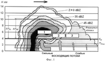
В способе [1] местом внесения реагента является зона роста града 1 (см. фиг.1), выделяемая радиолокатором, как передняя по направлению перемещения часть области повышенной радиолокационной отражаемости, в которой в зрелых градовых облаках происходит рост града. Практика показала, что такой способ не обеспечивает прерывания выпадающего града и может приводить даже к усилению интенсивности градобития за счет создания смешанной (капельно-кристаллической) среды питания градин, приводящей к ускорению роста града. Поэтому применение способа было прекращено.In the method [1], the place of introduction of the reagent is the growth zone of hail 1 (see Fig. 1), allocated by the radar, as the front part of the region of increased radar reflectivity in which the growth of hail occurs in mature hail clouds. Practice has shown that this method does not interrupt the falling hail and can even lead to an increase in the intensity of hail due to the creation of a mixed (drip-crystalline) hail feeding medium, leading to accelerated hail growth. Therefore, the application of the method was discontinued.
Второй способ [2] предусматривал внесение кристаллизующего реагента в зону зарождения и роста града 2 (см. фиг.1), расположенную перед областью повышенной радиолокационной отражаемости, в зоне восходящих потоков в слое между уровнями изотерм от -6 до -25°С. Предусматривалось создание концентрации льдообразующих частиц порядка 106 на м3, что должно было привести к повышению концентрации зародышей града в 1000 раз (по сравнению с природной) и обеспечить уменьшение размера растущего града примерно в 10 раз за счет конкуренции за облачную влагу, а образующиеся при этом мелкие градины при падении в теплом слое атмосферы успеют растаять, превращаясь в дождь. Однако и этот способ не обеспечивал прерывания града из зрелых градовых облаков, так как искусственные ледяные частицы, образовавшиеся на микроскопических частицах кристаллизующего реагента размером порядка 0,1 мкм, не могут эффективно конкурировать с зародышами, имеющими размер 5-10 мм.The second method [2] involved introducing a crystallizing reagent into the zone of nucleation and growth of hail 2 (see Fig. 1), located in front of the region of increased radar reflectivity, in the zone of upward flows in the layer between the levels of isotherms from -6 to -25 ° C. It was planned to create a concentration of ice-forming particles of the order of 10 6 per m 3 , which should lead to an increase in the concentration of hail nuclei by a factor of 1000 (compared to natural) and to provide a decrease in the size of the growing hail by about 10 times due to competition for cloudy moisture, and In this case, small gradients, when falling in a warm layer of the atmosphere, will have time to melt, turning into rain. However, this method did not provide interruption of hail from mature hail clouds, since artificial ice particles formed on microscopic particles of a crystallizing reagent of about 0.1 μm in size cannot compete effectively with nuclei having a size of 5-10 mm.
Более совершенным является известный способ прерывания града из суперячейковых облаков [3], предусматривающий воздействие на них кристаллизующим реагентом в слое -8÷-12°С путем предварительного выделения области формирования градовых зародышей 3 (см. фиг.1) как площадь прямоугольника, ограниченного шириной предфронтальной части навеса радиоэха и изолиниями радиолокационной отражаемости 35 и 15 dBZ и внесения реагента впереди по направлению перемещения области локализации града, ограниченной изолинией радиолокационной отражаемости Z=45 dBZ (см. позицию 5 на фиг.2). Этот способ не учитывал направление навеса радиоэха, в котором происходит зарождение и рост града, который формируется над областью мощного восходящего потока и, как правило, отклоняется в северном полушарии вправо от направления перемещения облака, а в южном - влево на угол до 45-90 градусов. При больших углах отклонения направления навеса радиоэха, как показала практика, воздействие было мало успешным.More perfect is the known method of interrupting hail from supercell clouds [3], which involves exposing them to a crystallizing reagent in a layer of -8 ÷ -12 ° C by preliminarily selecting the region of formation of hail nuclei 3 (see Fig. 1) as the area of a rectangle limited by the width the prefrontal part of the canopy of the radio echo and isolines of radar reflectivity of 35 and 15 dBZ and the introduction of the reagent in front in the direction of movement of the localization region of the city, limited by the isoline of radar reflectivity Z = 45 dBZ (with .
Наиболее близким по технической сущности является способ активных воздействий на градовые облака [4] путем внесения кристаллизующего реагента в область будущего градообразования 3 (см. фиг.1), ограниченную снизу пороговым уровнем температуры кристаллизующего действия реагента, а по бокам - изоконтурами пороговых уровней радиолокационной отражаемости 35 и 15 dBZ, полученными в каждом предыдущем и последующем циклах измерения, осуществляемых с периодичностью 3-5 мин, часть которой отсекается изоконтуром радиолокационной отражаемости 35 dBZ, полученным в последующем цикле измерения и расширенную во фронтальной части области будущего градообразования на 2,5 км в направлении навеса радиоэха, чтобы засеять кристаллизующими частицами фидерные облака 4 (см. фиг.1), которые своими восходящими потоками подпитывают влагой основное градовое облако [4] (ПРОТОТИП).The closest in technical essence is the method of active effects on hail clouds [4] by introducing a crystallizing reagent into the region of future city formation 3 (see Fig. 1), bounded below by the threshold temperature level of the crystallizing action of the reagent, and on the sides by isocontours of threshold levels of
Недостатком этого способа, как и предыдущего [3], является неточное выделение площади и направления навеса радиоэха, в котором расположены области будущего градообразования и области зарождения и роста града (см. фиг.1). За навес радиоэха принимается не только область радиоэха, нависающего над мощной струей восходящего потока, но и область наклона радиоэха на подветренную сторону облака под действием сильного ветра в среднем и верхнем слоях облакообразования (на высотах выше 5 км). Это приводит к значительному завышению площади навеса радиоэха, к завышенному расходу средств воздействия, внесению части реагента на подветренную сторону облака, в то время как градообразующая активность сосредоточена на наветренном фланге. Это снижает эффективность воздействия, затягивает время воздействия и приводит к пропуску градобитий на защищаемой территории. Во-вторых, этот способ, также как и все предыдущие, предусматривает создание в области засева концентрации кристаллизующих частиц порядка 105-106. Теоретические и экспериментальные исследования [6] показали, что в случаях мощных градовых облаков такой дозировки недостаточно, так как высокая турбулентность приводит к быстрому уменьшению концентрации частиц за время их действия (в первую минуту примерно в 100 раз, в последующие 2 мин в 10 раз). В итоге этой дозировки становится недостаточно для микрофизической перестройки облака и предотвращения образования града.The disadvantage of this method, as well as the previous one [3], is the inaccurate allocation of the area and direction of the canopy of the radio echo, in which there are areas of future city formation and areas of nucleation and growth of the city (see figure 1). For the canopy of the radio echo, not only the region of the radio echo hanging over a powerful jet of the upward stream is taken, but also the region of the inclination of the radio echo to the leeward side of the cloud under the influence of strong wind in the middle and upper layers of cloud formation (at altitudes above 5 km). This leads to a significant overestimation of the area of the canopy of the radio echo, to the overestimated consumption of the means of exposure, the introduction of part of the reagent on the leeward side of the cloud, while the city-forming activity is concentrated on the windward flank. This reduces the effectiveness of the impact, prolongs the exposure time and leads to the passage of hail in the protected area. Secondly, this method, as well as all the previous ones, provides for the creation of a concentration of crystallizing particles of the order of 10 5 -10 6 in the seed area. Theoretical and experimental studies [6] showed that in cases of powerful hail clouds such a dosage is not enough, since high turbulence leads to a rapid decrease in the concentration of particles during their action (about 100 times in the first minute, 10 times in the next 2 minutes) . As a result, this dosage becomes insufficient for the microphysical restructuring of the cloud and to prevent the formation of hail.
Кроме того, используемые в рассмотренных способах критерии распознавания градовых, градоопасных и потенциально-градоопасных облаков [5] приводят к завышению числа засеваемых облаков, неточному определению начала и прекращения воздействия и, следовательно, к излишнему расходу средств воздействия. Таким образом, ни один из известных способов не обеспечивает четкого распознавания объектов воздействия, не содержит универсального способа выделения места внесения реагента в градовых облаках разных типов (одноячейковых, упорядоченных и неупорядоченных многоячейковых, гибридных, суперячейковых), имеющих различное пространственное строение, левостороннее и правостороннее развитие, различное расположение областей зарождения и роста града.In addition, the criteria used for the recognition of hail, hail and potentially hazardous clouds [5] used in the methods considered above lead to an overestimation of the number of cloudy clouds, inaccurate determination of the onset and termination of exposure, and, consequently, excessive expenditure of exposure means. Thus, none of the known methods provides a clear recognition of the objects of influence, does not contain a universal way to identify the place of application of the reagent in hail clouds of different types (single-cell, ordered and disordered multi-cell, hybrid, super-cell) with different spatial structures, left-side and right-side development , a different arrangement of the areas of origin and growth of hail.
Техническим результатом от использования заявленного способа является повышение эффективности защиты от градобитий и сокращение расхода средств воздействия (противоградовых ракет, снарядов и пиропатронов, снаряженных кристаллизующими реагентами).The technical result from the use of the claimed method is to increase the efficiency of protection against hail and reduce the cost of exposure (anti-hail rockets, shells and pyro cartridge equipped with crystallizing reagents).
Технический результат достигается тем, что в известном способе активных воздействий на градовые облака, включающем радиолокационное зондирование облаков, последующее определение типа градовых облаков, определение градоопасности облаков, выделение в облаках областей будущего градообразования и внесение в эти области реагента с помощью применяемых средств воздействия, для повышения точности распознавания категорий градоопасности облаков и их конвективных ячеек известные критерии, основанные на измерении одномерных параметров облаков, дополнены новыми критериями, основанными на измерении двумерных и трехмерных параметров, более адекватно характеризующих степень градоопасности облаков, а для повышения эффективности воздействия на облака различной градоопасности уточнено место внесения и дозировка реагента (средств воздействия).The technical result is achieved by the fact that in the known method of active actions on hail clouds, including radar sounding of clouds, subsequent determination of the type of hail clouds, determination of the hail hazard of the clouds, highlighting areas of future hail formation in the clouds and introducing a reagent into these areas using the applied means of exposure, to increase recognition accuracy of hail hazard categories of clouds and their convective cells; known criteria based on the measurement of one-dimensional cloud parameters s, supplemented with new criteria based on the measurement of two-dimensional and three-dimensional parameters characterizing the degree of more adequately hail clouds and to increase the efficiency of exposure to various clouds hail precised place of application and reagent dosage (exposure means).
Наиболее часто на практике применяется одноволновый способ распознавания категорий градоопасности облаков по критериальным значениям (см. таблицу) максимальной радиолокационной отражаемости на длине волны 10 см (Zmax в dBZ) и превышение высоты максимума радиоэха (ΔHZmax в км) или верхней границы области повышенного радиоэха (ΔН35 и ΔН45 в км) над уровнем изотермы 0°С [5].Most often, in practice, a single-wave method is used to recognize cloud hail categories by criteria (see table) of maximum radar reflectivity at a wavelength of 10 cm (Z max in dBZ) and exceeding the height of the maximum radio echo (ΔH Zmax in km) or the upper boundary of the region of increased radio echo (ΔН 35 and ΔН 45 in km) above the level of the
Однако эти параметры, измеряемые в точке максимума радиолокационной отражаемости и в точке максимальной высоты верхней границы области повышенного радиоэха, зачастую неадекватно отображают степень градоопасности облаков, которые, как известно, имеют трехмерную структуру, поэтому число градоопасных облаков значительно завышается (в 2-3 раза) и ведет к излишнему расходу средств воздействия. Поэтому предлагается дополнить применяемые критерии распознавания категорий градоопасности облаков новыми критериями, основанными на измерении двумерных и трехмерных параметров облаков, которые стало возможным измерять с развитием автоматизированных систем обработки радиолокационной информации, обеспечивающих качественно новые возможности повышения точности распознавания. Экспериментальные исследования показали, что наиболее информативными являются такие параметры, как:However, these parameters, measured at the point of maximum radar reflectivity and at the point of maximum height of the upper boundary of the region of increased radio echo, often inadequately reflect the degree of hail hazard of the clouds, which are known to have a three-dimensional structure, so the number of hail hazardous clouds is significantly overestimated (2-3 times) and leads to excessive consumption of means of influence. Therefore, it is proposed to supplement the applicable criteria for recognizing cloud hail categories with new criteria based on the measurement of two-dimensional and three-dimensional cloud parameters, which has become possible to measure with the development of automated systems for processing radar information, providing qualitatively new possibilities for increasing recognition accuracy. Experimental studies have shown that the most informative are parameters such as:
а) приведенная (интегрированная по высоте) водность Δq (кг/м2) переохлажденного слоя облака выше изотермы 0°С, где происходит зарождение и рост града;a) reduced (integrated over height) water content Δq (kg / m 2 ) of the supercooled cloud layer above the 0 ° C isotherm, where hail nucleation and growth occur;
б) отношение интегральной водности объемов облака выше и ниже изотермы 0°С (↑ΔМZi/↓ΔMZi), ограниченных изолинией отражаемости Zi, характеризующее отношение водосодержания слоев роста и таяния града.b) the ratio of the integral water content of the cloud volumes above and below the 0 ° C isotherm (↑ ΔM Zi / ↓ ΔM Zi ), limited by the reflectivity line Zi, which characterizes the ratio of the water content of the growth and melting layers of the hail.
Измерение этих параметров осуществляется путем обзора трехмерного пространства с периодичностью 3 мин, аналого-цифрового преобразования, осреднения и ввода радиолокационных сигналов в компьютер по 360 дискретным значениям азимута и 400 ячейкам дальности протяженностью 0,5 км, расчета суммарного содержания воды в единице объема в каплях дождя qR и градинах qH (г/м3) в n-й ячейке облачного объема по формуле:Measurement of these parameters is carried out by reviewing three-dimensional space with a frequency of 3 min, analog-to-digital conversion, averaging and entering radar signals into a computer using 360 discrete azimuth values and 400 cells of a range of 0.5 km in length, calculating the total water content per unit volume in rain drops q R and hail q H (g / m 3 ) in the n-th cloud volume cell according to the formula:
где Z10n - радиолокационная отражаемость на длине волны λ=10 см в n-й ячейке площади радиолокационного обзора; и qRn и qHn - содержание воды в г/м3 в виде дождя и града соответственно в n-й ячейке площади обзора; k - параметр, зависящий от соотношения дождевой и градовой воды, для которого эмпирически получено выражение: k=0,0285Z10n-1,14.where Z 10n is the radar reflectivity at a wavelength of λ = 10 cm in the n-th cell of the area of the radar survey; and q Rn and q Hn are the water content in g / m 3 in the form of rain and hail, respectively, in the nth cell of the viewing area; k is a parameter depending on the ratio of rain and city water, for which the expression is empirically obtained: k = 0.0285Z 10n -1.14.
Суммирование по формуле (2) значения qn по всей толще облачного слоя выше изотерм 0°С, позволяет получить вертикально интегрированное содержание воды в слое зарождения и роста града ↑Δq, которую обычно называют приведенной (к основанию) водностью:The summation by formula (2) of the values of q n over the entire thickness of the cloud layer above the
![]()
![]()
где ↑qmi - водность единичного объема облака в m-й ячейке площади горизонтального сечения облака на i-й высоте; ΔHi - вертикальная протяженность i-го слоя облака, равная 0,5 км.where ↑ q mi is the water content of a unit cloud volume in the mth cell of the horizontal sectional area of the cloud at the i-th height; ΔH i is the vertical extent of the i-th layer of the cloud, equal to 0.5 km.
Расчет соотношения интегрального водосодержания переохлажденной (↑ΔMZi) и теплой (↓ΔMZi) частей облака осуществляется путем интегрирования приведенной водности Δq по всей площади горизонтального сечения облака указанных слоев по формуле:The calculation of the ratio of the integral water content of the supercooled (↑ ΔM Zi ) and warm (↓ ΔM Zi ) parts of the cloud is carried out by integrating the reduced water content Δq over the entire horizontal section of the cloud of the indicated layers by the formula:
где ↑Δqm(Zi) и ↓Δqm(Zi) - значения приведенной водности переохлажденной и теплой частей облака в m-й ячейке площади облака, внутри изоконтура с отражаемостью Zi=25 или 35 dBZ; Sm(Zi) - площадь m-й ячейки площади облака внутри изоконтура с заданным значением Zi.where ↑ Δq m (Z i ) and ↓ Δq m (Z i ) are the reduced water content of the supercooled and warm parts of the cloud in the mth cell of the cloud area, inside the isocontour with reflectivity Z i = 25 or 35 dBZ; S m (Z i ) is the area of the mth cell of the cloud area inside the isocontour with a given value of Z i .
Отличительным признаком является то, что расчет ↑ΔMZi/↓ΔMZi осуществляется только по той части облака, где отношение приведенной водности переохлажденного и теплого слоев облака ↑Δq25/↓Δq25>1. Это дополнительное условие обеспечивает выделение области навеса радиоэха, диагноз наличия условий для зарождения и роста града и оценку возможности перерастания более низкой категории градоопасности в более высокую, отсекая облака не имеющие навеса радиоэха и, следовательно, не имеющие мощных восходящих потоков, индикатором которых является наличие навеса радиоэха.A distinctive feature is that the calculation ↑ ΔM Zi / ↓ ΔM Zi is carried out only for that part of the cloud where the ratio of the reduced water content of the supercooled and warm layers of the cloud is ↑ Δq 25 / ↓ Δq 25 > 1. This additional condition provides the identification of the area of the echo canopy, the diagnosis of the conditions for the emergence and growth of the hail, and the assessment of the possibility of the development of a lower category of urban hazard into a higher one, cutting off clouds that do not have a canopy of radio echo and, therefore, do not have powerful upward flows, the indicator of which is the canopy radio echo.
Расчеты значений ↑Δq и ↑ΔMZi/↓ΔMZi, а также распознавание категорий градоопасности облаков автоматизированы и позволяют оперативно отобразить на дисплее карту категорий градоопасности всех облаков в радиусе радиолокационного обзора, таблицу параметров любого выбранного облака с указанием его категории градоопасности и обеспечивают удобство оперативного применения предлагаемого способа.Calculations of the values ↑ Δq and ↑ ΔM Zi / ↓ ΔM Zi , as well as recognition of cloud hazard categories of clouds, are automated and allow you to quickly display on the display a map of the categories of hail hazard of all clouds in the radius of the radar view, a table of parameters of any selected cloud indicating its urban hazard category and provide operational convenience application of the proposed method.
Комплекс критериев распознавания категорий градоопасности облаков представлены в таблице. Этот комплекс критериев включает в себя и ряд известных критериев (действующих в настоящее время на практике противоградовой защиты [5]), но скорректированных с учетом опыта многолетнего использования.A set of criteria for recognizing categories of hail hazard clouds are presented in the table. This set of criteria includes a number of well-known criteria (currently operating in practice of anti-hail protection [5]), but adjusted taking into account the experience of many years of use.
![]()
![]()
![]()
![]()
![]()
![]()

После распознавания категорий градоопасности облаков по предлагаемому автоматизированному способу защиты от градобитий осуществляется выделение областей будущего градообразования для внесения реагента.After recognizing the categories of hail hazard of the clouds by the proposed automated method of protection from hail, areas of future hail formation are introduced for introducing the reagent.
В градовых и сверхмощных градовых облаках с параметрами, соответствующими критериям III и IV категории градоопасности, область будущего градообразования выделяют в слое от 1,0 до 5 км над уровнем изотермы 0°С как фронтальную часть нависающего радиоэха и окружающие ее фидерные облака. Реагент вводится по всей площади горизонтального сечения области будущего градообразования (см. фиг.2, с), ограниченной:In hailstones and heavy hailstones with parameters meeting the criteria of hazard category III and IV, the area of future hail formation is distinguished in the layer from 1.0 to 5 km above the 0 ° C isotherm as the front part of the overhanging radio echo and surrounding feeder clouds. The reagent is introduced over the entire horizontal section of the area of future city formation (see figure 2, c), limited:
- с тыльной стороны изолинией отражаемости Z=35 dBZ;- on the back side, the reflectivity isoline Z = 35 dBZ;
- с фронтальной стороны изолинией Z=0 dBZ, расширенной по направлению навеса радиоэха на 3-4 км;- on the front side, the isoline Z = 0 dBZ, expanded in the direction of the canopy of the radio echo by 3-4 km;
- с наветренной стороны изолинией Z=0 dBZ, расширенной на 3-4 км навстречу вектору ведущего потока, проведенному по тыловой границе навеса радиоэха;- on the windward side, the isoline Z = 0 dBZ, extended by 3-4 km to meet the leading flow vector drawn along the rear border of the radio echo canopy;
- с подветренной стороны линией, проходящей параллельно навесу радиоэха по касательной к изолинии Z=55 dBZ, отсекающей область «ложного» навеса радиоэха, которая расположена на подветренном фланге, где начинается расширение радиоэха с Z=0-45 dBZ.- on the leeward side, a line running parallel to the canopy of the radio echo tangential to the isoline Z = 55 dBZ, cutting off the area of the “false” canopy of the radio echo, which is located on the leeward flank, where the expansion of the radio echo begins with Z = 0-45 dBZ.
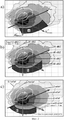
Важнейшим фактором, определяющим успех в предотвращении града, является точное выделение навеса радиоэха и его направления. Направление навеса радиоэха известным способом [3-5] определяют по двухуровневому сечению, как линию, соединяющую центры изолинии Z=45 dBZ на высоте максимального сдвига этой изолинии относительно такой же изолинии в зоне осадков (на высоте около 1,5-2 км над уровнем расположения радиолокатора).The most important factor determining success in preventing hail is the precise allocation of the canopy of the radio echo and its direction. The direction of the canopy of the radio echo in a known manner [3-5] is determined by a two-level cross-section, as a line connecting the centers of the contour Z = 45 dBZ at the height of the maximum shift of this contour relative to the same contour in the precipitation zone (at an altitude of about 1.5-2 km above the level radar location).
В отличие от этого в предлагаемом способе вместо этих визуально определяемых точек используются координаты точек центров масс переохлажденной и теплой частей облака, более адекватно рассчитываемых вычислителем системы автоматизации технологических процессов «АСУ-МРЛ». Следует также отметить, что навес радиоэха на разных высотах может выступать относительно зоны осадков в разной степени. Чтобы исключить операцию поиска высоты максимального выступа навеса радиоэха и повысить оперативность выделения всей области навеса радиоэха, предусмотрено автоматическое построение карты двухуровневого сечения облаков (см. рис.2 и 3), на которой в цветовой палитре отображается:In contrast to this, in the proposed method, instead of these visually determined points, the coordinates of the points of the centers of mass of the supercooled and warm parts of the cloud, more adequately calculated by the computer of the automation system of technological processes "ASU-MRL", are used. It should also be noted that the canopy of the radio echo at different heights can protrude relative to the zone of precipitation to varying degrees. In order to exclude the operation of searching for the height of the maximum protrusion of the echo canopy and increase the efficiency of highlighting the entire area of the echo canopy, it is possible to automatically construct a map of a two-level section of clouds (see Fig. 2 and 3), which displays in the color palette:
- карта изолиний приведенной водности Δq переохлажденного слоя облака от 1 до 5 км над уровнем изотермы 0°С, где обычно располагается навес радиоэха;- a map of isolines of reduced water content Δq of a supercooled cloud layer from 1 to 5 km above the 0 ° C isotherm, where the radio echo canopy is usually located;
- а также контуры Z=45 и 55 dBZ в слое осадков (другим цветом).- as well as the contours of Z = 45 and 55 dBZ in the precipitation layer (in a different color).
В облака IV категории градоопасности реагент вводится четырехкратно с интервалом 3-4 мин, а в облака III категории градоопасности - трехкратно.In reagent category IV clouds, the reagent is introduced four times with an interval of 3-4 minutes, and three times in the clouds of city hazard category III.
В градоопасных облаках (или их конвективных ячейках) с параметрами соответствующими критериям II категории градоопасности область будущего градообразования выделяют как область нависающего радиоэха, расположенную во фронтальной части облака в слое от 1,0 до 5 км над уровнем изотермы 0°С, ограниченная с тыльной стороны изолинией Z=35 dBZ, с фронтальной изолинией Z=0 dBZ, а с наветренной и подветренной сторон шириной навеса радиоэха. Реагент вносят по всей площади этой области с охватом наветренного фланга (см. фиг.3) двукратно с интервалом 6 мин в 1 км слой облака с температурой от -3 до -9°С. В случае более высокого расположения навеса радиоэха реагент вносится в 1 км слой над уровнем нижней границы навеса радиоэха.In hail clouds (or their convective cells) with parameters corresponding to the criteria of hail hazard category II, the area of future hail formation is identified as a region of overhanging radio echo located in the front of the cloud in a layer from 1.0 to 5 km above the 0 ° C isotherm, limited from the back the contour Z = 35 dBZ, with the front contour Z = 0 dBZ, and on the windward and leeward sides the width of the canopy of the radio echo. The reagent is introduced over the entire area of this region with the coverage of the windward flank (see Fig. 3) twice with an interval of 6 min in 1 km, a cloud layer with a temperature of from -3 to -9 ° C. In the case of a higher location of the echo canopy, the reagent is introduced in a 1 km layer above the lower boundary of the echo canopy.
В потенциально-градоопасных облаках (или их новых конвективных ячейках), имеющих параметры, соответствующие критериям I категории градоопасности, область будущего градообразования выделяется как область первого радиоэха, зародившегося в слое от 0 до 5 км над уровнем изотермы 0°С, и ограниченная изолинией Z=0 dBZ. Реагент при этом вносится однократно в 1 км слой облака, расположенный над уровнем нижней границы нависающего радиоэха, по всей площади радиоэха с Z≥10 dBZ (см. фиг.4).In potentially hail-hazardous clouds (or their new convective cells) having parameters that meet the criteria of hail hazard category I, the region of future hail formation is identified as the region of the first radio echo originating in the layer from 0 to 5 km above the 0 ° C isotherm, and limited by the isoline Z = 0 dBZ. In this case, the reagent is introduced once in a 1 km cloud layer located above the lower boundary of the overhanging radio echo over the entire area of the radio echo with Z≥10 dBZ (see Fig. 4).
Наиболее эффективным по данным теоретического моделирования и многолетнего опыта противоградовой защиты в разных регионах является внесение реагента в 1 км слой облака между изотермами -3 и -9°С, где расположен первый максимум роста, размножения и агрегации кристаллов, максимум естественного размножения кристаллов, а также порог кристаллизующего действия применяемых реагентов. Но в случаях высокого расположения навеса радиоэха (или первого радиоэха новых конвективных ячеек) реагент следует вносить в 1 км слой непосредственно на уровне нижней границы навеса радиоэха, чтобы исключить потери времени на подъем реагента восходящим потоком до этого уровня.The most effective according to theoretical modeling and many years of experience in anti-hail protection in different regions is the introduction of a reagent in a 1 km cloud layer between -3 and -9 ° С isotherms, where the first maximum of growth, reproduction and aggregation of crystals, maximum natural reproduction of crystals, as well as threshold crystallizing action of the reagents used. But in cases of a high location of the canopy of the radio echo (or the first radio echo of new convective cells), the reagent should be applied in a 1 km layer directly at the level of the lower boundary of the canopy of the radio echo in order to exclude the loss of time for the reagent to rise in upward flow to this level.
Место внесения реагента в облаках различной категории градоопасности иллюстрируется на фиг.1-4.The place of application of the reagent in the clouds of various categories of urban hazard is illustrated in figure 1-4.
На фиг.1 на фоне вертикального сечения градового облака в изолиниях отражаемости Z показано место внесения реагента по способам [1-3], позициями обозначенными соответственно 1, 2 и 3.In Fig. 1, against the background of a vertical cross section of a hail cloud in reflectivity contours Z, the place of application of the reagent is shown according to the methods of [1-3], with positions indicated by 1, 2 and 3, respectively.
На фиг.2, а показано двухуровневое сечение градового облака IV категории градоопасности, на фоне которого показаны вектор ведущего потока ![]()
![]()
![]()
![]()
![]()
![]()
На фиг.2, а показано место внесения реагента 4 по способу [3], на фиг.2, b - место внесения реагента 5 по прототипу [4] и действующей инструкции [5], а на фиг.2, с место внесения реагента 6 по предлагаемому способу. Таким образом, на фиг.1 и 2 демонстрируется поэтапное уточнение места внесения реагента по мере накопления научных данных и опыта практических работ по защите от града, способствовавшее постепенному повышению эффективности защиты от градобитий.Figure 2, a shows the place of introduction of the
На фиг.3 показана картина, отображаемая на дисплее компьютера автоматизированной радиолокационной системы управления противоградовыми операциями «АСУ-МРЛ». В центре фигуры изображено двухуровневое сечение 7 облака II категории градоопасности в виде карты изолиний приведенной водности слоя 1-5 км над уровнем изотермы 0°С и контура изолинии Z45. На фоне двухуровневого сечения показаны вектор ведущего потока ![]()
![]()
![]()
![]()
![]()
![]()
На левой стороне фиг.3 показана таблица 8 значений автоматически измеряемых параметров облака и результат определения категории градоопасности облака по комплексу одномерных, двумерных и трехмерных критериев, приведенных в таблице.On the left side of figure 3 shows a table of 8 values of automatically measured cloud parameters and the result of determining the hail hazard category of the cloud according to a set of one-dimensional, two-dimensional and three-dimensional criteria given in the table.
На правой стороне фиг.3 в изолиниях Z показано вертикальное сечение облака 9 в направлении навеса радиоэха, на фоне которого приведены линии высот изотермы 0°С, а также высоты изотермы -6°С, на которую вносится реагент (место внесения выделено жирной линией). Под вертикальным сечением облака показана панель управления стрельбой противоградовыми ракетами 10, на которой можно ввести упреждение на перемещение облака за время выполнения команды, а кнопками 1-7 выбрать вариант интенсивности засева облака (дозировку реагента), убывающую от 1 до 7, показана также площадь засева, КПД засева, а также автоматически вычисленные команды на пуск ракет, включающие номер команды, номер ракетного пункта, азимут пуска и количество ракет в команде (шт.), угол возвышения и тип ракет. В данном случае на ракетный пункт №21 выдаются три команды на пуск ракет при угле возвышения 55 градусов в азимуты 275, 305 и 335 градусов. По каждой команде запускаются три ракеты, одна из которых запускается в указанный азимут, а две ракеты слева и справа от нее на угол ±10 градусов относительно первой (т.е. веером). Эти команды при нажатии кнопки «Старт» (на фиг.3 не показана) автоматически передаются на ракетный пункт по радиомодему и вводятся в систему управления ракетной установки «Элия-2», обеспечивающей автоматическое наведение ракетной установки по азимуту и углу места, контроль точности наведения и пуск ракет.On the right side of FIG. 3, in isolines Z, a vertical cross section of
На фиг.4 слева показана таблица параметров облака I категории градоопасности (позиция 11), из которого еще не выпадают осадки. В центре фиг.4 показана карта приведенной водности слоя облака от 1 до 5 км выше изотермы 0°С, на фоне которой выделено место внесения реагента (внутри прямоугольника) и две тройки ракет. Справа представлено вертикальное сечение облака в азимуте 36 градусов и жирной линией показана высота внесения реагента на уровне изотермы - 6°С.Figure 4 on the left shows a table of parameters of a cloud of city hazard category I (position 11), from which precipitation has not yet fallen. In the center of Fig. 4, a map of the reduced water content of a cloud layer from 1 to 5 km above the 0 ° C isotherm is shown, against which a reagent injection site (inside the rectangle) and two triples of rockets are highlighted. On the right is a vertical section of the cloud in azimuth of 36 degrees and the thick line shows the height of the reagent at the level of the isotherm - 6 ° C.
Расстояние между линейными и точечными источниками кристаллизующих частиц рассчитывается с учетом эффективности применяемого изделия таким образом, чтобы начальная концентрация кристаллизующих частиц в точках и линиях засева была не менее 1011 частиц в 1 м-3, а через 3 мин после внесения не менее 107-108 м-3. По данным теоретических и экспериментальных исследований [6] такая концентрация необходима для стимулирования интенсивной агрегации кристаллов, которые за счет последующего обзернения облачными каплями превращаются в частицы осадков (снежную крупу) в течение 4-6 мин после засева (на 14-18 мин раньше, чем при естественном ходе процесса). В этом случае преждевременное выпадение осадков приводит к уменьшению водности облака и подавлению слабых восходящих потоков в области будущего градообразования и может обеспечить прерывание процесса градообразования. При меньшей начальной концентрации кристаллов их агрегация не эффективна, а индивидуальный рост искусственных кристаллов за счет сублимации водяного пара настолько медленный, что частицы осадков на них сформируются за время (порядка 20-24 мин), превышающее время градообразования, и воздействие оказывается не эффективным.The distance between the linear and point sources of crystallizing particles is calculated taking into account the efficiency of the product used so that the initial concentration of crystallizing particles at the points and seeding lines is not less than 10 11 particles in 1 m -3 , and 3 minutes after making at least 10 7 - 10 8 m -3 . According to theoretical and experimental studies [6], such a concentration is necessary to stimulate the intense aggregation of crystals, which, due to subsequent darkening with cloudy drops, turn into precipitation particles (snow croup) within 4-6 min after sowing (14-18 min earlier than during the natural course of the process). In this case, premature precipitation leads to a decrease in cloud water content and suppression of weak upward flows in the area of future city formation and can ensure interruption of the city formation process. At a lower initial concentration of crystals, their aggregation is not effective, and the individual growth of artificial crystals due to sublimation of water vapor is so slow that precipitation particles form on them in a time (of the order of 20-24 min), exceeding the time of city formation, and the effect is not effective.
Предложенный способ реализуется с помощью автоматизированной радиолокационной системы «АСУ-МРЛ», которая обеспечивает автоматический обзор атмосферы с цикличностью 3-4 мин, получение и обработку трехмерных полей радиолокационных сигналов, распознавание градовых, градоопасных и потенциально-градоопасных облаков по критериям, представленным в таблице, выделение областей будущего градообразования, выбор ракетных пунктов, могущих оптимально внести реагент в эти области, расчет команд на пуск ракет, их передачу на ракетные пункты и контроль исполнения.The proposed method is implemented using the automated radar system "ASU-MRL", which provides an automatic overview of the atmosphere with a cycle of 3-4 minutes, receiving and processing three-dimensional fields of radar signals, recognition of hail, hail and potentially hazardous clouds according to the criteria presented in the table, identification of areas of future city formation, selection of missile sites that can optimally introduce a reagent into these areas, calculation of commands for launching missiles, their transfer to missile points and counter ol performance.
Выделение областей внесения реагента осуществляется по автоматически получаемым в каждом цикле радиолокационного обзора двухуровневым сечениям, описанным выше, на которых отображаются, как показано на фиг.2, с, вектор ведущего потока, вектор перемещения центра масс облака выше уровня изотермы -6°С, рассчитанное за период между последним и предыдущим циклами обзора и направления навеса радиоэха в виде линии, соединяющей центры масс облака ниже и выше изотермы 0°С, и выделяют области навеса радиоэха с 0<Z<35 dBZ, 0<ΔHZmax
The regions of reagent introduction are distinguished by the two-level sections automatically obtained in each cycle of the radar survey described above, which display, as shown in FIG. 2, c, the vector of the leading flow, the vector of displacement of the center of mass of the cloud above the level of -6 ° C calculated for the period between the last and previous cycles of the review and the direction of the canopy of the echo in the form of a line connecting the centers of mass of the cloud below and above the
<5 км и Δq>1 кг/м2, в которые вносят реагент в облака I и II категории градоопасности, а в зрелых градовых и сверхмощных градовых облаках III и IV категории градоопасности эту область расширяют по направлению навеса радиоэха и наветренного фланга на 3-4 км, как показано на фиг.2, с, а с подветренной стороны ограничивают линией, проходящей параллельно навесу радиоэха по касательной к изолинии Z=55 dBZ.<5 km and Δq> 1 kg / m 2 , into which the reagent is introduced into clouds of the city hazard category I and II, and in mature hail and heavy-duty city clouds of the city hazard category III and IV, this area is expanded in the direction of the canopy of the radio echo and the windward flank by 3- 4 km, as shown in FIG. 2, c, and on the leeward side they are limited by a line running parallel to the canopy of the radio echo tangentially to the isoline Z = 55 dBZ.
Апробация этого автоматизированного способа защиты от градобитий в «Военизированных службах активного воздействия на метеорологические и другие геофизические процессы» в 2007 г. показала удобство применения и высокую эффективность способа, более быстрое достижение эффекта по сравнению с применяемым способом и сокращение расхода противоградовых ракет на облака IV категории градоопасности в 1,4-2 раза. Потери от града на площади 2,3 млн га сокращены на 96,8%, в то время как в предыдущие годы потери были сокращены на 81-87%.Testing of this automated method of protection against hail in the “Militarized Services of Active Influence on Meteorological and Other Geophysical Processes” in 2007 showed usability and high efficiency of the method, faster achievement of the effect compared to the used method, and reduction of the consumption of anti-hail rockets in category IV clouds hail hazard 1.4-2 times. Losses from hail on an area of 2.3 million ha were reduced by 96.8%, while in previous years, losses were reduced by 81-87%.
Источники информацииInformation sources
1. А.С. СССР №213445, кл. A01G 15/00, 1966.1. A.S. USSR No. 213445, cl. A01G 15/00, 1966.
2. А.С. СССР №249831, кл. A01G 15/00, 1968.2. A.S. USSR No. 249831, class A01G 15/00, 1968.
3. А.С. СССР №875657, кл. A01G 15/00, 1980 г.3. A.S. USSR No. 875657, class A01G 15/00, 1980
4. Патент РФ, №2090056, кл. A01G 15/00, 1988 г. Прототип.4. RF patent, No. 2090056, cl. A01G 15/00, 1988. Prototype.
5. Абшаев М.Т. РД 52.37.596-88. Инструкция. Активные воздействия на градовые процессы. - Гидрометеоиздат, С-П.: 1999. - 32 с.5. Abshaev M.T. RD 52.37.596-88. Instruction Active effects on hail processes. - Gidrometeoizdat, S-P .: 1999. - 32 p.
6. Абшаев М.Т., Абшаев A.M., Садыхов Э.А. О дисперсии искусственного аэрозоля в мощных конвективных облаках. Журнал «Метеорология и гидрология», №9, 2003 г. - С.28-35.6. Abshaev M.T., Abshaev A.M., Sadikhov E.A. On the dispersion of artificial aerosol in powerful convective clouds. The journal "Meteorology and Hydrology", No. 9, 2003 - P.28-35.
Claims (5)
максимальное значение приведенной водности Δqmax кг/м2, интегрированной по всей толще облачного слоя выше изотермы 0°С;
соотношение интегрального водосодержания объемов переохлажденной и теплой частей облака
максимальное значение радиолокационной отражаемости облака Zmax;
высоты максимального радиоэха ΔHZmax и повышенного радиоэха ΔНZi над уровнем изотермы 0°С,
и вносят реагент в облака, удовлетворяющие следующим условиям:
в сверхмощные градовые облака IV категории градоопасности при
Δqmax>8 кг/м2,
Zmax>65dBZ, ΔH45>4 км;
в градовые облака, соответствующие III категории градоопасности при
Δqmax>4 кг/м2,
Zmax>55dBZ, ΔH45≥3 км;
в градоопасные облака II категории градоопасности при
Δqmax>2 кг/м2,
Zmax≥40dBZ, ΔH35>2,5 км.
в потенциально-градоопасные облака I категории градоопасности при:
Δqmax>1 кг/м2,
Zmax>40dBZ,0<ΔHZmax<4 км.2. The method according to claim 1, characterized in that the determination of the categories of hail hazard of the clouds is carried out by a set of parameters, including
the maximum value of reduced water content Δq max kg / m 2 integrated over the entire thickness of the cloud layer above the 0 ° C isotherm;
the ratio of the integral water content of the volumes of the supercooled and warm parts of the cloud
the maximum value of the radar reflectivity of the cloud Z max ;
maximum height ΔH Zmax of the echo of the echo? H and elevated above the level Zi isotherm 0 ° C,
and bring the reagent into the clouds that satisfy the following conditions:
in heavy-duty hail clouds of the IV category of city hazard with
Δq max > 8 kg / m 2
Z max > 65dBZ, ΔH 45 > 4 km;
hail clouds corresponding to the III category of city hazard at
Δq max > 4 kg / m 2
Z max > 55dBZ, ΔH 45 ≥3 km;
to hail clouds II category of hail hazard
Δq max > 2 kg / m 2
Z max ≥40dBZ, ΔH 35 > 2.5 km.
to potentially hazardous clouds of the first category of city hazard when:
Δq max > 1 kg / m 2
Z max > 40dBZ, 0 <ΔH Zmax <4 km.
в облаках III и IV категории градоопасности область будущего градообразования выделяют в слое от 1,0 до 5 км над уровнем изотермы 0°С, как фронтальная часть навеса радиоэха и окружающие ее фидерные облака, а реагент вводят по всей площади горизонтального сечения этой области, ограниченной с тыльной стороны изолинией Z=35 dBZ; с фронтальной стороны изолинией Z=0 dBZ, расширенной по направлению навеса радиоэха на 3-4 км; с наветренной стороны изолинией Z=0 dBZ, расширенной на 3-4 км навстречу вектору ведущего потока, а с подветренной стороны линией, проходящей параллельно навесу радиоэха по касательной к изолинии Z=55 dBZ;
в облаках II категории градоопасности область будущего градообразования выделяют также в слое от 1,0 до 5 км над уровнем изотермы 0°С, как фронтальная часть навеса радиоэха, и реагент вводят по площади ее горизонтального сечения, ограниченной с тыльной стороны изолинией Z=35 dBZ, с фронтальной изолинией Z=0 dBZ, а с наветренной и подветренной сторон шириной навеса радиоэха;
в облаках (или их новых конвективных ячейках) / категории градоопасности, область будущего градообразования выделяют, как область первого радиоэха, расположенную в слое от 1 до 5 км над уровнем изотермы 0°С, и ограниченную изолинией Z=10 dBZ и реагент вводит по всей площади ее горизонтального сечения.3. The method according to claim 1, characterized in that
in clouds of city hazard category III and IV, the area of future city formation is distinguished in the layer from 1.0 to 5 km above the 0 ° C isotherm as the front part of the canopy of the radio echo and surrounding feeder clouds, and the reagent is introduced over the entire horizontal section of this region, limited on the back side with the isoline Z = 35 dBZ; on the front side, the isoline Z = 0 dBZ, expanded in the direction of the canopy of the radio echo by 3-4 km; on the windward side, the isoline Z = 0 dBZ, extended by 3-4 km to meet the leading stream vector, and on the leeward side, a line running parallel to the canopy of the radio echo tangent to the isoline Z = 55 dBZ;
in clouds of the city hazard category II, the area of future city formation is also distinguished in the layer from 1.0 to 5 km above the 0 ° C isotherm, as the front part of the canopy of the radio echo, and the reagent is introduced over the area of its horizontal section bounded by the isoline Z = 35 dBZ on the back side , with the front contour Z = 0 dBZ, and on the windward and leeward sides the width of the canopy of the radio echo;
in clouds (or their new convective cells) / city hazard category, the area of future city formation is distinguished as the region of the first radio echo located in the layer from 1 to 5 km above the 0 ° C isotherm and limited by the isoline Z = 10 dBZ and introduces the reagent throughout the area of its horizontal section.
Priority Applications (1)
| Application Number | Priority Date | Filing Date | Title |
|---|---|---|---|
| RU2008121898/12A RU2369088C1 (en) | 2008-05-30 | 2008-05-30 | Automated method of protection from hail hitting |
Applications Claiming Priority (1)
| Application Number | Priority Date | Filing Date | Title |
|---|---|---|---|
| RU2008121898/12A RU2369088C1 (en) | 2008-05-30 | 2008-05-30 | Automated method of protection from hail hitting |
Publications (1)
| Publication Number | Publication Date |
|---|---|
| RU2369088C1 true RU2369088C1 (en) | 2009-10-10 |
Family
ID=41260552
Family Applications (1)
| Application Number | Title | Priority Date | Filing Date |
|---|---|---|---|
| RU2008121898/12A RU2369088C1 (en) | 2008-05-30 | 2008-05-30 | Automated method of protection from hail hitting |
Country Status (1)
| Country | Link |
|---|---|
| RU (1) | RU2369088C1 (en) |
Cited By (2)
| Publication number | Priority date | Publication date | Assignee | Title |
|---|---|---|---|---|
| RU2631894C1 (en) * | 2012-03-20 | 2017-09-28 | Арташес Корюнович Аракелян | Automatic method and network of large-scale anti-hail protection |
| CN114627747A (en) * | 2022-02-23 | 2022-06-14 | 福建省气象科学研究所 | Hail suppression schematic diagram manufacturing method and terminal |
-
2008
- 2008-05-30 RU RU2008121898/12A patent/RU2369088C1/en not_active IP Right Cessation
Cited By (3)
| Publication number | Priority date | Publication date | Assignee | Title |
|---|---|---|---|---|
| RU2631894C1 (en) * | 2012-03-20 | 2017-09-28 | Арташес Корюнович Аракелян | Automatic method and network of large-scale anti-hail protection |
| CN114627747A (en) * | 2022-02-23 | 2022-06-14 | 福建省气象科学研究所 | Hail suppression schematic diagram manufacturing method and terminal |
| CN114627747B (en) * | 2022-02-23 | 2024-03-22 | 福建省气象科学研究所 | Hail suppression schematic drawing manufacturing method and terminal |
Similar Documents
| Publication | Publication Date | Title |
|---|---|---|
| Meischner et al. | A squall line in southern Germany: Kinematics and precipitation formation as deduced by advanced polarimetric and Doppler radar measurements | |
| Riley et al. | Radar-based studies of the migratory flight of grasshoppers in the middle Niger area of Mali | |
| Illingworth et al. | Polarization radar studies of precipitation development in convective storms | |
| Simpson et al. | Seeding Cumulus in Florida: New 1970 Results: Rainfall increases from single cloud seeding are conclusive; next is multiple seeding to promote" mergers." | |
| Rangno et al. | Ice particles in stratiform clouds in the Arctic and possible mechanisms for the production of high ice concentrations | |
| Riley et al. | A long-range migration of grasshoppers observed in the Sahelian zone of Mali by two radars | |
| Foote et al. | Results of a randomized hail suppression experiment in northeast Colorado. Part I: Design and conduct of the experiment | |
| RU2369088C1 (en) | Automated method of protection from hail hitting | |
| Hobbs et al. | Airborne studies of cloud structures over the Arctic Ocean and comparisons with retrievals from ship‐based remote sensing measurements | |
| Federer et al. | Time‐resolved hailstone analyses and radar structure of Swiss storms | |
| Borland et al. | Methods and results of hail suppression in Europe and in the USSR | |
| Reinking et al. | Feeder-cell ingestion of seeding aerosol from cloud base determined by tracking radar chaff | |
| Abshaev et al. | Hail Suppression to Protect Crops in the North Caucasus | |
| RU2823628C1 (en) | Method of active effects on hail clouds | |
| Makitov | Organization and main results of the hail suppression program in the northern area of the province of Mendoza, Argentina | |
| Scott | The influence of primary nucleation and rime splintering on ice number concentrations in Southern Ocean cumuli | |
| Mason | Progress in cloud physics research: a progress report on recent investigations at Imperial College, London | |
| Kouketsu et al. | Relationship between cloud‐to‐ground lightning polarity and the space‐time distribution of solid hydrometeors in isolated summer thunderclouds observed by X‐band polarimetric radar | |
| Hill | Analysis of randomized winter orographic cloud seeding experiments in Utah | |
| RU2058720C1 (en) | Method of active action on clouds and fogs | |
| RU2402195C1 (en) | Method of hail clouds suppression | |
| Woodley | The effect of airborne silver iodide pyrotechnic seeding on the dynamics and precipitation of supercooled tropical cumulus clouds | |
| SU875657A1 (en) | Method of interrupting hail from clouds | |
| Krishna et al. | An exploratory study by radar of the effect of seeding two maritime cumulus clouds | |
| Whiteside | Using GOES-16 to characterize thunderstorms: hail scar producing storms vs. non-hail scar producing storms |
Legal Events
| Date | Code | Title | Description |
|---|---|---|---|
| MM4A | The patent is invalid due to non-payment of fees |
Effective date: 20110531 |