RU2362003C2 - Procedure for removing pipes from well and facility for implementation of this procedure - Google Patents
Procedure for removing pipes from well and facility for implementation of this procedure Download PDFInfo
- Publication number
- RU2362003C2 RU2362003C2 RU2007116352/03A RU2007116352A RU2362003C2 RU 2362003 C2 RU2362003 C2 RU 2362003C2 RU 2007116352/03 A RU2007116352/03 A RU 2007116352/03A RU 2007116352 A RU2007116352 A RU 2007116352A RU 2362003 C2 RU2362003 C2 RU 2362003C2
- Authority
- RU
- Russia
- Prior art keywords
- pipes
- pipe
- string
- well
- column
- Prior art date
Links
Images

Abstract
Description
Изобретение относится к нефтяной и газовой промышленности, а именно к способам извлечения труб из скважины и устройствам для развинчивания труб (далее УРТ) в скважине.The invention relates to the oil and gas industry, and in particular to methods for extracting pipes from the well and devices for unscrewing pipes (hereinafter URT) in the well.
Изобретение может быть использовано при ликвидации аварий, связанных с прихватом труб при бурении, а также при капитальном ремонте скважин.The invention can be used in the elimination of accidents associated with sticking pipes during drilling, as well as in overhaul of wells.
Известен способ извлечения не прихваченной части колонны бурильных труб методом развинчивания по частям с применением колонны бурильных труб с левой резьбой (левая колонна бурильных труб) (см. книгу: Коломоец А.В. Предупреждение и ликвидация прихватов в разведочном бурении. - М.: Недра, 1985, с.90), заключающийся в следующем:There is a method of extracting not stuck part of a drill pipe string by unscrewing it in parts using a drill pipe with a left-hand thread (left drill pipe string) (see book: Kolomoets AV Prevention and elimination of sticking in exploration drilling. - M .: Nedra , 1985, p.90), which consists in the following:
- доставляют левую бурильную колонну на скважину и меняют правую (рабочую) бурильную колонну на левую;- deliver the left drill string to the well and change the right (working) drill string to the left;
- на левых бурильных трубах спускают в скважину ловильный инструмент с левой резьбой (левый ловильный инструмент) и устанавливают на голове (верхнем конце) колонны извлекаемых труб;- on the left drill pipes, a left-handed fishing tool (left fishing tool) is lowered into the well and the columns of extracted pipes are installed on the head (upper end);
- вращают влево бурильную колонну вместе с ловильным инструментом и отвинчивают часть извлекаемых труб;- rotate the drill string to the left together with the fishing tool and unscrew the part of the extracted pipes;
- поднимают отвинченную часть труб на поверхность и, при необходимости, процесс извлечения труб повторяют.- raise the unscrewed part of the pipes to the surface and, if necessary, repeat the process of pipe extraction.
Недостатки данного способа:The disadvantages of this method:
- низкая надежность, так как при отвинчивании извлекаемых труб требуется прикладывать большой крутящий момент для страгивания (срыва) резьбового соединения, что может привести при определенных условиях, например большой длине объединенной колонны, наличии в колонне деформированных или изношенных труб, к поломке стенок или резьб труб и тем самым усугубить аварийную ситуацию;- low reliability, since when unscrewing the pipes to be removed, it is necessary to apply a large torque to pull off (break) the threaded connection, which can lead under certain conditions, for example, a large length of the joined column, the presence of deformed or worn pipes in the column, to break the walls or threads of the pipes and thereby aggravate the emergency;
- низкая производительность, связанная с дополнительными затратами времени на замену правой колонны бурильных труб на левую, и наоборот;- low productivity associated with additional time costs for replacing the right drill pipe string with the left one, and vice versa;
- необходимость иметь на площадке достаточное количество левых труб или доставлять их к месту бурения, что связано с большими затратами времени и средств.- the need to have on the site a sufficient number of left pipes or to deliver them to the drilling site, which is associated with a large investment of time and money.
В производственных условиях на несколько буровых установок или на партию обычно имеется только один комплект такого инструмента с левой резьбой. При возникновении аварий он перевозится с одного бурового агрегата на другой за десятки, а иногда и за сотни километров.In production conditions, for several drilling rigs or for a batch, there is usually only one set of such a tool with left-hand thread. When accidents occur, it is transported from one drilling unit to another for tens, and sometimes hundreds of kilometers.
Кроме этого, наличие на буровой двух колонн (с правой и левой резьбой), особенно при большой глубине скважины, увеличивает нагрузку на вышку и ухудшает условия труда.In addition, the presence on the rig of two columns (with right and left-hand threads), especially with a large depth of the well, increases the load on the rig and worsens working conditions.
Известен также способ извлечения неприхваченной части колонны труб (см. книгу: Коломоец А.В. Предупреждение и ликвидация прихватов в разведочном бурении. - М.: Недра, 1985, с.200), заключающийся в последовательном развинчивании и извлечении на поверхность бурильных труб с помощью УРТ, которое опускается в скважину на рабочих трубах с правой резьбой.There is also a method of extracting the unattached part of the pipe string (see book: Kolomoets AV Prevention and elimination of sticking in exploratory drilling. - M .: Nedra, 1985, p.200), which consists in sequentially unscrewing and removing drill pipes from the surface using URT, which is lowered into the well on working pipes with the right thread.
УРТ состоит из механизма фиксации и механизма поворота, к выходному валу которого на соединительной трубе присоединен ловильный инструмент с левой резьбой.URT consists of a locking mechanism and a turning mechanism, to the output shaft of which a fishing tool with a left-hand thread is attached to the connecting pipe.
Перед спуском УРТ проводится профиле- или кавернометрия скважины для определения ближайшего от верхнего конца прихваченных бурильных труб сужения ствола и определяется длина соединительных труб между выходным валом УРТ и присоединяемым к нему ловильным инструментом таким образом, чтобы при постановке ловильного инструмента на голову прихваченной колонны труб механизм фиксации УРТ находился в суженной части ствола.Before launching the URT, a profile or cavernometry of the well is carried out to determine the narrowing of the trunk closest to the upper end of the stuck drill pipes and the length of the connecting pipes between the output shaft of the URT and the fishing tool attached to it is determined so that when the fishing tool is placed on the head of the stuck pipe string, the fixing mechanism URT was in the narrowed part of the trunk.
Осуществляется спуск на правых рабочих трубах на расчетную глубину в скважину УРТ до контакта ловильного инструмента с головой колонны прихваченных труб, затем в расчетном месте ствола скважины выполняется фиксация УРТ путем повышения давления промывочной жидкости, подаваемой через колонну рабочих труб в механизм фиксации, где она приводит к расширению нагнетательный шланг до его контакта (упора) со стенками скважины.The right-hand working tubes are lowered to the calculated depth in the URT well until the fishing tool contacts the head of the string of stuck pipes, then URT is fixed in the calculated position of the wellbore by increasing the pressure of the flushing fluid supplied through the working pipe string to the fixation mechanism, where it leads to expanding the injection hose to its contact (stop) with the walls of the well.
Производится навинчивание ловильного инструмента на голову прихваченной колонны труб под действием преобразованного механизмом вращения правого вращения колонны рабочих труб в левое вращение ловильного инструмента.The fishing tool is screwed onto the head of the stuck pipe string under the action of the rotation of the right rotation of the working pipe string into the left rotation of the fishing tool.
Затем выполняется развинчивание резьбы в соединении труб прихваченной колонны и производится расфиксирование устройства путем понижения давления промывочной жидкости, приводящего к сжатию нагнетательного шланга и прекращению его контакта со стенками скважины, т.е. возврату механизма фиксации в исходное (транспортное) положение.Then, the thread is unscrewed in the pipe connection of the stuck string and the device is released by lowering the pressure of the flushing fluid, which leads to compression of the injection hose and termination of its contact with the walls of the well, i.e. return the locking mechanism to its original (transport) position.
Производится извлечение из скважины на поверхность отвинченной от прихваченной колонны трубы.Extraction is made from the well to the surface of the pipe unscrewed from the stuck column.
В приведенном способе можно выделить ряд недостатков.In the above method, there are a number of disadvantages.
Заложенный в способе принцип дискретного отвинчивания преимущественно верхней трубы в прихваченной колонне требует столько раз опускать и извлекать УРТ, сколько труб оказалось в прихваченной колонне до места прихвата. Каждая спускоподъемная операция сопровождается большими гидродинамическими перепадами давления, соударениями со стенками скважины, которые, в свою очередь, могут вызвать такие геологические осложнения, как нарушение устойчивости ствола, вывалы, осыпи и обрушения стенок скважины. Эти последствия могут привести к осложнению аварии, что значительно уменьшает его надежность.The principle of discrete unscrewing of the predominantly upper pipe in the stuck-in column laid down in the method requires lowering and removing the URT as many times as there are pipes in the stuck-in column to the sticking point. Each hoisting operation is accompanied by large hydrodynamic pressure drops, collisions with the walls of the well, which, in turn, can cause such geological complications as impaired wellbore stability, collapse, talus and collapse of the well walls. These consequences can lead to a complication of the accident, which significantly reduces its reliability.
Кроме этого, низкая надежность способа связана также с малой надежностью работы механизма фиксации, в котором в качестве упорного элемента использован нагнетательный шланг, который может проскальзывать особенно при воздействии больших крутящих моментов, необходимых для «срыва» резьбы в начале развинчивания.In addition, the low reliability of the method is also associated with the low reliability of the locking mechanism, in which an injection hose is used as a stop element, which can slip especially when exposed to large torques necessary to “break” the thread at the beginning of unscrewing.
Большое количество спускоподъемных операций, малопроизводительное поодиночное развинчивание путем циклического (дискретного) вращения ловильного инструмента и такой же малопроизводительный поодиночный процесс извлечения труб из скважины приводят к значительному увеличению продолжительности извлечения и ликвидации аварии.A large number of tripping operations, unproductive single unscrewing by cyclic (discrete) rotation of the fishing tool and the same unproductive single process of pipe extraction from the well lead to a significant increase in the duration of extraction and liquidation of the accident.
Кроме этого, резьбовые соединения развинчиваемых труб, интенсивно нагруженные и частично деформированные от действия веса объединенной колонны труб и изгибающих деформаций, создаваемых вращающейся колонной под воздействием крутящего момента привода, расположенного на поверхности скважины, для «срыва» и начала гарантированного развинчивания требуют приложения таких величин крутящих моментов, которые могут привести к механическому разрушению труб. Это приводит, как показывает практика, к развинчиванию, в первую очередь, наиболее «слабого» резьбового соединения, которое располагается гораздо выше места прихвата, что также снижает эффективность способа.In addition, threaded joints of unscrewed pipes, intensively loaded and partially deformed due to the weight of the combined pipe string and bending deformations created by the rotating string under the influence of the drive torque located on the surface of the borehole, to break and start guaranteed unscrewing require the application of such torque values moments that can lead to mechanical destruction of pipes. This leads, as practice shows, to unscrew, first of all, the most "weak" threaded connection, which is located much higher than the sticking point, which also reduces the effectiveness of the method.
Приведенный анализ показывает, что недостатками данного способа-прототипа являются низкая надежность и низкая производительность.The above analysis shows that the disadvantages of this prototype method are low reliability and low productivity.
Приведенный способ реализован с использованием известного УРТ для отвинчивания неприхваченной части колонны труб (см. ту же книгу: Коломоец А.В. Предупреждение и ликвидация прихватов в разведочном бурении. - М.: Недра, 1985, с.200).The above method is implemented using the well-known URT for unscrewing the unattached part of the pipe string (see the same book: Kolomoets AV, Prevention and elimination of sticking in exploratory drilling. - M .: Nedra, 1985, p.200).
УРТ состоит из механизма фиксации и механизма поворота, выполненного в виде приводного гидравлического поршневого двигателя дифференциального действия и поворотного узла, к шпинделю которого присоединяется ловильный инструмент.URT consists of a locking mechanism and a rotation mechanism, made in the form of a hydraulic drive piston engine of differential action and a rotary assembly, to which the fishing tool is connected to the spindle.
Механизм фиксации УРТ включает корпус, сальники, через которые проходит бурильная труба с редукционным клапаном, нагнетательный шланг, уложенный витками на корпусе, пружинную подвеску и шлицевое соединение.The URT fixation mechanism includes a housing, oil seals through which a drill pipe with a pressure reducing valve passes, an injection hose laid in turns on the housing, a spring suspension and a spline connection.
Гидравлический поршневой двигатель состоит из нагнетательной камеры, цилиндра с крышками, поршня, соединенного с верхним и нижним штоками, клапанов, сидящих на общей тяге и защищенных от скоростного напора промывочной жидкости стаканами, двух пружин и двух ограничителей хода поршня.A hydraulic piston engine consists of a discharge chamber, a cylinder with covers, a piston connected to the upper and lower rods, valves sitting on a common thrust and protected by cups from flushing fluid pressure, two springs and two piston stroke limiters.
Поворотный узел УРТ состоит из корпуса со шлицевой муфтой, ограничителя и пяты, имеющей радиально-упорные подшипники и храповые кулачки, шлицевого штока и геликоидальнего штока, соединенных с нижним штоком гидродвигателя, геликоидальной храповой муфты, имеющей кулачковое зацепление со шпинделем, переходника для присоединения ловильных труб с метчиком или колоколом, контрольной храповой муфты, имеющей щлицевое соединение со шпинделем и опирающейся на пружину.The rotary assembly of the URT consists of a housing with a spline coupling, a limiter and a heel having angular contact bearings and ratchet cams, a spline rod and a helical rod connected to the lower stem of a hydraulic motor, a helicoidal ratchet coupling having cam engagement with a spindle, an adapter for attaching with a tap or bell, a ratchet control clutch having a slotted connection to the spindle and resting on a spring.
Соединения деталей двигателя и поворотного узла, а также ловильного инструмента со шпинделем имеют левую резьбу. Рабочие (бурильные) трубы выше механизма фиксации имеют правую резьбу.The connections of the engine parts and the rotary unit, as well as the fishing tool with the spindle, are left-handed. Working (drill) pipes above the locking mechanism have a right-hand thread.
Шланг механизма фиксации сообщается с бурильными трубами, поэтому при подаче промывочной жидкости он раздувается, упирается в стенки скважины и удерживает от вращения корпус и одновременно через шлицевое соединение удерживает бурильные трубы в процессе работы.The hose of the locking mechanism communicates with the drill pipes, therefore, when flushing fluid is supplied, it inflates, abuts against the walls of the well and keeps the housing from rotation and simultaneously holds the drill pipes through the spline connection during operation.
Гидравлический поршневой двигатель работает при подаче промывочной жидкости в нагнетательную камеру и обеспечивает связанным с ним шлицевому и геликоидальному штокам поворотного узла возвратно-поступательное перемещение. При движении геликоидального штoкa вверх геликоидальная храповая муфта поворачивается по часовой стрелке, при этом благодаря косым зубьям она выходит из зацепления со шпинделем. Последний входит в зацепление c опорной плитой через контрольную храповую муфту и этим обеспечивается удержание ловильного инструмента от поворота по часовой стрелке вследствие упругости колонны и аварийных бурильных труб. При ходе геликоидального штока вниз геликоидальная храповая муфта войдет в зацепление со шпинделем и повернет его совместно с ловильным инструментом влево на некоторый угол.The hydraulic piston engine operates when flushing fluid is supplied to the discharge chamber and provides reciprocating movement with the spline and helicoidal rods of the rotary assembly associated with it. When the helicoidal rod moves upward, the helicoidal ratchet clutch rotates clockwise, while due to the oblique teeth it disengages from the spindle. The latter engages with the base plate through the control ratchet clutch and this ensures that the fishing tool is kept from turning clockwise due to the elasticity of the drill string and emergency drill pipes. When the helicoidal rod moves downward, the helicoidal ratchet clutch will engage with the spindle and rotate it together with the fishing tool to the left by a certain angle.
Таким образом, осуществляется циклическое (дискретное) вращение ловильного инструмента влево, что обеспечивает навинчивание колокола или метчика, а также отвинчивание резьбы извлекаемых труб. При этом необходимые перемещения УРТ вверх или вниз при навинчивании ловильного инструмента или развинчивании эвакуируемых труб обеспечиваются пружинной подвеской в верхней части механизма фиксации. Когда процесс отвинчивания очередной трубы закончен, механизм фиксации приводится в нерабочее состояние и отвинченную трубу поднимают на поверхность.Thus, a cyclic (discrete) rotation of the fishing tool to the left is carried out, which ensures the winding of a bell or tap, as well as the unscrewing of the threads of the extracted pipes. In this case, the necessary movement of the URT up or down when screwing the fishing tool or unscrewing evacuated pipes is provided by a spring suspension in the upper part of the locking mechanism. When the process of unscrewing the next pipe is completed, the locking mechanism is brought into an inoperative state and the unscrewed pipe is raised to the surface.
Недостатком данного устройства является его низкая надежность из-за большой сложности конструкции, а также присутствия в его работе ударных нагрузок, негативно влияющих на состояние стенок скважины, что может привести даже после извлечения первой трубы к завалу скважины и усилению аварийной ситуации.The disadvantage of this device is its low reliability due to the great complexity of the design, as well as the presence in its operation of shock loads that adversely affect the condition of the walls of the well, which can lead even after removing the first pipe to block the well and increase the emergency situation.
Низкая надежность также является следствием низкой надежности работы механизма фиксации, в котором в качестве упорного элемента использован нагнетательный шланг, который может проскальзывать особенно при воздействии больших крутящих моментов, необходимых для «срыва» резьбы в начале процесса развинчивания.Low reliability is also a consequence of the low reliability of the locking mechanism, in which an injection hose is used as a stop element, which can slip especially when exposed to large torques necessary to “break” the thread at the beginning of the unscrewing process.
Кроме этого, поштучное развинчивание и извлечение труб определяют низкую производительность процесса.In addition, piecewise unscrewing and removing pipes determine the low productivity of the process.
Наиболее близким по технической сущности к предлагаемому УРТ является «Устройство для отвинчивания труб в скважине» (патент Республики Беларусь №4314 по Кл. Е21В 23/00, Е21В 23/04, опубл. 30.03.2002 г.), в основу которого положен синусошариковый редуктор. УРТ состоит из корпуса синусошарикового редуктора, в котором на шпонке расположены наружные втулки, сверху на него ввинчена упорная втулка, а снизу выполнена резьба для крепления ловильного инструмента. Внутри корпуса установлен входной полый вал, на котором на шпонке расположены внутренние втулки, в верхней части полого вала подвижно установлена втулка с резьбой для присоединения труб рабочей колонны. Между внутренними и наружными втулками расположено водило, по прорезям которого, как и по замкнутым синусоидальным канавкам внутренних и наружных втулок, перемещаются тела качения - шарики. В верхней части водила на осях расположены три якоря, подпружиненных с помощью пластинчатых пружин. В выбранной кинематической схеме синусошарикового редуктора входной вал с внутренними втулками является ведущим звеном редуктора, наружные втулки с корпусом и ловильным инструментом - ведомым звеном, а водило с якорями - заторможенным звеном редуктора.The closest in technical essence to the proposed URT is “Device for unscrewing pipes in a well” (patent of the Republic of Belarus No. 4314 according to Cl. ЕВВ 23/00, Е21В 23/04, publ. March 30, 2002), which is based on a sinus ball gearbox. URT consists of a sinus ball reducer case, in which external sleeves are located on the key, a thrust sleeve is screwed on top of it, and a thread is made for securing the fishing tool from below. An input hollow shaft is installed inside the housing, on which internal sleeves are located on the key; a threaded sleeve is movably mounted on the top of the hollow shaft for connecting the working string pipes. A carrier is located between the inner and outer bushings, along the slots of which, like the closed sinusoidal grooves of the inner and outer bushings, the rolling bodies — balls — move. In the upper part of the carrier on the axes are three anchors, spring-loaded with leaf springs. In the selected kinematic diagram of the sinus ball reducer, the input shaft with the internal bushings is the driving link of the gearbox, the external bushes with the housing and fishing tool are the driven link, and the carrier with the anchors is the inhibited link of the gearbox.
Недостатком данного устройства является низкая надежность фиксации УРТ в скважине, особенно проявляющаяся при неудовлетворительном состоянии стенок скважины (наличие локальной физико-механической неоднородности в структуре породы, вывалы, пустоты и т.д.). В таких условиях за счет возможного отсутствия упора, например из-за частичного перемещения одного из якорей в стенку скважины при ее разрушении или вывале, может происходить перекос расположения ловильного инструмента относительно оси скважины, приводящий к осложнению начала процесса наворачивания ловильного инструмента на голову прихваченной колонны, что снижает его надежность.The disadvantage of this device is the low reliability of fixing the URT in the well, especially manifested in the unsatisfactory condition of the walls of the well (the presence of local physical and mechanical heterogeneity in the rock structure, outfalls, voids, etc.). In such conditions, due to the possible lack of emphasis, for example, due to the partial movement of one of the anchors into the wall of the well when it is destroyed or collapsed, the location of the fishing tool relative to the axis of the well may be skewed, making it difficult to start the process of screwing the fishing tool onto the head of the stuck string, which reduces its reliability.
Кроме этого, механизм фиксации приводится в действие при достижении метчиком головы прихваченной колонны путем принудительного направленного вниз осевого перемещения данного устройства с помощью системы буровой установки. Только при этом водило синусошарикового редуктора движется вниз относительно корпуса, в результате чего подпружиненные якоря, перемещаются по выступу втулки и, раскрываясь, стопорят УРТ внутри скважины. Это приводит к значительным нагрузкам на соединительные резьбы труб в прихваченной колонне. Нагруженное и зажатое состояние резьбового соединения развинчиваемых труб в прихваченной колонне от действия веса рабочей колонны труб с УРТ и усиленное вертикальной нагрузкой от системы буровой установки (для фиксации УРТ в скважине), а также значительное расстояние от места приложения крутящего момента до места развинчивания приводят к возникновению изгибающих деформаций объединенной колонны рабочих и аварийных труб. Это не позволяет из-за возможности разрушения труб приложить крутящий момент такой величины, которая гарантирует «срыв» резьбы и начало ее развинчивания, что также уменьшает надежность.In addition, the locking mechanism is activated when the tap reaches the head of the stuck column by forcing the axial movement of this device downward using a drilling rig system. Only in this case, the carrier of the sinus ball reducer moves downward relative to the body, as a result of which the spring-loaded anchors move along the protrusion of the sleeve and, opening, stop the URT inside the well. This leads to significant loads on the connecting threads of the pipes in the stuck string. The loaded and clamped state of the threaded connection of the unscrewed pipes in the stuck string due to the weight of the working string of pipes with URT and reinforced by the vertical load from the rig system (for fixing the URT in the well), as well as a significant distance from the point of application of torque to the unscrewing point, lead to bending deformations of the combined column of working and emergency pipes. This does not allow due to the possibility of destruction of the pipes to apply a torque of such a magnitude that guarantees a "breakdown" of the thread and the beginning of its unscrewing, which also reduces reliability.
Недостатком устройства является также низкая производительность, обусловленная необходимостью реализации процесса последовательного отворачивания и извлечения из скважины по одной трубе начиная с верхней, т.к. именно на ее резьбовое соединение будет воздействовать наименьшая вертикальная нагрузка по сравнению с трубами, расположенными ниже.The disadvantage of this device is also low productivity, due to the need to implement the process of sequential turning and extraction from the well through one pipe starting from the top, because it is on its threaded connection that the smallest vertical load will be affected in comparison with the pipes located below.
Реализованный принцип дискретного отвинчивания резьбы верхней трубы в прихваченной колонне требует столько раз опускать и извлекать УРТ, сколько труб оказалось в прихваченной колонне до места прихвата. Каждая спускоподъемная операция сопровождается большими гидродинамическими перепадами давления, соударениями со стенками скважины, которые, в свою очередь, могут вызвать такие геологические осложнения, как нарушение устойчивости ствола, вывалы, осыпи и обрушения стенок скважины. Эти последствия могут привести к осложнению аварии, что также значительно уменьшает надежность.The realized principle of discrete unscrewing of the thread of the upper pipe in the stuck string requires so many times to lower and remove the URT, how many pipes were in the stuck string to the sticking point. Each hoisting operation is accompanied by large hydrodynamic pressure drops, collisions with the walls of the well, which, in turn, can cause such geological complications as impaired wellbore stability, collapse, talus and collapse of the well walls. These consequences can lead to a complication of the accident, which also significantly reduces reliability.
Описанные в упомянутой книге Коломойца А.В. способ извлечения неприхваченной части колонны труб и «Устройство для отвинчивания труб в скважине» (патент Республики Беларусь №4314 по Кл. Е21В 23/00, Е21В 23/04, опубл. 30.03.2002 г.) являются наиболее близкими к предлагаемому техническому решению.Described in the aforementioned book A. Kolomoyets a method for extracting an unattached part of a pipe string and “Device for unscrewing pipes in a well” (patent of the Republic of Belarus No. 4314 according to Cl. Е21В 23/00, Е21В 23/04, publ. March 30, 2002) are the closest to the proposed technical solution.
Таким образом, недостатками известного способа и устройства для его осуществления являются низкая надежность и низкая производительность.Thus, the disadvantages of the known method and device for its implementation are low reliability and low productivity.
Техническая задача, решаемая изобретением, состоит в повышении надежности и производительности извлечения из скважины колонны прихваченных труб.The technical problem solved by the invention is to increase the reliability and productivity of extracting from the well string of stuck pipes.
Для решения этой технической задачи в предлагаемом способе, как и в известном,To solve this technical problem in the proposed method, as well as in the known,
- проводят профиле- или кавернометрию скважины, определяют верхнюю границу прихвата и ближайшее от головы прихваченной колонны место в скважине (неразработанное, с устойчивыми и прочными стенками) для надежной фиксации УРТ;- conduct profile- or cavernometry of the well, determine the upper boundary of the sticking point and the closest place in the well (undeveloped, with stable and strong walls) to the URT;
- вычисляют длину соединительной трубы и устанавливают ее с ловильным инструментом на УРТ исходя из требования, чтобы при постановке ловильного инструмента на голову прихваченной колонны механизм фиксации УРТ находился в определенном (предыдущим действием) месте, обеспечивающем надежную фиксацию в скважине;- calculate the length of the connecting pipe and install it with the fishing tool on the URT based on the requirement that when setting the fishing tool on the head of the tacked column, the URT fixation mechanism is in a certain (previous action) location that provides reliable fixation in the well;
- осуществляют спуск на правых рабочих трубах на расчетную глубину в скважину УРТ до контакта ловильного инструмента с головой прихваченной колонны труб;- carry out the descent on the right working pipes to the calculated depth in the URT well until the contact of the fishing tool with the head of the stuck pipe string;
- выполняют фиксацию УРТ в расчетном месте скважины путем повышения давления промывной жидкости, подаваемой через колонну рабочих труб в механизм фиксации и выдвижения подпружиненных якорей до упора со стенками скважины;- perform fixation of URT in the calculated location of the well by increasing the pressure of the flushing fluid supplied through the column of working pipes into the mechanism for fixing and extending the spring-loaded anchors to the stop with the walls of the well;
- производят навинчивание (влево) ловильного инструмента на голову прихваченной колонны труб (под действием преобразованного механизмом реверса правого вращения колонны рабочих труб в левое вращение ловильного инструмента);- make screwing (to the left) of the fishing tool on the head of the stuck pipe string (under the action of the reverse rotation of the right rotation of the working pipe string into the left rotation of the fishing tool);
- выполняют развинчивание (влево) резьбы в соединении труб прихваченной колонны;- perform unscrewing (to the left) of the thread in the pipe joint of the stuck column;
- производят расфиксирование УРТ в скважине (понижением давления промывной жидкости в механизме фиксации и возвращением подпружиненных якорей в исходное (транспортное) положение);- URT is unlocked in the well (by lowering the pressure of the flushing fluid in the fixation mechanism and returning the spring-loaded anchors to their original (transport) position);
- извлекают из скважины на поверхность на рабочих трубах: УРТ с соединительной трубой, ловильным инструментом и отвинченную от прихваченной колонны трубу.- removed from the well to the surface on the working pipes: URT with a connecting pipe, a fishing tool and a pipe unscrewed from the stuck column.
В отличие от прототипа в предлагаемом способе после проведения профиле- или кавернометрии скважины, определения верхней границы прихвата и места расположения механизма фиксации УРТ в стволе, вычисления длины и установки на УРТ соединительной трубы с ловильным инструментом:In contrast to the prototype in the proposed method, after conducting a profile or cavernometry of the well, determining the upper sticking edge and location of the URT fixation mechanism in the barrel, calculating the length and installation of the connecting pipe with the fishing tool on the URT:
- вычисляют L1 - длину свободной части прихваченной колонны от места прихвата до механизма реверса УРТ;- calculate L1 - the length of the free part of the stuck column from the sticking point to the reversal mechanism of the URT;
- вычисляют L2 - длину составной колонны от места прихвата до привода вращения колонны на поверхности устья скважины;- calculate L2 - the length of the composite string from the sticking point to the drive rotation of the string on the surface of the wellhead;
- вычисляют M1 - максимально допустимый крутящий момент для конструкции свободной части прихваченной колонны длиной L1;- calculate M1 - the maximum allowable torque for the construction of the free part of the stuck column length L1;
- вычисляют Р - вес конструкции составной колонны длиной L2, с учетом веса УРТ;- calculate P is the weight of the structure of the composite columns of length L2, taking into account the weight of the URT;
- вычисляют F - максимально допустимое растягивающее усилие для конструкции составной колонны длиной L2, с учетом конструкции УРТ,- calculate F is the maximum allowable tensile force for the construction of a composite column of length L2, taking into account the design of the URT,
а после установки и навинчивания ловильного инструмента на голову колонны прихваченных труб и расфиксирования УРТ в скважине понижением давления промывной жидкости к голове рабочих труб на устье скважины прикладывают максимально допустимое для конструкции составной колонны растягивающее усилие F и после фиксации УРТ в скважине приводом вращения прикладывают крутящий момент Мкр к колонне рабочих труб величиной не более М1 и производят плавное уменьшение растягивающего усилия F до величины Р; если при этом не начинается развинчивание колонны в резьбовом соединении на верху прихваченной трубы, производят последовательные ступенчатые снижения растягивающего усилия F<Р на величину, соответствующую весу трубы в свободной части прихваченной колонны, начиная от веса трубы, привинченной к прихваченной трубе, и после каждого снижения величины растягивающего усилия контролируют начало развинчивания резьбового соединения по показаниям соответствующего датчика на приводе вращения колонны рабочих труб на поверхности скважины.and after installing and screwing the fishing tool onto the head of the string of stuck pipes and unlocking the URT in the well by lowering the pressure of the flushing fluid to the head of the working pipes at the wellhead, the tensile force F, which is most acceptable for the construction of the composite string, is applied and, after the URT is fixed in the well, the rotational drive applies torque M cr to the column of working pipes of a value of not more than M1 and produce a smooth decrease in tensile force F to a value of P; if the unscrewing of the column in the threaded connection on top of the stuck pipe does not begin, sequential stepwise decreases in tensile force F <P are made by the value corresponding to the weight of the pipe in the free part of the stuck pipe, starting from the weight of the pipe screwed to the stuck pipe and after each drop the magnitude of the tensile force controls the beginning of the unscrewing of the threaded connection according to the testimony of the corresponding sensor on the rotation drive of the working pipe string on the well surface.
После развинчивания и подъема на поверхность части прихваченной колонны все операции повторяют до полного извлечения труб или до принятия решения о прекращении ликвидации аварии.After loosening and lifting to the surface of a part of the stuck column, all operations are repeated until the pipes are completely removed or until a decision is made to stop the liquidation of the accident.
Существенными отличительными признаками заявленного способа в сравнении с прототипом являются следующие.Salient features of the claimed method in comparison with the prototype are the following.
1. После проведения профиле - или кавернометрии скважины и определения верхней границы прихвата и места расположения механизма фиксации УРТ, вычисления длины и установки соединительной трубы вычисляют необходимые для осуществления способа:1. After conducting a profile - or cavernometry of the well and determining the upper boundary of the sticking and location of the fixing mechanism of the URT, calculating the length and installation of the connecting pipe, the necessary for the method are calculated:
L1 - длину свободной части прихваченной колонны от места прихвата до механизма реверса УРТ.L1 is the length of the free part of the stuck column from the sticking point to the reversal mechanism of the URT.
L2 - длину составной колонны от места прихвата до привода вращения колонны на поверхности устья скважины;L2 is the length of the composite column from the sticking point to the rotation of the column on the surface of the wellhead;
M1 - максимально допустимый крутящий момент для конструкции свободной части прихваченной колонны длиной L1;M1 is the maximum allowable torque for the construction of the free part of the stuck column length L1;
P - вес конструкции составной колонны длиной L2, с учетом веса УРТ;P is the weight of the construction of the composite columns of length L2, taking into account the weight of the URT;
F - максимально допустимое растягивающее усилие для конструкции составной колонны длиной L2, с учетом конструкции УРТ.F is the maximum allowable tensile force for the construction of a composite column of length L2, taking into account the design of the URT.
Практика ликвидации аварий, связанных с прихватами и извлечением труб прихваченной колонны методом развинчивания, свидетельствует о малой эффективности известного способа, определяемой, с одной стороны, малой производительностью отвинчивания и излечения из колонны одиночных труб, а, с другой стороны, большой вероятностью механического разрушения труб или резьб. Это является следствием приложения не рассчитанных величин механических усилий к объединенной конструкции рабочей и прихваченной колонн труб. В первом случае нагрузки были малы по сравнению с требуемыми для достаточной эффективности, а во втором случае превышали предел прочности конструктивных элементов объединенной колонны труб.The practice of eliminating accidents associated with sticking and removing pipes of a stuck column by unscrewing testifies to the low efficiency of the known method, which is determined, on the one hand, by the low productivity of unscrewing and curing single pipes from the column, and, on the other hand, by a high probability of mechanical failure of pipes or threads. This is a consequence of the application of not calculated values of mechanical forces to the combined design of the working and stuck pipe columns. In the first case, the loads were small compared to those required for sufficient efficiency, and in the second case they exceeded the tensile strength of the structural elements of the combined pipe string.
Предложенные вычисления позволяют определить и использовать максимально допустимые величины нагрузок на конструктивные элементы для повышения эффективности развинчивания.The proposed calculations allow us to determine and use the maximum allowable loads on structural elements to increase the efficiency of unscrewing.
2. После навинчивания ловильного инструмента на голову прихваченной колонны труб производят расфиксирование УРТ и к голове рабочих труб на устье скважины прикладывают максимально допустимое для конструкции составной колонны, с учетом УРТ, растягивающее усилие F.2. After screwing the fishing tool onto the head of the stuck pipe string, the URT is released and the tensile force F. is applied to the head of the working pipes at the wellhead, which is the maximum allowable for the construction of the composite string, taking into account the URT.
После навинчивания ловильного инструмента на голову прихваченной колонны труб образуется составная колонна, в состав которой входят колонна прихваченных труб и колонна рабочих труб с присоединенным к ней УРТ с соединительной трубой и ловильным инструментом. Резьбовые соединения труб в колоннах будут нагружены весом определенной части объединенной колонны и нагрузка в каждом конкретном соединении будет тем больше, чем большее количество труб будет расположено над этим резьбовым соединением. Кроме этого, воздействие крутящего момента от привода вращения колонны рабочих труб на поверхности скважины будет приводить к спиралевидной деформации объединенной колонны, которая, особенно при ее большой длине, будет приводить к перекосам резьбовых соединений труб, что будет значительно увеличивать величину крутящего момента, необходимую для «срыва» резьбы и начала развинчивания. Вместе с тем такие деформирующая и весовая нагрузки на резьбовое соединение могут привести к разрушению трубы в резьбовом соединении при приложении крутящего момента соответствующей величины. Приложение максимально допустимого растягивающего усилия F, превосходящего весовую нагрузку Р составной колонны труб, позволит гарантированно создать растягивающие усилия в резьбовых соединениях трубной колоны, превосходящие усилия сжатия от веса колонны. Это необходимо для того, чтобы иметь гарантированное «обнуление» величины нагрузок в резьбовом соединении колонны прихваченных труб максимально приближенным к месту прихвата, что позволит создать условия для извлечения прихваченной колонны за одну операцию. Это обеспечит максимальную надежность и производительность извлечения из скважины колонны прихваченных труб.After screwing the fishing tool onto the head of the stuck pipe string, a composite string is formed, which includes a sticked pipe string and a working pipe string with an attached URT with a connecting pipe and a fishing tool. The threaded pipe connections in the columns will be loaded with the weight of a certain part of the combined column and the load in each particular connection will be the greater, the more pipes will be located above this threaded connection. In addition, the effect of torque from the rotation drive of the working pipe string on the surface of the well will lead to spiral deformation of the combined string, which, especially with its long length, will lead to distortions of the threaded pipe joints, which will significantly increase the amount of torque required for " disruption of the thread and the beginning of unscrewing. At the same time, such deforming and weight loads on the threaded joint can lead to destruction of the pipe in the threaded joint when a corresponding torque value is applied. The application of the maximum allowable tensile force F, exceeding the weight load P of the composite pipe string, will guarantee the creation of tensile forces in the threaded joints of the pipe string that exceed the compressive forces from the weight of the column. This is necessary in order to have guaranteed "zeroing" of the load in the threaded connection of the string of stuck pipes as close as possible to the place of sticking, which will create conditions for the extraction of stuck columns in one operation. This will ensure maximum reliability and productivity of extraction of string of stuck pipes from the well.
3. Производят фиксацию УРТ повышением давления промывочной жидкости и приводом вращения на устье скважины прикладывают к колонне рабочих труб момент кручения Мкр, соответствующий по величине вычисленному максимально допустимому для конструкции свободной части прихваченной колонны от места прихвата до механизма реверса значению M1.3. The URT is fixed by increasing the pressure of the flushing fluid and the rotation drive at the wellhead applies torsion moment M cr to the working pipe string, which corresponds to the value of M1 calculated by the maximum value M1 that is maximum allowed for the construction of the free part of the stuck string from the sticking point to the reverse mechanism.
Конструкция составной колонны при воздействии на нее собственного веса и крутящего момента находится в сложном силовом нагружении и имеет свои конструктивно слабые места и элементы. В связи с этим, максимально допустимая величина крутящего момента, определяемая из условия обеспечения механической прочности объединенной колонны, не может быть превышена во избежание осложнения аварии.The design of a composite column when exposed to its own weight and torque is in a complex force loading and has its structurally weak points and elements. In this regard, the maximum allowable torque value, determined from the condition of ensuring the mechanical strength of the combined columns, cannot be exceeded in order to avoid complications of the accident.
Учитывая, что если Мкр меньше чем М1 в i × q раз,Given that if M cr less than M1 i × q times,
где i - передаточное отношение синусошарикового редуктора,where i is the gear ratio of the sinus ball reducer,
q - коэффициент полезного действия (далее кпд) синусошариковой передачи, то величина крутящего момента Мкр, обеспечивающего максимально эффективный процесс реализации развинчивания, определяется из выраженияq is the efficiency (hereinafter referred to as efficiency) of a sinus ball transfer, then the magnitude of the torque M cr , providing the most effective process for unscrewing, is determined from the expression
0,9M1/i × q≤Мкр≤0,95М1/i × q,0.9M1 / i × q≤M cr ≤0.95M1 / i × q,
где М1 - максимально допустимый крутящий момент для конструкции свободной части прихваченной колонны длиной L1 от места прихвата до механизма реверса УРТ,where M1 is the maximum allowable torque for the construction of the free part of the stuck column of length L1 from the point of sticking to the reversal mechanism of the URT,
i - передаточное отношение синусошарикового редуктора,i is the gear ratio of the sinus ball reducer,
q - кпд синусошариковой передачи.q is the efficiency of the sinus ball transfer.
Величина крутящего момента из выражения Мкр≥0,9 М1/i × q определяет такую величину крутящего момента, которая будет оказывать эффективное силовое воздействие на резьбовое соединение труб в процессе раскручивания трубных резьб, меньше которого, при возможном «прихвате» или перекосе резьб, начало развинчивания и его завершение проблематичны. При Мкр≤0,95 М1/i × q величина крутящего момента ограничивается величиной, достаточно приближенной к максимальной, при превышении которой может произойти разрушение материала трубы по резьбе или в другом локально напряженном или изношенном месте.The magnitude of the torque from the expression M cr ≥0.9 M1 / i × q determines such a magnitude of the torque that will have an effective force effect on the threaded joint of the pipes in the process of untwisting the pipe threads, less than which, with a possible “sticking” or misalignment of the threads, the start of unscrewing and its completion are problematic. At M cr ≤0.95 M1 / i × q, the torque value is limited to a value that is sufficiently close to the maximum, exceeding which may destroy the pipe material by thread or in another locally stressed or worn place.
При выполнении приведенного выше условия определения Мкр обеспечивается как максимальная надежность, так и максимальная эффективность, т.к. для развинчивания прикладывается максимально допустимый с прочностной точки зрения крутящий момент, который является и максимально эффективным.When the above conditions for determining M cr are satisfied, both maximum reliability and maximum efficiency are provided, since For unscrewing, the maximum allowable torque is applied from the strength point of view, which is also the most effective.
4. При приложенном максимально возможном для конструкции составной колонны крутящем моменте Мкр производят плавное уменьшение растягивающего усилия F до величины Р, компенсирующей в месте резьбового соединения прихваченной трубы и трубы, присоединенной к ней сверху, сжимающую нагрузку от веса составной колонны. Это необходимо для того, чтобы гарантированно происходила разгрузка резьбового соединения от веса составной колонны в непосредственной близости от места прихвата и не было возможности преждевременного раскручивания на другом, более высоком от места прихвата уровне резьбовых соединений.4. When applied to the maximum possible torque M kr for the construction of the composite column, the tensile force F is smoothly reduced to a value of P, which compensates at the threaded joint of the stuck pipe and the pipe connected to it from above, compressing the load from the weight of the composite column. This is necessary in order to guarantee that the threaded connection is unloaded from the weight of the composite column in the immediate vicinity of the sticking point and there is no possibility of premature unwinding at a level of screw joints higher from the sticking point.
Это обеспечивает более производительное и надежное извлечение труб из скважины.This provides a more productive and reliable extraction of pipes from the well.
5. Если при этом не начинается развинчивание колонны, в непосредственной близости от места прихвата, производят последовательные ступенчатые снижения величин растягивающего усилия F на величину, соответствующую весу трубы в свободной части прихваченной колонны, начиная от величины веса трубы привинченной к прихваченной трубе.5. If the unscrewing of the column does not begin in this case, in the immediate vicinity of the sticking point, successive stepwise reductions of the tensile force F are made by the value corresponding to the weight of the pipe in the free part of the stuck pipe, starting from the weight of the pipe screwed to the stuck pipe.
Если после приложения максимально допустимого крутящего момента не произошел «срыв» резьбы и не началось ее развинчивание, то переходят к развинчиванию следующего вверх за неразвинченным резьбового соединения в колонне прихваченных труб. Для этого резьбового соединения будет оптимальной другая величина компенсирующего усилия, на которую необходимо перейти ступенчато, т.е. как можно быстрее, что позволит динамично изменить (уменьшить) величину компенсирующего усилия и будет способствовать «срыву» резьбы и успешному началу развинчивания.If after the application of the maximum permissible torque there was no “breakdown” of the thread and its unscrewing did not begin, then they proceed to unscrew the threaded joint next up the unscrewed threaded connection in the string of stuck pipes. For this threaded connection, another value of the compensating force will be optimal, which must be switched in stages, i.e. as quickly as possible, which will allow you to dynamically change (decrease) the amount of compensating effort and will contribute to the "breakdown" of the thread and the successful start of unscrewing.
Если при переходе на новую величину компенсирующего усилия для развинчивания нового резьбового соединения не происходит развинчивание резьбы, то производят следующее ступенчатое снижение компенсирующего усилия и так последовательно продолжают до начала развинчивания одного из резьбовых соединений в колонне прихваченных труб.If the thread does not unscrew when switching to a new value of the compensating force to unscrew the new threaded connection, then the next stepwise decrease in the compensating force is performed, and so on, they continue until the unscrewing of one of the threaded joints in the string of stuck pipes begins.
6. Снижение компенсирующего усилия на величину, соответствующую весу трубы в колонне прихваченных труб.6. Reducing the compensating force by an amount corresponding to the weight of the pipe in the string of stuck pipes.
Снижение компенсирующего усилия на величину, соответствующую весу трубы в прихваченной колонне, определяется тем, что компенсирующее усилие будет прикладываться в месте прихваченной колонны отстоящим от первоначального в верхнем направлении на длину бурильной трубы. Следовательно, и усилие должно быть уменьшено на величину веса бурильной трубы.The decrease in the compensating force by an amount corresponding to the weight of the pipe in the stuck string is determined by the fact that the compensating force will be applied in the place of the stuck string spaced apart from the original in the upper direction by the length of the drill pipe. Therefore, the force should be reduced by the value of the weight of the drill pipe.
7. После каждого снижения величины растягивающего усилия контролируют начало развинчивания резьбового соединения по показаниям датчика на приводе вращения колонны рабочих труб на поверхности скважины.7. After each decrease in the magnitude of the tensile force, the beginning of the unscrewing of the threaded joint is controlled according to the readings of the sensor on the rotation drive of the working pipe string on the well surface.
Колонна прихваченных труб подвержена воздействию различных факторов, определяемых скважиной (геологический состав пород, консистенция и фракционный состав пород, давление пластов, геометрия расположения и т.д.), которые влияют на показатели сложности прихвата (аварии): локальный прихват или растянутый, интенсивность и величина усилия прихвата и т.д. Это, в свою очередь, влияет на возможность развинчивания резьбовых соединений труб в прихваченной колонне. Поэтому последовательнью ступенчатый переход к новому резьбовому соединению с новым уменьшенным компенсирующим усилием приводит к нахождению такого резьбового соединения, где осуществится развинчивание труб прихваченной колонны. Такой важный момент окончания одной технологической операции и перехода к другой - извлечению из скважины, отсоединенной от прихваченной колонны труб, определяется по показаниям датчика на приводе вращения колонны рабочих труб (например, по падению давления в нагнетательной магистрали насосного агрегата или по уменьшению потребляемой мощности электродвигателя привода механизма вращения рабочей колонны).A string of stuck pipes is subject to various factors determined by the well (geological composition of rocks, texture and fractional composition of rocks, formation pressure, location geometry, etc.), which affect the indicators of difficulty of sticking (accident): local sticking or extended, the intensity and amount of sticking force, etc. This, in turn, affects the possibility of unscrewing threaded pipe joints in a stuck string. Therefore, a sequential stepwise transition to a new threaded connection with a new reduced compensating force leads to the finding of such a threaded connection where the pipes of the stuck column are unscrewed. Such an important moment of the end of one technological operation and the transition to another - extraction from the well disconnected from the stuck pipe string is determined by the readings of the sensor on the rotation drive of the working pipe string (for example, by the pressure drop in the discharge line of the pump unit or by reducing the power consumption of the drive motor the rotation mechanism of the working column).
Вышеперечисленные существенные отличительные признаки нам были не известны из патентной и научно-технической информации и соответствуют критерию «новизна», т.е. существенные отличительные признаки являются новыми.The above significant distinguishing features were not known to us from the patent and scientific and technical information and meet the criterion of "novelty", i.e. salient hallmarks are new.
Учитывая, что вышеприведенные существенные отличительные признаки являются неочевидными для среднего специалиста в этой области знаний, то мы считаем, что изобретение соответствует критерию «изобретательский уровень». Изобретение соответствует критерию «промышленная применимость», т.к. его реализация не представляет технических трудностей и может быть осуществлена с помощью существующего бурового оборудования и частичного использования ловильных средств, применяемых для ликвидации аварий.Given that the above significant distinguishing features are not obvious to the average person skilled in the art, we believe that the invention meets the criterion of "inventive step". The invention meets the criterion of "industrial applicability", because its implementation does not present technical difficulties and can be carried out using existing drilling equipment and partial use of fishing equipment used to eliminate accidents.
При этом необходимо отметить, что согласно предлагаемому способу после извлечения части прихваченной колонны к оставшейся части можно будет прикладывать Мкр большей величины, чем при предыдущем развинчивании, т.к. оставшаяся часть прихваченной колонны будет иметь меньшую длину и за счет этого будет обладать большей механической прочностью, и величина вычисляемого M1 будет больше. Это будет способствовать увеличению надежности развинчивания самых напряженных резьбовых соединений в непосредственной близости от места прихвата. Это также позволит максимально увеличить производительность извлечения труб, которое будет осуществляться практически с одного-двух опусканий УРТ в скважину, и будет обеспечивать не только извлечение труб прихваченной колонны до места прихвата, но и способствовать ликвидации прихвата. Для этого УРТ необходимо состыковать (навинтить) с прихваченной трубой и циклически воздействовать на нее максимальным крутящим моментом, развиваемым приводом вращения колонны рабочих труб, который будет увеличиваться механизмом реверса - синусошариковым редуктором. Расчеты и практические испытания показывают, что возникающие при этом усилия в некоторых случаях могут не только устранить причину прихвата (например, вывал и т.д.) посредством механического воздействия от прихваченной трубы на стенку скважины, но и механически разрушить саму прихваченную трубу. При этом сохраняется целостность и работоспособность конструкции УРТ, рабочих труб, соединительной трубы и ловильного инструмента.It should be noted that according to the proposed method, after extracting part of the stuck column to the remaining part, it will be possible to apply M cr larger than with the previous unscrewing, since the remaining part of the stuck column will have a shorter length and due to this will have greater mechanical strength, and the value of the calculated M1 will be greater. This will increase the reliability of unscrewing the most stressed threaded joints in the immediate vicinity of the sticking point. It will also allow maximizing the productivity of pipe extraction, which will be carried out practically from one or two lowerings of the URT into the well, and will ensure not only the extraction of pipes of the stuck string to the sticking point, but also contribute to the elimination of sticking. For this, the URT must be docked (screwed) with the stuck pipe and cyclically applied to it with the maximum torque developed by the drive rotation of the working pipe string, which will be increased by the reverse mechanism - a sinus-ball reducer. Calculations and practical tests show that the efforts arising from this in some cases can not only eliminate the cause of sticking (for example, collapse, etc.) by means of mechanical action from the stuck pipe on the wall of the well, but also mechanically destroy the stuck pipe itself. At the same time, the integrity and operability of the URT design, working pipes, connecting pipe and fishing tool are maintained.
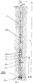
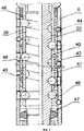
Описанный способ может быть осуществлен, в частности, с помощью предлагаемого устройства для развинчивания труб, которое, как и известное устройство-прототип, содержит корпус, механизм реверса в виде синусошарикового редуктора, входной вал которого жестко соединен с переходником, а водило установлено подвижно относительно корпуса, и механизм фиксации в виде толкателя с рядом подпружиненных якорей, подвижно установленных на расстоянии друг от друга по периметру водила.The described method can be carried out, in particular, using the proposed device for unscrewing pipes, which, like the known prototype device, contains a housing, a reverse mechanism in the form of a sinus ball reducer, the input shaft of which is rigidly connected to the adapter, and the carrier is mounted movably relative to the housing , and the locking mechanism in the form of a pusher with a number of spring-loaded anchors movably mounted at a distance from each other around the perimeter of the carrier.
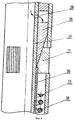
Предлагаемое устройство отличается от прототипа тем, что механизм фиксации содержит не менее двух рядов подпружиненных якорей с толкателями, причем второй и каждый последующий ряд подпружиненных якорей установлены от предыдущего ряда на расстоянии не менее двух диаметров скважины.The proposed device differs from the prototype in that the locking mechanism contains at least two rows of spring-loaded anchors with pushers, and the second and each subsequent row of spring-loaded anchors are installed from the previous row at a distance of at least two diameters of the well.
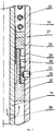
Предлагаемое устройство отличается тем, что оно дополнительно содержит механизм блокировки, состоящий из корпуса, в котором установлена жестко зубчатая муфта и концентрично полый вал с отверстиями, на котором подвижно установлены толкатель с пружиной и на шлицах нажимная зубчатая муфта, причем корпус и полый вал с одной стороны жестко соединены с полым валом и корпусом механизма фиксации, а с другой стороны - с переходником, причем полый вал жестко, а корпус подвижно.The proposed device is characterized in that it further comprises a locking mechanism consisting of a housing in which a rigid gear coupling and a concentric hollow shaft with holes are mounted, on which a pusher with a spring and a pressure gear coupling are movably mounted on the splines, the housing and the hollow shaft with one the sides are rigidly connected to the hollow shaft and the housing of the locking mechanism, and on the other hand, to the adapter, the hollow shaft is rigidly and the housing is movable.
Устройство отличается тем, что каждый толкатель с рядом подпружиненных якорей установлены на отдельном полом валу внутри отдельного корпуса, при этом якоря расположены под окнами, выполненными в корпусах, отдельные полые валы соединены друг с другом и с входным валом механизма реверса внутренними втулками, а корпусы соединены между собой и водилом механизма реверса наружными муфтами.The device is characterized in that each pusher with a number of spring-loaded anchors is mounted on a separate hollow shaft inside a separate housing, while the anchors are located under the windows made in the housings, individual hollow shafts are connected to each other and to the input shaft of the reverse mechanism by internal bushings, and the housings are connected between themselves and the carrier of the reverse mechanism by external couplings.
Существенными отличительными признаками заявляемого устройства являются следующие.Salient features of the claimed device are as follows.
1. Механизм фиксации содержит не менее двух рядов подпружиненных якорей с толкателями. Это необходимо для надежной фиксации и компенсации спиралевидной деформации в объединенной колонне, которая возникает от воздействия максимально допустимого (расчетного для данной длины прихваченной колонны) крутящего момента Мкр max и которая приводит к перекосам резьбовых соединений труб и соответственно дополнительным усилиям для развинчивания таких деформированных резьб. Кроме этого, развинчивание таких высоконагруженных деформированных резьб приводит к их интенсивному износу, уменьшающему надежность и срок службы. Чтобы уменьшить перекосы резьбовых соединений необходимо уменьшить спиралевидную деформацию объединенной колонны труб. Для этого используется центрирование подпружиненными якорями части колонны труб относительно стенок скважины, при этом, если будет использоваться один ряд якорей, то эффект практически не будет наблюдаться, т.к. один ряд якорей обеспечивает центрирование только в одном локальном месте, что может изменить только конфигурацию изгибных деформаций объединенной колонны. Когда для центрирования используется два и более ряда якорей, то происходит направленная ориентация деформированной части объединенной колонны и УРТ относительно оси скважины. Условиями такой ориентации, в основном, являются усилия, развиваемые подпружиненными якорями, величина которых должна быть достаточной, чтобы преодолеть усилие изгибающих деформаций колонны труб. Ликвидацией изгибных деформаций в части объединенной колонны, находящейся непосредственно перед местом прихвата, что обеспечивается наличием как минимум двух рядов якорей, расположенных на некотором расстоянии друг от друга, обеспечивается центрирование частей объединенной колонны выше и ниже УРТ на определенное расстояние, зависящее от величины деформации, которая, в свою очередь, зависит от длины объединенной колонны, ее жесткости, диаметра скважины, величины прилагаемого к колонне крутящего момента. Ликвидация изгибных деформаций объединенной колонны в месте прихвата, значительно улучшающая центрирование объединенной колонны и ликвидирующая перекосы резьбовых соединений труб, значительного снижает усилие, необходимое для «срыва» резьбы и развинчивания резьбового соединения без его разрушительного износа.1. The locking mechanism contains at least two rows of spring-loaded anchors with pushers. This is necessary for reliable fixation and compensation of spiral deformation in the joint column, which arises from the effect of the maximum allowable (calculated for a given length of the stuck column) torque M cr max and which leads to distortions of the pipe threaded joints and, accordingly, additional efforts to unscrew such deformed threads. In addition, the unscrewing of such highly loaded deformed threads leads to intensive wear, which reduces reliability and service life. To reduce the distortions of the threaded connections, it is necessary to reduce the spiral deformation of the joint pipe string. For this, the spring-loaded anchors center the parts of the pipe string relative to the walls of the well, and if one row of anchors is used, the effect will be practically not observed, because one row of anchors provides centering in only one local place, which can only change the configuration of the bending deformations of the joint column. When two or more rows of anchors are used for centering, then the directional orientation of the deformed part of the combined column and URT relative to the axis of the borehole occurs. The conditions for this orientation are mainly the efforts developed by the spring-loaded anchors, the value of which should be sufficient to overcome the force of bending deformations of the pipe string. Elimination of bending deformations in the part of the combined column located directly in front of the sticking point, which is ensured by the presence of at least two rows of anchors located at a certain distance from each other, ensures the centering of the parts of the combined column above and below the URT for a certain distance, which depends on the strain value, which , in turn, depends on the length of the combined string, its rigidity, the diameter of the well, the magnitude of the torque applied to the string. Elimination of bending deformations of the joint string at the sticking point, significantly improving the alignment of the joint string and eliminating the distortions of the threaded pipe joints, significantly reduces the force required to “break” the thread and unscrew the threaded joint without destructive wear.
Это значительно увеличивает надежность развинчивания резьбовых соединений прихваченной колонны именно в месте, близком к прихвату, что позволит развинтить и извлечь за один раз максимально большую по длине часть прихваченной колонны. Это повышает производительность и связанную с ней надежность всего процесса извлечения труб.This significantly increases the reliability of unscrewing the threaded joints of the stuck column exactly in the place close to the grab, which will allow to unscrew and remove at the same time the largest part of the stuck column in length. This improves productivity and the associated reliability of the entire pipe extraction process.
Для обеспечения надежной работы механизма реверса необходима надежная фиксация его водила, поэтому два и более ряда подпружиненных якорей с толкателями обеспечивают более надежную фиксацию корпуса механизма фиксации, который жестко соединен с водилом механизма реверса и тем самым увеличивает надежность работы УРТ и способа.To ensure reliable operation of the reverse mechanism, reliable fixation of its carrier is necessary, therefore two or more rows of spring-loaded anchors with pushers provide more reliable fixation of the housing of the locking mechanism, which is rigidly connected to the carrier of the reverse mechanism and thereby increases the reliability of the URT and the method.
2. Расположение рядов подпружиненных якорей так, что второй и каждый последующий ряд установлен от предыдущего ряда на расстоянии не менее двух диаметров скважины, обеспечивает ориентацию (направление) приложения усилий от рядов подпружиненных якорей на спиралевидно деформированную конструкцию объединенной колонны труб, приводящую к ликвидации или значительному уменьшению деформации и переориентированию деформированной части колонны труб возле места прихвата.2. The arrangement of the rows of spring-loaded anchors so that the second and each subsequent row is installed from a previous row at a distance of at least two diameters of the well, provides orientation (direction) of the application of force from the rows of spring-loaded anchors to the spiral-shaped design of the joint pipe string, leading to liquidation or significant reduction of deformation and reorientation of the deformed part of the pipe string near the sticking point.
Для диаметров скважины менее 100 мм жесткость объединенной колонны труб, особенно при большой ее длине, объективно значительно меньше, чем для больших диаметров, и ее влияние на деформации в резьбовых соединениях проявляется достаточно сильно. Поэтому наиболее характерно определение минимального расстояния между рядами подпружиненных якорей для объединенных колонн труб с такими малыми диаметрами.For borehole diameters less than 100 mm, the rigidity of the combined pipe string, especially when its length is large, is objectively significantly less than for large diameters, and its effect on deformations in threaded joints is quite strong. Therefore, the most characteristic is the determination of the minimum distance between the rows of spring-loaded anchors for the joined pipe columns with such small diameters.
Можно рассмотреть два предельных случая.Two limiting cases can be considered.
Первый, когда УРТ опускается непосредственно на голову трубы прихваченной колонны, находящейся рядом с местом прихвата. В этом случае расстояние между рядами подпружиненных якорей не имеет большого значения и влияния, т.к. свободную часть прихваченной колонны (до места прихвата) можно рассматривать как стержень с защемленным концом, при воздействии на незащемленный конец которого (контакт рядов подпружиненных якорей со стенками скважины) будут происходить деформация и осесимметричная ориентация продольной оси прихваченной колонны относительно продольной оси скважины. Это приведет к значительному уменьшению изгибных деформаций в резьбовых соединениях. В таком случае расстояние между рядами подпружиненных якорей будет определяться только требованиями конструктивного проектирования: габаритными размерами подпружиненных якорей и сопутствующих им конструктивных элементов (пружины, толкатели и т.д.), размерами гидравлической полости, определяемой на основании прочностного расчета, разностью диаметров корпуса механизма фиксации и полого вала.The first, when the URT falls directly onto the head of the pipe of the stuck column located near the sticking point. In this case, the distance between the rows of spring-loaded anchors does not have much significance and influence, since the free part of the stuck string (up to the sticking point) can be considered as a rod with a clamped end, when exposed to the bare clamped end (contact of the rows of spring-loaded anchors with the walls of the well), deformation and axisymmetric orientation of the longitudinal axis of the stuck string relative to the longitudinal axis of the well will occur. This will lead to a significant reduction in bending deformation in threaded joints. In this case, the distance between the rows of spring-loaded anchors will be determined only by the requirements of structural design: the dimensions of the spring-loaded anchors and associated structural elements (springs, pushers, etc.), the dimensions of the hydraulic cavity, determined on the basis of the strength calculation, the difference in diameter of the housing of the locking mechanism and hollow shaft.
Исходя из приведенных конструктивных обоснований минимальное расстояние между рядами подпружиненных якорей находится в пределах двух диаметров скважины.Based on the above structural justifications, the minimum distance between the rows of spring-loaded anchors is within two well diameters.
С другой стороны, если делать это расстояние (межу рядами подпружиненных якорей) меньшим, то появляется большая вероятность того, что усилия от подпружиненных якорей на стенку скважины могут привести к разрушению материала стенки скважины, возможному его сколу или выкрашиванию, что значительно осложнит или даже сделает невозможным фиксацию подпружиненных якорей на стенке скважины. Это будет значительно уменьшать надежность фиксации УРТ, а значит и надежность его работы.On the other hand, if you make this distance (between the rows of spring-loaded anchors) smaller, then there is a greater likelihood that the efforts from the spring-loaded anchors on the wall of the well can lead to destruction of the material of the wall of the well, its possible chipping or chipping, which will significantly complicate or even make impossible to fix spring-loaded anchors on the wall of the well. This will significantly reduce the reliability of fixing URT, and hence the reliability of its work.
Второй предельный случай - голова прихваченной колонны находится на значительном расстоянии от места прихвата. В этом случае необходимо расстояние между рядами подпружиненных якорей увеличивать, при этом опять накладываются только конструктивные ограничения, связанные с габаритами конструкции, удобством ее транспортировки, эксплуатации и технического обслуживания.The second limiting case - the head of the stuck column is at a considerable distance from the place of sticking. In this case, it is necessary to increase the distance between the rows of spring-loaded anchors, while again only structural limitations are imposed, associated with the dimensions of the structure, the convenience of its transportation, operation and maintenance.
3. Выполнение в УРТ механизма блокировки, состоящего из корпуса, в котором установлена жестко зубчатая муфта и концентрично полый вал с отверстиями, на котором подвижно установлены толкатель с пружиной и на шлицах нажимная зубчатая муфта, причем корпус и полый вал, с одной стороны, жестко соединены с полым валом и корпусом механизма фиксации, а с другой стороны, с переходником, причем полый вал жестко, а корпус подвижно, повышает сохранность УРТ от возможных боковых и вертикальных ударов при перемещении в скважине, а, следовательно, повышает его работоспособность и надежность в целом. Кроме этого, в зафиксированном (транспортном) положении механизм блокировки обеспечивает невозможность вращения полого вала относительно корпуса механизма фиксации, что обеспечивает повышение надежности УРТ при приложении вертикальных растягивающих нагрузок. Это также обеспечивает невозможность произвольного проворачивания ведомого вала при возможных зацепах в скважине при подъемах, что также повышает надежность и расширяет технологические возможности при работе УРТ.3. Implementation in the URT of a locking mechanism consisting of a housing in which a rigidly gear coupling and a concentric hollow shaft with holes are installed, on which a pusher with a spring and a pressure gear coupling are movably mounted on the splines, the housing and the hollow shaft, on the one hand, rigidly connected to the hollow shaft and the housing of the locking mechanism, and on the other hand, to the adapter, and the hollow shaft is rigid, and the housing is movable, increases the safety of URT from possible side and vertical impacts when moving in the well, and therefore increases its performance and reliability in general. In addition, in the locked (transport) position, the locking mechanism makes it impossible to rotate the hollow shaft relative to the housing of the locking mechanism, which improves the reliability of the URT when applying vertical tensile loads. This also ensures the impossibility of arbitrary rotation of the driven shaft with possible hooks in the well during lifts, which also increases reliability and extends the technological capabilities during operation of the URT.
Предложенный способ и устройство для его осуществления более подробно раскрываются приведенными ниже примерами, которые, однако, не исчерпывают всех возможных вариантов реализации.The proposed method and device for its implementation are disclosed in more detail by the following examples, which, however, do not exhaust all possible implementation options.
Изобретение иллюстрируется чертежами, где на фиг.1 изображена схема реализации способа; на фиг.2 схематично изображено УРТ; на фиг.3 изображена часть конструкции механизма блокировки УРТ; на фиг.4 изображено транспортное положение подпружиненных якорей механизма фиксации УРТ; на фиг.5 изображено рабочее положение подпружиненных якорей механизма фиксации УРТ; на фиг.6 изображен механизм реверса УРТ.The invention is illustrated by drawings, where figure 1 shows a diagram of the implementation of the method; figure 2 schematically shows the URT; figure 3 shows part of the design of the locking mechanism of the URT; figure 4 shows the transport position of the spring-loaded anchors of the fixing mechanism of the URT; figure 5 shows the working position of the spring-loaded anchors of the fixing mechanism of the URT; figure 6 shows the reverse mechanism of URT.
Предлагаемый способ извлечения труб из скважины заключается в следующем:The proposed method of extracting pipes from the well is as follows:
- проводят профиле - или кавернометрию скважины 1 и определяют верхнюю границу прихвата 2 и ближайшее от головы прихваченной колонны 3 место в стволе (неразработанное, с устойчивыми и прочными стенками) для надежной фиксации УРТ 4;- conduct a profile - or cavernometry of the
- вычисляют длину соединительной трубы 5 и устанавливают ее между выходным валом 6 механизма реверса 7 УРТ 4 и присоединяемым к нему ловильным инструментом 8 исходя из требования, чтобы при постановке ловильного инструмента 8 на голову прихваченной колонны 3 механизм фиксации 9 УРТ 4 находился в определенном предыдущим действием месте, обеспечивающем его надежную фиксацию в скважине 1;- calculate the length of the connecting
- вычисляют L1 - длину свободной части прихваченной колонны 3 от места прихвата 2 до механизма реверса УРТ;- calculate L1 - the length of the free part of the
- вычисляют L2 - длину составной колонны от места прихвата 2 до привода вращения колонны на поверхности устья скважины;- calculate L2 - the length of the composite column from the
- вычисляют M1 - максимально допустимый крутящий момент для конструкции свободной части прихваченной колонны 3 длиной L1;- calculate M1 - the maximum allowable torque for the construction of the free part of the
- вычисляют Р - вес конструкции составной колонны L2, с учетом веса УРТ 4;- calculate P - the weight of the structure of the composite columns L2, taking into account the weight of
- вычисляют F - максимально допустимое растягивающее усилие для конструкции составной колонны длиной L2, с учетом конструкции УРТ 4;- calculate F - the maximum allowable tensile force for the construction of a composite column of length L2, taking into account the design of
- осуществляют спуск на правых рабочих трубах 10 на расчетную глубину в скважину 1 УРТ 4 до контакта ловильного инструмента 8 с головой прихваченной колонны 3 труб;- carry out the descent on the
- выполняют фиксацию УРТ 4 в расчетном месте скважины 1 путем повышения давления промывочной жидкости, подаваемой через колонну рабочих труб 10 в механизм фиксации 9 и выдвижения подпружиненных якорей 11 до контакта (упора) со стенками скважины 1;- perform fixing
- производят навинчивание влево ловильного инструмента 8 на голову прихваченной колонны 3 труб под действием преобразованного механизмом реверса 7 правого вращения колонны рабочих труб 10 в левое вращение ловильного инструмента 8;- make screwing of the
- производят расфиксирование УРТ 4 понижением давления промывочной жидкости и возвращением подпружиненных якорей 11 механизма фиксации 9 в исходное (транспортное) положение;-
- к голове рабочих труб 10 приводом (не показан) на устье скважины 1 прикладывают расчетное растягивающее усилие F;- the estimated tensile force F is applied to the head of the working
- выполняют фиксацию УРТ 4 в скважине 1 путем повышения давления промывочной жидкости через колонну рабочих труб 10 в механизм фиксации 9 и выдвижения подпружиненных якорей 11 до контакта (упора) со стенками скважины 1;- perform fixing
- прикладывают приводом вращения (не показан) крутящий момент Мкр к колонне рабочих труб 10, величина которого соответствует вычисленному значению M1 и находится в пределах- apply a rotation drive (not shown) with a torque M cr to the column of working
0,9 M1/i × q≤Мкр≤0,95 M1/i × q,0.9 M1 / i × q≤M cr ≤0.95 M1 / i × q,
где M1 - максимально допустимый крутящий момент для конструкции свободной части прихваченной колонны длиной L1 от места прихвата до механизма реверса УРТ,where M1 is the maximum allowable torque for the construction of the free part of the stuck column of length L1 from the point of sticking to the reverse mechanism of the URT,
i - передаточное отношение синусошарикового редуктора,i is the gear ratio of the sinus ball reducer,
q - кпд синусошариковой передачи.q is the efficiency of the sinus ball transfer.
- производят плавное уменьшение растягивающего усилия F до величины Р, если при этом не начинается развинчивание колонны в резьбовом соединении на верху прихваченной трубы, производят последовательные ступенчатые снижения величины растягивающего усилия F=P на величину, соответствующую весу трубы в свободной части прихваченной колонны 3, начиная от величины веса трубы, привинченной к прихваченной трубе, и после каждого снижения величины растягивающего усилия контролируют начало развинчивания резьбового соединения по показаниям датчика на приводе вращения (не показан) колонны рабочих труб 10 на поверхности скважины;- produce a smooth decrease in the tensile force F to a value of P, if this does not begin to unscrew the column in the threaded connection on top of the stuck pipe, produce sequential stepwise decrease in the value of the tensile force F = P by the value corresponding to the weight of the pipe in the free part of the
- после развинчивания резьбового соединения извлекают из скважины 1 на поверхность отвинченную часть прихваченной колонны 3 труб.- after unscrewing the threaded connection, the unscrewed part of the
После развинчивания и подъема на поверхность свободной части прихваченной колонны 3 длиной L1 принимается решения о прекращении ликвидации аварии, а если извлечена только часть прихваченной колонны 3, то все операции повторяют.After loosening and lifting to the surface of the free part of the
Таким образом, изобретение (способ) обеспечивает повышение надежности и производительности извлечения из скважины колонны прихваченных труб.Thus, the invention (method) provides an increase in the reliability and productivity of extraction from the well of a string of stuck pipes.
Наилучшим образом способ реализуется предлагаемым УРТ для извлечения из скважины колонны прихваченных труб.In the best way, the method is implemented by the proposed URT for extracting from the well of a string of stuck pipes.
УРТ 4 состоит (фиг.2) из механизма блокировки 12, механизма фиксации 9 и механизма реверса 7 с переходным механизмом 13.
Механизм блокировки 12 и механизм фиксации 9 расположены на полом составном валу 14 в составном корпусе 15. Части полого составного вала 14 механизма блокировки 12 и механизма фиксации 9 соединены внутренними резьбовыми втулками 16, а части составного корпуса 15 соединены наружными резьбовыми ниппелями 17. Полый составной вал 14 в верхней части жестко соединен с переходником 18, предназначенным для соединения с колонной рабочих 10 труб. Полый составной вал 14 в нижней части соединен муфтой 19 с полым входным валом 20 механизма реверса 7.The locking mechanism 12 and the locking mechanism 9 are located on the hollow
Механизм реверса 7 выполнен в виде синусошарикового редуктора, выходной вал 6 которого соединен в нижней части с корпусом 21 переходного механизма 13, в котором на шлицевом соединении 22 установлен клапан 23 с переходником 24 для присоединения ловильного инструмента 8. При необходимости увеличения расстояния между УРТ 4 и ловильным инструментом 8 на переходник 24 устанавливается соединительная труба 5.The reverse mechanism 7 is made in the form of a sinus ball reducer, the
Механизм блокировки 12 состоит (фиг.3) из нажимной муфты 25 с зубками 26, установленной на шлицах 27 на полом составном валу 14 с отверстиями 28, муфты 29 с зубками 30, жестко закрепленной в составном корпусе 15 штифтами 31, толкателя 32 и возвратной пружины 33.The locking mechanism 12 consists (Fig. 3) of a
Механизм блокировки 12 обеспечивает при повышении давления промывочной жидкости до заданной (определенной) величины сжатие возвратной пружины 33, перемещение толкателя 32 и расцепление зубков 26 и 30 соответствующих муфт 25 и 29, что приводит к разъединению кинематической связи между полым составным валом 14 и составным корпусом 15. При этом правое вращение рабочей колонны 10 труб передается через полый составной вал 14 к входному валу 20 механизма реверса 7, в котором оно изменяется на левое вращение выходного вала 6 и соответственно ловильного инструмента 8.The locking mechanism 12 provides, with increasing pressure of the flushing fluid to a predetermined (defined) value, compression of the
При снижении давления промывочной жидкости ниже заданной величины механизм блокировки 12 устанавливает механическую (кинематическую) связь между полым составным валом 14 и составным корпусом 15, в результате перемещения толкателя 32 под действием пружины 33 и вхождения зубков 26 муфты 25, жестко связанной с полым составным валом 14 через шлицевое соединение 27, в зацепление с зубками 30 муфты 29, жестко закрепленной в составном корпусе 15 штифтами 31.When the pressure of the washing fluid decreases below a predetermined value, the locking mechanism 12 establishes a mechanical (kinematic) connection between the hollow
Механизм фиксации 9 состоит (фиг.4, 5) из двух рядов подпружиненных якорей 11, расположенных на одинаковом расстоянии друг от друга по окружности в окнах 34 составного корпуса 15 и опирающихся на конусную часть толкателей 35. Толкатели 35 установлены с возможностью продольного перемещения на полом составном валу 14 с отверстиями 28.The locking mechanism 9 consists (Figs. 4, 5) of two rows of spring-loaded
В каждом подпружиненном якоре 11 каждого ряда подвижно установлена в профилированном пазу (типа «ласточкин хвост» - не показан) плоская пружина 36, один конец которой расположен в муфте 37, установленной на полом составном валу 14. На плоские пружины 36 каждого рядов якорей 11 надета круглая пружина 38, зафиксированная одним концом возле муфты 37.In each spring-loaded
Расстояние между рядами якорей 11 не менее двух диаметров скважины 1.The distance between the rows of
Механизм фиксации 9 предназначен для фиксации от перемещений составного корпуса 15 в скважине 1 и обеспечения работы механизма реверса 7.The locking mechanism 9 is designed to fix from the movements of the
Механизм реверса 7 состоит (фиг.6) из полого вала 20 с канавками 39, промежуточного вала - водила 40 с пазами 41, охватывающих втулок 42 с синусоидальными беговыми дорожками 43, жестко закрепленных внутри полого выходного вала 6 штифтами 44, шаровых сателлитов 45, подшипника 46, нижнего 47 и верхнего 48 уплотнений. Водило 40 жестко соединено с составным корпусом 15 механизма фиксации 9 и образует с ним ступенчатую втулку.The reverse mechanism 7 consists (Fig. 6) of a
Механизм реверса 7 предназначен для изменения правого вращения рабочей колонны 10 труб на левое вращение выходного вала 6 с передаточным отношением i.The reverse mechanism 7 is designed to change the right rotation of the working
Переходной механизм 13 состоит из корпуса 21 с дроссельной шайбой 49, в котором на шлицевом соединении 22 установлен с пружиной 50 клапан 23 с конусом 51, системой каналов 52 и переходником 24 для присоединения напрямую или через соединительную трубу 5 к ловильному инструменту 8. Корпус 21 жестко соединен с выходным валом 6 механизма реверса 7.The transition mechanism 13 consists of a housing 21 with a throttle washer 49, in which a valve 23 with a cone 51, a channel system 52 and an adapter 24 for connecting directly or through a connecting
Рабочие (бурильные) трубы и механизм блокировки имеют правую резьбу, а соединения деталей УРТ и ловильного инструмента имеют левую резьбу.The working (drill) pipes and the locking mechanism have a right-hand thread, and the connections of the URT parts and the fishing tool have a left-hand thread.
Переходной механизм 13 предназначен для перекрытия расхода промывочной жидкости, проходящей через полый составной вал 14 в механизмах блокировки 12 и фиксации 9, входной вал 20 механизма реверса 7, дроссельную шайбу 49 и систему каналов 52 клапана 23, в момент постановки рабочей колонны 10 труб на голову прихваченной колонны 3, а также для передачи вращения от рабочей колонны 10 труб ловильному инструменту 8 и компенсации осевого перемещения колонны прихваченных труб 3 при ее развинчивании.The transition mechanism 13 is designed to shut off the flow of flushing fluid passing through the hollow
Извлечение труб из скважины по способу с применением УРТ производят следующим образом.Removing pipes from the well by the method using URT is as follows.
По данным геофизических исследований в cквaжинe 1 или по имеющемуся керновому материалу определяют устойчивый ненарушенный участок в скважине 1, наиболее близко расположенный к «голове» прихваченной колонны 3 труб, в котором можно надежно зафиксировать УРТ 4. Затем вычисляют длину соединительной трубы 5, которая одним концом присоединяется к переходнику 24 клапана 23, а другим концом соединяется с ловильным инструментом 8. Соединительная труба 5 должна иметь такую длину, чтобы при фиксации УРТ 4 на участке скважины 1 ловильный инструмент 8 располагался на голове прихваченной колонны 3 труб.According to geophysical studies in well 1 or from existing core material, a stable undisturbed section in
Если участок скважины 1 обеспечивает надежную фиксацию УРТ 4 в месте его расположения при установке ловильного инструмента 8 на «голову» прихваченной колонны 3 труб, то необходимость в установке соединительной трубы 5 отпадает и ловильный инструмент 8 устанавливают прямо на переходник 24.If the
Снаряженное УРТ 4 на рабочей колонне 10 труб устанавливают на голову прихваченной колонны 3 труб. При этом сжимается пружина 50 переходного механизма 13 и клапан 23, перемещаясь, перекрывает конусом 51 отверстие дроссельной шайбы 49, что приводит к повышению давления промывочной жидкости в УРТ 4. Под давлением промывочная жидкость через полый составной вал 14 и отверстия 28 поступает в механизмы блокировки 12 и фиксации 9.
Подают (нагнетают) по рабочей колонне 10 труб промывочную жидкость, которая через отверстия 28 в полом составном валу 14 поступает во внутренние полости механизма фиксации 9 и оказывает давление на толкатели 35, которые, перемещаясь, выдвигают подпружиненные якоря 11 в окна 34 до упора со стенками скважины 1 и тем самым фиксируют составной корпус 15. Одновременно промывочная жидкость поступает во внутреннюю полость механизма блокировки 12 и оказывает давление на толкатель 32, который, перемещаясь, передвигает нажимную муфту 25, выводя ее зубки 26 из зацепления с зубками 30 муфты 29.Flushing fluid is supplied (injected) through the working
Затем рабочей колонне 10 труб на устье скважины 1 придают правое вращение, которое через полый вал 14 передается в механизм реверса 7, в котором водило 40, жестко соединенное с зафиксированным в стволе скважины 1 составным корпусом 15, также оказывается зафиксированным от возможных перемещений. В УРТ приводятся в движение шаровые сателлиты 45, которые, перекатываясь по канавкам 39 на входном валу 20, взаимодействуя с пазами 41 водила 40 и синусоидальными беговыми дорожками 43 охватывающих втулок 42, заставляют последние и жестко связанный с ними штифтами 44 полый выходной вал 6 вращаться в левую сторону. Подшипник 46 воспринимает осевые нагрузки, а нижнее 47 и верхнее 48 уплотнения предохраняют механизм реверса 7 от воздействия внешней среды. Механизм реверса 7 изменяет правое вращение рабочей колонны 10 труб на левое вращение ловильного инструмента 8, который навинчивается на «голову» прихваченной колонны 3 труб. При этом осевое перемещение переходника 24 обеспечивается клапаном 23.Then, the working
Прекращают вращение рабочей колонны 10 труб и сбрасывают давление промывочной жидкости. При снижении давления промывочной жидкости в механизме фиксации 9 плоская пружина 36 возвращает толкатель 35 в исходное положение, а подпружиненные якоря 11 перемещаются внутрь составного корпуса 15. При этом в механизме блокировки 12 возвратная пружина 33 возвращает нажимную муфту 25 на место, вводя в зацепление зубки 26 и 30. Происходит фиксация составного корпуса 15 относительно ствола скважины 1.Stop the rotation of the working
Производят необходимые для осуществления способа вычисления длин, весовых и нагрузочных параметров объединенной колонны и ее частей:Produce the necessary to implement the method of calculating the lengths, weight and load parameters of the combined columns and its parts:
L1 - длину свободной части прихваченной колонны от места прихвата до механизма реверса УРТ;L1 is the length of the free part of the stuck column from the sticking point to the reversal mechanism of URT;
L2 - длину составной колонны от места прихвата до привода вращения колонны на поверхности устья скважины;L2 is the length of the composite column from the sticking point to the rotation of the column on the surface of the wellhead;
M1 - максимально допустимый крутящий момент для конструкции свободной части прихваченной колонны длиной L1;M1 is the maximum allowable torque for the construction of the free part of the stuck column length L1;
Р - вес конструкции составной колонны длиной L2, с учетом веса УРТ 4;P is the weight of the construction of a composite column of length L2, taking into account the weight of
F - максимально допустимое растягивающее усилие для конструкции составной колонны длиной L2, с учетом конструкции УРТ 4.F is the maximum allowable tensile force for the construction of a composite column of length L2, taking into account the design of
К голове рабочей колонны 10 труб на устье скважины 1 прикладывают направленное вверх максимально допустимое растягивающее усилие F, превосходящее сжимающую осевую нагрузку от веса Р составной колонны рабочих труб 10 в месте резьбового соединения, наиболее близко расположенного к прихвату 2.To the head of the working
Подают (нагнетают) по рабочей колонне 10 труб промывочную жидкость, которая через отверстия 28 в полом составном валу 14 поступает во внутренние полости механизма фиксации 9 и оказывает давление на толкатели 35, которые, перемещаясь, выдвигают подпружиненные якоря 11 в окна 34 до упора со стенками скважины 1. Осуществляется фиксация УРТ 4. Одновременно промывочная жидкость поступает во внутреннюю полость механизма блокировки 12 и оказывает давление на толкатель 32, который, перемещаясь, передвигает нажимную муфту 25, выводя ее зубки 26 из зацепления с зубками 30 муфты 29. Происходит расфиксирование полого составного вала 14, т.е. происходит разъединение кинематической связи с составным корпусом 15.Flushing fluid is supplied (injected) through the working
Затем рабочей колонне 10 труб на устье скважины 1 придают правое вращение, которое через полый вал 14 передается в механизм реверса 7, в котором водило 40, жестко соединенное с зафиксированным в стволе скважины 1 составным корпусом 15, также оказывается зафиксированным от возможных перемещений. В механизме реверса 7 приводятся в движение шаровые сателлиты 45, которые, перекатываясь по канавкам 39 на входном валу 20, взаимодействуя с пазами 41 водила 40 и синусоидальными беговыми дорожками 43 охватывающих втулок 42, заставляют последние и жестко связанный с ними штифтами 44 полый выходной вал 6, вращаться в левую сторону. Механизм реверса 7 изменяет правое вращение рабочей колонны 10 труб на левое вращение прихваченной колонны 3 труб.Then, the working
Контролируют, чтобы величина прикладываемого крутящего момента Мкр к колонне рабочих труб 10 соответствовала вычисленному значению М1 и определяемому из неравенстваIt is controlled that the magnitude of the applied torque M cr to the column of working
0,9 М1/i × q≤Мкр≤0,95 М1/i × q,0.9 M1 / i × q≤M cr ≤0.95 M1 / i × q,
где М1 - максимально допустимый крутящий момент для конструкции свободной части прихваченной колонны длинной L1 от места прихвата до механизма реверса УРТ,where M1 is the maximum allowable torque for the construction of the free part of the stuck column of length L1 from the point of sticking to the reverse mechanism of the URT,
i - передаточное отношение синусошарикового редуктора,i is the gear ratio of the sinus ball reducer,
q - кпд синусошариковой передачи,q is the efficiency of the sinus ball transfer,
и на устье скважины 1 производят плавное снижение растягивающего усилия F до величины Р. Реактивный момент от вращения выходного вала 6 механизма реверса 7 воспринимается якорями 11 в окнах 34 механизма фиксации 9. Так как направленное вверх усилие F компенсирует в месте резьбового соединения сжимающую осевую нагрузку от веса Р составной колонны L2, то в этом резьбовом соединении происходит так называемое «обнуление» веса. Под действием крутящего момента, передаваемого рабочей колонной 10 труб и увеличенного механизмом реверса 7 на передаточное число синусошариковой передачи до величины максимально возможного для конкретной конструкции составной колонны L2 значения Мкр, происходит «срыв» и развинчивание резьбового соединения.and at the
Контролируют начало развинчивания резьбового соединения по показаниям датчика на приводе вращения (не показан) колонны рабочих труб 10 на поверхности скважины 1. При развинчивании труб осевое перемещение прихваченной колонны 3 труб через переходник 24 обеспечивается (компенсируется) клапаном 23.Control the start of unscrewing the threaded connection according to the sensor on the rotation drive (not shown) of the working
После развинчивания резьбового соединения прекращают вращение рабочей колонны 10 труб и сбрасывают давление промывочной жидкости. При снижении давления промывочной жидкости в механизме блокировки 12 возвратная пружина 33 возвращает нажимную муфту 25 на место, вводя в зацепление зубки 26 и 30. Этим создается жесткая кинематическая связь и происходит фиксация составного корпуса 15 относительно полого составного вала 14. В механизме фиксации 9 плоская пружина 36 возвращает толкатель 35 в исходное положение, а якоря 11 перемещаются внутрь составного корпуса 15. Происходит расфиксирование УРТ 4 в скважине 1 и осуществляют извлечение на поверхность на рабочих трубах 10 отвинченной части прихваченной колонны 3 труб.After unscrewing the threaded connection, the rotation of the working
Если извлечена не вся свободная часть прихваченной колонны 3, то все операции повторяют, при этом определяют новое место фиксации УРТ и вновь рассчитывают параметры L1, L2, F, Р, Мкр и М1.If not all the free part of the
Если при плавном снижении растягивающего усилия F до величины Р не начинается развинчивание прихваченной колонны 3 труб в резьбовом соединении на верху прихваченной трубы, что определяется по показаниям датчика на приводе вращения (не показан) колонны рабочих 10 труб на поверхности скважины 1, производят ступенчатое (резкое) снижение растягивающего усилия F=P на величину, соответствующую весу трубы в свободной части прихваченной колонны 3, начиная от трубы привинченной к прихваченной трубе. При этом «нулевое» сечение, т.е. место, где вес составной колонны труб и растягивающее усилие F (направленное к поверхности) равны по величине и направлены в разные стороны, перемещается к верхнему резьбовому соединению трубы, привинченной к прихваченной трубе. Контролируют начало развинчивания резьбового соединения по показаниям датчика на приводе вращения (не показан) колонны рабочих труб 10 на поверхности скважины и осуществляют извлечение на поверхность на рабочих трубах 10 отвинченной части прихваченной колонны 3 труб.If, with a smooth decrease in the tensile force F to a value of P, the sticking of the
Если развинчивание не происходит, то опять ступенчато снижают растягивающее усилие F на величину, соответствующую весу следующей по направлению вверх, трубы в свободной части прихваченной колонны 3 и контролируют начало развинчивания резьбового соединения.If the unscrewing does not occur, then again the tensile force F is reduced stepwise by the amount corresponding to the weight of the next upward pipe in the free part of the
Заявляемое техническое решения является оригинальным, не вытекает очевидным образом из существующего уровня техники и соответствует требованиям «изобретательский уровень».The claimed technical solution is original, does not follow obviously from the existing level of technology and meets the requirements of "inventive step".
Таким образом, заявляемое техническое решение полностью выполняет поставленную задачу повышения производительности и надежности извлечения из скважины колонны прихваченных труб с применением колонны рабочих труб с правой резьбой с присоединенным к ней УРТ с соединительной трубой и ловильным инструментом.Thus, the claimed technical solution fully fulfills the task of increasing productivity and reliability of extracting from the well string of stuck pipes using a string of working pipes with a right-hand thread with an attached URT with a connecting pipe and fishing tool.
Заявляемое техническое решение на настоящее время не известно в Российской Федерации и за рубежом и соответствует требованиям критерия «новизна».The claimed technical solution is currently not known in the Russian Federation and abroad and meets the requirements of the criterion of "novelty."
Техническое решение может быть реализовано промышленным способом в условиях серийного производства с использованием известных технических средств, технологий и материалов и соответствует требованиям критерия «промышленная применимость».The technical solution can be implemented industrially in mass production using well-known technical means, technologies and materials and meets the requirements of the criterion of "industrial applicability".
Предлагаемое изобретение соответствует «промышленной применимости», т.к. принцип работы устройства прошел апробацию в производственных условиях с положительным результатом, имеются акты производственных и промышленных испытаний опытного образца УРТ.The present invention meets the "industrial applicability", because the principle of operation of the device has been tested in a production environment with a positive result, there are acts of industrial and industrial testing of a prototype of URT.
Предлагаемое изобретение может быть использовано при ликвидации аварий, связанных с прихватом труб при бурении, а также при капитальном ремонте скважин.The present invention can be used in the elimination of accidents associated with sticking pipes during drilling, as well as in overhaul of wells.
Claims (3)
вычисляют L1 - длину свободной части прихваченной колонны от места прихвата до механизма реверса УРТ;
вычисляют L2 - длину составной колонны от места прихвата до привода вращения колонны на поверхности устья скважины;
вычисляют M1 - максимально допустимый крутящий момент для конструкции свободной части прихваченной колонны длиной L1;
вычисляют Р - вес конструкции составной колонны длиной L2 с учетом веса УРТ;
вычисляют F - максимально допустимое растягивающее усилие для конструкции составной колонны длиной L2 с учетом конструкции УРТ,
а после установки и навинчивания ловильного инструмента на голову колонны прихваченных труб и расфиксирования УРТ в скважине понижением давления промывочной жидкости к голове рабочих труб на устье скважины прикладывают максимально допустимое для конструкции составной колонны растягивающее усилие F и после фиксации УРТ в скважине приводом вращения прикладывают крутящий момент Мкр к колонне рабочих труб величиной Ml и производят плавное уменьшение растягивающего усилия F до величины Р, если при этом не начинается развинчивание колонны в резьбовом соединении наверху прихваченной трубы, производят последовательные ступенчатые снижения растягивающего усилия F=P на величину, соответствующую весу трубы в свободной части прихваченной колонны, начиная от веса трубы, привинченной к прихваченной трубе, и после каждого снижения величины растягивающего усилия контролируют начало развинчивания резьбового соединения по показаниям соответствующего датчика на приводе вращения колонны рабочих труб на поверхности скважины.1. A method of extracting pipes from a well, including the descent on the right working pipes to the calculated depth into the well of a device consisting of a locking mechanism and a reverse mechanism, to the output shaft of which a fishing tool with a left thread is connected through an adapter and a connecting pipe until the fishing tool contacts head of the stuck pipe string, fixing the device in the calculated location of the wellbore by supplying flushing fluid through the working pipe string to the mechanism for fixing and extending the spring-loaded anchors to stop with the borehole, screwing the fishing tool to the left of the stuck pipe string under the action of the reverse rotation of the right rotation of the working pipe string into the left rotation of the fishing tool, unscrewing the thread in the pipe connection of the stuck string, unlocking the device as a result of pressure relief of the flushing fluid and the return of spring-loaded anchors the mechanism of fixation in the initial position, the extraction from the wellbore to the surface unscrewed from the stuck string hour and pipes, characterized in that, after determining the upper limit of sticking and fixing mechanism URT location in the barrel and calculating the length of the connection pipe
calculate L1 - the length of the free part of the stuck column from the sticking point to the reversal mechanism of the URT;
calculate L2 - the length of the composite string from the sticking point to the drive rotation of the column on the surface of the wellhead;
calculate M1 - the maximum allowable torque for the construction of the free part of the stuck column length L1;
calculate P is the weight of the structure of the composite columns of length L2, taking into account the weight of the URT;
calculate F is the maximum allowable tensile force for the construction of a composite column of length L2, taking into account the design of the URT,
and after installing and screwing the fishing tool onto the head of the string of stuck pipes and unlocking the URT in the well by lowering the pressure of the flushing fluid to the head of the working pipes at the well head, the tensile force F, which is most acceptable for the construction of the composite string, is applied and, after the URT is fixed in the well by a rotation drive, apply torque M cr to the column of working pipes of size Ml and produce a smooth decrease in tensile force F to a value of P, if this does not begin to unscrew the column in the threaded connection at the top of the stuck pipe, successive stepwise reductions of the tensile force F = P are made by an amount corresponding to the weight of the pipe in the free part of the stuck pipe, starting from the weight of the pipe screwed to the stuck pipe, and after each decrease in the tensile force, the start of unscrewing of the threaded connection is controlled according to the testimony of the corresponding sensor on the drive rotation of the column of working pipes on the surface of the well.
Priority Applications (1)
| Application Number | Priority Date | Filing Date | Title |
|---|---|---|---|
| RU2007116352/03A RU2362003C2 (en) | 2007-05-03 | 2007-05-03 | Procedure for removing pipes from well and facility for implementation of this procedure |
Applications Claiming Priority (1)
| Application Number | Priority Date | Filing Date | Title |
|---|---|---|---|
| RU2007116352/03A RU2362003C2 (en) | 2007-05-03 | 2007-05-03 | Procedure for removing pipes from well and facility for implementation of this procedure |
Publications (2)
| Publication Number | Publication Date |
|---|---|
| RU2007116352A RU2007116352A (en) | 2008-11-20 |
| RU2362003C2 true RU2362003C2 (en) | 2009-07-20 |
Family
ID=40240724
Family Applications (1)
| Application Number | Title | Priority Date | Filing Date |
|---|---|---|---|
| RU2007116352/03A RU2362003C2 (en) | 2007-05-03 | 2007-05-03 | Procedure for removing pipes from well and facility for implementation of this procedure |
Country Status (1)
| Country | Link |
|---|---|
| RU (1) | RU2362003C2 (en) |
Cited By (1)
| Publication number | Priority date | Publication date | Assignee | Title |
|---|---|---|---|---|
| RU2781432C1 (en) * | 2018-12-18 | 2022-10-12 | Хэллибертон Энерджи Сервисиз, Инк. | Hoisting tool and method for extracting a downhole tool |
Families Citing this family (1)
| Publication number | Priority date | Publication date | Assignee | Title |
|---|---|---|---|---|
| CN112482990A (en) * | 2020-11-23 | 2021-03-12 | 新汶矿业集团设计研究院有限公司 | Drilling equipment is used in coal exploitation |
-
2007
- 2007-05-03 RU RU2007116352/03A patent/RU2362003C2/en not_active IP Right Cessation
Cited By (1)
| Publication number | Priority date | Publication date | Assignee | Title |
|---|---|---|---|---|
| RU2781432C1 (en) * | 2018-12-18 | 2022-10-12 | Хэллибертон Энерджи Сервисиз, Инк. | Hoisting tool and method for extracting a downhole tool |
Also Published As
| Publication number | Publication date |
|---|---|
| RU2007116352A (en) | 2008-11-20 |
Similar Documents
| Publication | Publication Date | Title |
|---|---|---|
| CN103726804B (en) | Hydraulic packer and mounting method thereof | |
| US20070151732A1 (en) | Downhole impact generator and method for use of same | |
| NO20150057A1 (en) | Method of temporarily separating a first borehole portion of a borehole from a second borehole portion of the borehole | |
| WO2012100019A1 (en) | Tubular running device and method | |
| CN106639963A (en) | Degradable packer, multi-stage layering fracturing pipe column and fracturing construction method thereof | |
| CN110984859A (en) | Radial horizontal drilling and sand prevention well completion tool and method | |
| NO343616B1 (en) | METHOD AND COMPOSITION FOR ANCHORING A DOWN HOLE TOOL IN A WELL HOLE, AND AN ACTIVATION COMPOSITION TO ENABLE AN ANCHOR DOWN HOLE | |
| US10041308B2 (en) | Oilfield tubular connection system and method | |
| NO317038B1 (en) | Device for placing a tool in a well | |
| WO2014066587A2 (en) | Anchor latch on-off for sucker rods | |
| CN111101884A (en) | Device and method for extracting cannula | |
| US5307886A (en) | Method for casing a hole drilled in a formation | |
| RU2362003C2 (en) | Procedure for removing pipes from well and facility for implementation of this procedure | |
| CA2320558C (en) | Motion compensator for drilling from a floater | |
| CN111980610B (en) | CO 2 Water alternate injection well completion pipe column, well completion method thereof and service pipe column | |
| CN206707664U (en) | A kind of screw rod hydraulic returnable fishing tool | |
| CN103437709B (en) | Sleeve pipe driving head is utilized to carry out the method for casing job | |
| US20230392464A1 (en) | Controllable downhole drilling and completion tool separating device and their method of use | |
| EP3049610A1 (en) | Manipulation tool and method of using same, and an adapter for use together with the manipulation tool | |
| CN101368474A (en) | Mechanical dragging type anti-propping slips | |
| CN111411914A (en) | Blowout prevention blanking plug for shaft | |
| CN103437708B (en) | Be applicable to the sleeve pipe driving head of casing drilling | |
| CN103437707A (en) | Guiding and locking mechanism suitable for casing pipe driving head | |
| CN203559776U (en) | Guiding and locking mechanism suitable for driving head of sleeve pipe | |
| RU2815800C1 (en) | Downhole pipe disconnector (versions) |
Legal Events
| Date | Code | Title | Description |
|---|---|---|---|
| MM4A | The patent is invalid due to non-payment of fees |
Effective date: 20090520 |
|
| NF4A | Reinstatement of patent |
Effective date: 20101010 |
|
| MM4A | The patent is invalid due to non-payment of fees |
Effective date: 20160504 |