RU2359407C2 - Method for elimination of fixed bias for gsm receiver based on zero intermediate frequency with digital correction of frequency bias - Google Patents
Method for elimination of fixed bias for gsm receiver based on zero intermediate frequency with digital correction of frequency bias Download PDFInfo
- Publication number
- RU2359407C2 RU2359407C2 RU2005115571/09A RU2005115571A RU2359407C2 RU 2359407 C2 RU2359407 C2 RU 2359407C2 RU 2005115571/09 A RU2005115571/09 A RU 2005115571/09A RU 2005115571 A RU2005115571 A RU 2005115571A RU 2359407 C2 RU2359407 C2 RU 2359407C2
- Authority
- RU
- Russia
- Prior art keywords
- bias
- rotator
- digital
- phase
- frequency
- Prior art date
Links
Images

Classifications
-
- H—ELECTRICITY
- H04—ELECTRIC COMMUNICATION TECHNIQUE
- H04B—TRANSMISSION
- H04B1/00—Details of transmission systems, not covered by a single one of groups H04B3/00 - H04B13/00; Details of transmission systems not characterised by the medium used for transmission
- H04B1/06—Receivers
- H04B1/16—Circuits
- H04B1/30—Circuits for homodyne or synchrodyne receivers
-
- H—ELECTRICITY
- H03—ELECTRONIC CIRCUITRY
- H03D—DEMODULATION OR TRANSFERENCE OF MODULATION FROM ONE CARRIER TO ANOTHER
- H03D3/00—Demodulation of angle-, frequency- or phase- modulated oscillations
- H03D3/007—Demodulation of angle-, frequency- or phase- modulated oscillations by converting the oscillations into two quadrature related signals
- H03D3/008—Compensating DC offsets
-
- H—ELECTRICITY
- H04—ELECTRIC COMMUNICATION TECHNIQUE
- H04L—TRANSMISSION OF DIGITAL INFORMATION, e.g. TELEGRAPHIC COMMUNICATION
- H04L25/00—Baseband systems
- H04L25/02—Details ; arrangements for supplying electrical power along data transmission lines
- H04L25/06—Dc level restoring means; Bias distortion correction ; Decision circuits providing symbol by symbol detection
- H04L25/061—Dc level restoring means; Bias distortion correction ; Decision circuits providing symbol by symbol detection providing hard decisions only; arrangements for tracking or suppressing unwanted low frequency components, e.g. removal of dc offset
- H04L25/062—Setting decision thresholds using feedforward techniques only
-
- H—ELECTRICITY
- H04—ELECTRIC COMMUNICATION TECHNIQUE
- H04L—TRANSMISSION OF DIGITAL INFORMATION, e.g. TELEGRAPHIC COMMUNICATION
- H04L27/00—Modulated-carrier systems
- H04L27/18—Phase-modulated carrier systems, i.e. using phase-shift keying
- H04L27/22—Demodulator circuits; Receiver circuits
Abstract
Description
ССЫЛКИ НА РОДСТВЕННЫЕ ЗАЯВКИ НА ПАТЕНТLINKS TO RELATED PATENT APPLICATIONS
Настоящая заявка на патент притязает на приоритет предварительной заявки на патент США № 60/421223, поданной 25 октября 2002 года.This patent application claims the priority of provisional patent application US No. 60/421223, filed October 25, 2002.
ОБЛАСТЬ ТЕХНИКИ, К КОТОРОЙ ОТНОСИТСЯ ИЗОБРЕТЕНИЕFIELD OF THE INVENTION
Настоящее описание относится к решениям, основанным на нулевой промежуточной частоте (НПЧ, ZIF), а более точно к способу и устройству для удаления постоянного (DC) смещения в основанных на НПЧ радиоустройствах, в которых применяется цифровая частотная коррекция.The present description relates to solutions based on the Zero Intermediate Frequency (ZIF), and more specifically, to a method and apparatus for removing constant (DC) bias in LPC based radio devices that employ digital frequency correction.
УРОВЕНЬ ТЕХНИКИBACKGROUND
Основанные на НПЧ радиоприемники принимают радиочастотные (РЧ) сигналы, которые подают в квадратурные смесители, которые умножают сигнал на частоту, генерируемую локальным генератором (ЛГ). Вход ЛГ понижает частоту РЧ сигналов, модулированных на общей частоте несущей. Смесители выдают выходные сигналы, которые содержат как компоненты суммарной частоты, так и компоненты разностной частоты, расположенные вокруг нулевой частоты. Затем DC фильтры удаляют компоненты суммарной частоты и оставляют компоненты разностной частоты. Затем компоненты нулевой частоты усиливают низкочастотными усилительными каскадами. НПЧ приемник устраняет промежуточное преобразование к промежуточной частоте путем преобразования входного сигнала непосредственно в основную полосу частот за одну операцию.Based on LFN radios receive radio frequency (RF) signals, which are fed into quadrature mixers, which multiply the signal by the frequency generated by the local generator (LG). The LG input lowers the frequency of the RF signals modulated at the common carrier frequency. The mixers provide output signals that contain both components of the total frequency and components of the differential frequency located around the zero frequency. Then the DC filters remove the components of the total frequency and leave the components of the difference frequency. Then, the zero-frequency components are amplified by low-frequency amplifier stages. The NFC receiver eliminates the intermediate conversion to the intermediate frequency by converting the input signal directly to the main frequency band in a single operation.
Однако основанные на НПЧ радиоприемники генерируют DC смещение, которое может быть намного большим, чем требуемый сигнал. Низкочастотные усилители могут быть введены в насыщение большим DC смещением до того, как будет усилен требуемый сигнал. Таким образом, беспроводные коммуникационные системы, которые используют НПЧ радиоустройства, должны бороться с большими DC смещениями в сигналах основной полосы частот. DC смещение следует удалить перед тем, как для принятого сигнала будет выполнена частотная коррекция или сигнал преобразуют в тон при частотной коррекции при помощи петли АПЧ (автоматической подстройки частоты), корректирующей DC смещение. В приемнике GSM, поскольку полоса частот является относительно малой, любое значительное частотное смещение следует выполнить перед окончательной фильтрацией в канале. Таким образом, существует потребность в эффективном способе удаления DC смещения в основанных на НПЧ радиоприемниках.However, NFC-based radios generate a DC bias that can be much larger than the desired signal. Low-frequency amplifiers can be saturated with a large DC bias before the desired signal is amplified. Thus, wireless communication systems that use low-frequency radio devices must deal with large DC offsets in baseband signals. The DC offset should be removed before the frequency correction is performed for the received signal or the signal is converted to tone with frequency correction using the AFC loop (automatic frequency adjustment), which corrects the DC offset. In the GSM receiver, since the frequency band is relatively small, any significant frequency offset should be performed before the final filtering in the channel. Thus, there is a need for an effective method of removing DC bias in low-frequency based radios.
РАСКРЫТИЕ ИЗОБРЕТЕНИЯSUMMARY OF THE INVENTION
Описанные способ и устройство обеспечивают цифровое решение для основной полосы, что обеспечивает гибкость при приеме демодулированных сигналов из радиоприемника, без какого-либо DC смещения или с относительно небольшим DC смещением. Это дает возможность значительно упростить систему удаления DC смещения НПЧ приемника, поскольку основная часть DC смещения удаляется в цифровом виде, что дает возможность цифровой обработки при удалении DC смещения.The described method and apparatus provides a digital solution for the baseband, which provides flexibility in receiving demodulated signals from a radio receiver, without any DC bias or with a relatively small DC bias. This makes it possible to significantly simplify the system for removing the DC bias of the LFD receiver, since the main part of the DC bias is digitally removed, which allows digital processing when removing the DC bias.
В раскрытых способе и устройстве DC смещение в GSM радиосети удаляют путем захвата соответствующего количества выборок в пакете или всего пакета плюс значительной части смежных каналов. Выборки пакета или весь пакет используют для вычисления DC смещения в пакете, затем удаляют DC смещение, затем выполняют частотную коррекцию, затем выполняют фильтрацию в канале.In the disclosed DC method and apparatus, the offset in the GSM radio network is removed by capturing the corresponding number of samples in a packet or the entire packet plus a significant portion of adjacent channels. The packet samples or the entire packet are used to calculate the DC bias in the packet, then the DC bias is removed, then frequency correction is performed, then channel filtering is performed.
Раскрытый способ включает в себя этапы, на которых преобразуют сигнал в цифровые выборки, вычисляют DC пакета при помощи захвата выборок пакета или всего пакета и части смежных каналов, удаляют DC смещение из цифрового сигнала, выполняют вращение для удаления ошибки частоты цифрового сигнала и выполняют фильтрацию в канале цифрового сигнала. Раскрытая система включает в себя цифровую схему удаления DC, которая включает в себя аналого-цифровой преобразователь, канальный фильтр, соединенный с преобразователем, и систему вращения, подсоединенную к входу и к выходу канального фильтра. Система вращения включает в себя устройство оценки DC, соединенное с входом канального фильтра, компонент удаления DC смещения, подсоединенный к устройству оценки DC, и вращатель в виде цифрового компьютера вращения координаты (CORDIC), соединенного с компонентом удаления DC смещения, причем выход устройства вращения CORDIC соединено с входом канального фильтра.The disclosed method includes the steps of converting the signal to digital samples, calculating the DC of the packet by capturing samples of the packet or the entire packet and part of adjacent channels, removing the DC offset from the digital signal, performing rotation to remove the frequency error of the digital signal, and filtering in digital signal channel. The disclosed system includes a digital DC removal circuit, which includes an analog-to-digital converter, a channel filter connected to the converter, and a rotation system connected to the input and output of the channel filter. The rotation system includes a DC estimator connected to the input of the channel filter, a DC bias removal component connected to the DC estimator, and a digital coordinate rotation computer (CORDIC) rotator connected to the DC bias removal component, the output of the CORDIC rotation device connected to the input of the channel filter.
КРАТКОЕ ОПИСАНИЕ ЧЕРТЕЖЕЙBRIEF DESCRIPTION OF THE DRAWINGS
Ниже приводится более подробное описание со ссылками на варианты осуществления, иллюстрированные на сопутствующих чертежах, на которых одинаковые элементы обозначены одинаковыми ссылочными позициями.Below is a more detailed description with reference to the embodiments illustrated in the accompanying drawings, in which like elements are denoted by like reference numerals.
На фиг.1 показана блок-схема вращателя приемника согласно настоящему описанию.Figure 1 shows a block diagram of a receiver rotator according to the present description.
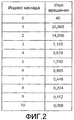
На фиг.2 показаны углы поворота каждой выборки данных согласно настоящему описанию.Figure 2 shows the rotation angles of each data sample according to the present description.
На фиг.3 показан спектр входа и выхода CORDIC передатчика, причем вход является сигналом GSM.Figure 3 shows the input and output spectrum of the CORDIC transmitter, the input being a GSM signal.
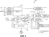
На фиг.4 показана общая блок-схема вращателя согласно настоящему описанию.Figure 4 shows a General block diagram of a rotator according to the present description.
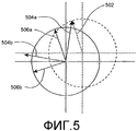
На фиг.5 показана ошибка вследствие вращения I/Q c DC компонентом.5 shows the error due to the rotation of the I / Q c DC component.
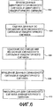
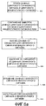
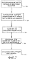
На фиг.6-7 показаны способы коррекции и удаления DC смещения в основанном на НПЧ радиоустройстве.Figures 6-7 show methods for correcting and removing DC bias in an NPC-based radio device.
ОСУЩЕСТВЛЕНИЕ ИЗОБРЕТЕНИЯDETAILED DESCRIPTION OF THE INVENTION
Раскрыт способ коррекции DC смещения в основанном на НПЧ радиоустройстве. Основанное на НПЧ радиоустройство может представлять собой любое коммуникационное устройство, используемое в любой коммуникационной системе. Например, в одном из вариантов осуществления основанное на НПЧ радиоустройство может представлять собой GSM радиоприемник.A method for correcting DC bias in an NPC based radio device is disclosed. An NCH-based radio device can be any communication device used in any communication system. For example, in one embodiment, the NPC-based radio device may be a GSM radio receiver.
В варианте осуществления GSM приемник GSM может использоваться либо с управляемым напряжением кварцевым генератором с температурной компенсаций (VCTCXO) или кварцевым генератором с температурной компенсаций (TCXO); однако, если не используется VCTCXO, требуется вращение для компенсации дрейфа частоты во время работы. Согласно настоящему описанию вращатель комплексной I/Q (синфазной/квадратурной) пары, такой как CORDIC (COordinate Rotation DIgital Computer) вращатель, используется для уменьшения занимаемой площади и сложности вращателя.In an embodiment of the GSM, the GSM receiver can be used either with a voltage controlled temperature compensated crystal oscillator (VCTCXO) or a temperature compensated crystal oscillator (TCXO); however, if VCTCXO is not used, rotation is required to compensate for frequency drift during operation. As described herein, a complex I / Q (common-mode / quadrature) rotator, such as a CORDIC (COordinate Rotation DIgital Computer) rotator, is used to reduce the footprint and complexity of the rotator.
GMSK модулятор производит выбор между потоком I/Q GMSK модулятора и подвергнутым вращению потоком через регистр Modltr_config. Канальный фильтр обеспечивает вращатель 15-битными I/Q данными, предназначенными для вращения в OSR2, и сигналами data_valid, которые указывают на верные данные.The GMSK modulator selects between the I / Q stream of the GMSK modulator and the rotated stream through the Modltr_config register. The channel filter provides the rotator with 15-bit I / Q data intended for rotation in OSR2 and data_valid signals that indicate valid data.
На фиг.1 показана схема прохождения данных от канального фильтра через устройство устранения DC смещения, вращение и обратно в канальный фильтр. Иллюстративная схема включает в себя РЧ 100, соединенную со смесителем 102. Затем выполняется очень грубое удаление DC из сигнала в фильтре 104. Затем антиалиасный фильтр сглаживает края сигнала в 106 и аналого-цифровой преобразователь 108 преобразует аналоговый сигнал в цифровой сигнал и подает сигнал в канальный фильтр 110. Канальный фильтр 110 включает в себя компонент 112 грубого формирования полосы частот. С канальным фильтром 110 соединен вращатель 114. Вращатель 114 включает в себя устройство 116 оценки DC, RAM и арбитр 118, соединенный с компонентом 120 удаления DC смещения. Выход компонента 120 удаления DC смещения соединен с CORDIC вращателем 122. Полученный сигнал данных затем подают в канальный фильтр 124. Данные, принятые от второго каскада канального фильтра, запоминают в локальном RAM или другом запоминающем устройстве, которое расположено в системе вращателя или, в качестве альтернативы, в каком-либо другом месте системы. Система вращателя включает в себя RAM+арбитр, устройство оценки DC, компонент удаления DC смещения и вращатель пары I/Q. В одном из вариантов осуществления на небольшом количестве I/Q пар данных после того, как данные сохранены в локальном RAM, выполняют оценку DC. После выполнения оценки DC данные считывают из RAM и удаляют DC смещение. Затем I/Q пары выборок локализуют и возвращают в канальный фильтр. Компонент грубого удаления DC ограничивает влияние сильных DC смещений на аналого-цифровой преобразователь. Удаление DC смещения может быть определено на фазе калибровки при изготовлении беспроводного устройства, не должно быть динамическим и может быть реализовано, используя простые схемные решения.Figure 1 shows a diagram of the passage of data from a channel filter through a device for eliminating DC bias, rotation and back to the channel filter. The illustrative circuitry includes an
Вращатель I/Q пары работает по итеративному алгоритму, который использует только сдвиги и сложения для вращения вектора. Вращение вектора против часовой стрелки можно представить как:The rotator of the I / Q pair operates on an iterative algorithm that uses only shifts and additions to rotate the vector. The rotation of the vector counterclockwise can be represented as:
Irot+jQrot=(I+JQ)eI(Δ), где Δ представляет собой угол вращенияI rot + jQ rot = (I + JQ) e I (Δ) , where Δ is the angle of rotation
Irot=Icos(Δ)-Qsin(Δ)I rot = Icos (Δ) -Qsin (Δ)
Qrot=Qcos(Δ)+Isin(Δ)Q rot = Qcos (Δ) + Isin (Δ)
После преобразования имеем:After the conversion, we have:
Irot=cos(Δ)(I-Qtg(Δ))I rot = cos (Δ) (I-Qtg (Δ))
Qrot=cos(Δ)(Q-Itg(Δ))Q rot = cos (Δ) (Q-Itg (Δ))
Причем Δ=∑diδ(i), где каждый срез δ(i)=arctg(1/2I) и di=+1 или -1. Такое вращение на любой угол может быть выполнено путем вращения, состоящего из последовательных вращений на фиксированные и меньшие углы. При этом принимают решение добавить или вычесть фиксированный угол. Каждая итерация содержит следующее:Moreover, Δ = ∑d i δ (i), where each slice δ (i) = arctan (1/2 I ) and d i = + 1 or -1. Such rotation at any angle can be performed by rotation consisting of successive rotations at fixed and smaller angles. In this case, they decide to add or subtract a fixed angle. Each iteration contains the following:
Ii+1=Ki(Ii-diQi/2i)I i + 1 = K i (I i -d i Q i / 2 i )
Qi+1=Ki(Qi-diQ/2i)Q i + 1 = K i (Q i -d i Q / 2 i )
Деление на 2i выполняется путем сдвига вправо на i бит или отбрасыванием i младших битов. Таким образом, результат получают при помощи последовательности сдвигов и сложений. Терм Ki представляет собой усиление системы и равно П(1/cos(arctg(1/2I))), для i>5 значение сходится к 1,647.Division by 2 i is performed by shifting to the right by i bits or by dropping the i least significant bits. Thus, the result is obtained using a sequence of shifts and additions. The term K i represents the amplification of the system and is equal to P (1 / cos (arctan (1/2 I ))), for i> 5 the value converges to 1.647.
Угол вращения для каждой выборки данных, как показано на фиг.2, конкретно определяется вращателем I/Q пары.The rotation angle for each data sample, as shown in FIG. 2, is specifically determined by the I / Q pair rotator.
Максимальная фазовая ошибка результата определяется количеством каскадов вращателя. В схеме приемника DC компонент I/Q выборок должен быть удален до вращения. Вращение I/Q пар с DC смещением вызывает как фазовую ошибку, так и ошибку усиления. DC смещение вычисляют путем усреднения по нескольким выборкам. Количество выборок, используемых для этого вычисления, может меняться в зависимости от типа пакета.The maximum phase error of the result is determined by the number of stages of the rotator. In the DC receiver circuitry, the I / Q component of the samples must be removed before rotation. The rotation of the I / Q pairs with DC bias causes both a phase error and a gain error. DC bias is calculated by averaging over several samples. The number of samples used for this calculation may vary depending on the type of packet.
Ячейка вращателя обеспечивает ошибку по частоте в пределах 0,1 ч./млн от частоты несущей базовой станции. Вращатель обеспечивает фазовую ошибку менее чем 0,895 градусов в приемнике и менее чем 0,056 градусов в передатчике. Вращатель выполняет вращение при передаче и при приеме. Вращатель удаляет DC смещение в принятом сигнале и дополнительно описан ниже. Вращатель выполняет вращение цифровых I/Q данных как в приемном, так и в передающем трактах. В настоящем описании поддерживаются режимы GSM/GPRS. Физический вращатель может быть общим для передающего и приемного трактов.The rotator cell provides a frequency error within 0.1 ppm of the carrier base station frequency. The rotator provides a phase error of less than 0.895 degrees in the receiver and less than 0.056 degrees in the transmitter. The rotator rotates during transmission and reception. The rotator removes the DC offset in the received signal and is further described below. The rotator rotates the digital I / Q data in both the receiving and transmitting paths. In the present description, GSM / GPRS modes are supported. The physical rotator may be common to the transmit and receive paths.
Раскрытый способ вносит небольшую задержку в демодуляцию основной полосы. Для типичного принятого пакета необходимо несколько выборок для генерации надежной оценки DC, из которых большинство символов генерируют смещение, а первые символы используются для центровки DC оценки относительно центра пакета. RX пакет прибывает в память DSP в некоторый измеренный момент времени, составляющий Х мкс. Например, в случае принятого пакета длиной 80 символов, в котором все 80 символов требуются для DC оценки, RX пакет прибывает в память DSP с задержкой 16 мкс.The disclosed method introduces a slight delay in the demodulation of the base band. For a typical received packet, several samples are needed to generate a reliable DC estimate, of which most characters generate an offset, and the first characters are used to center the DC estimate relative to the center of the packet. The RX packet arrives in the DSP memory at some measured point in time of X microseconds. For example, in the case of a received packet of 80 characters in length, in which all 80 characters are required for DC estimation, the RX packet arrives in the DSP memory with a delay of 16 μs.
В альтернативном варианте осуществления DC смещение выдается микропроцессором с использованием алгоритма, который усредняет DC смещение для нескольких пакетов. В таком варианте осуществления встроенным ПО вносится очень маленькая задержка.In an alternative embodiment, the DC offset is output by the microprocessor using an algorithm that averages the DC offset for multiple packets. In this embodiment, the firmware introduces a very small delay.
Использование I/Q пары или CORDIC вращателя для компенсации удаления ошибки по частоте, которая является результатом неконтролируемой ХО в GSM передатчике и приемнике, представляет альтернативу DDS вращателя, поскольку вращатель имеет более простую конструкцию и не требует наличия умножителей. При такой конструкции передатчик может иметь каскадный вращатель с аккумулятором битовой фазы, и приемник может иметь каскадный вращатель с аккумулятором битовой фазы.Using an I / Q pair or CORDIC rotator to compensate for the removal of a frequency error that results from uncontrolled XO in the GSM transmitter and receiver represents an alternative to the DDS rotator, since the rotator has a simpler design and does not require multipliers. With this design, the transmitter may have a cascade rotator with a bit phase accumulator, and the receiver may have a cascade rotator with a bit phase accumulator.
Выход аналого-цифрового преобразователя представляет собой, например, 24 выборки, но является достаточным любое количество, превышающее 4. Вращатель введен после прореживания при OSR=2. На выходе частотный отклик является слишком узким для коррекции большого частотного смещения. Частотный отклик до второго прореживания является достаточно широким, так что может быть произведена коррекция, по меньшей мере, для смещения частоты 20 Гц.The output of the analog-to-digital converter is, for example, 24 samples, but any number greater than 4 is sufficient. The rotator is inserted after thinning at OSR = 2. At the output, the frequency response is too narrow to correct a large frequency bias. The frequency response before the second decimation is wide enough so that a correction can be made, at least for a frequency offset of 20 Hz.
В одном из вариантов осуществления, исходя из того, что имеется ограничение на отклонение от частоты несущей базовой станции 0,1 ч./млн и также исходя из того, что частота несущей составляет 900 МГц, получаем, что приемник не должен отклоняться более чем на 90 Гц от частоты базовой станции. Поскольку вращение производят при скорости следования выборок 2 выборки/с или fs=541,67 кГц, 14-битный фазовый аккумулятор имеет достаточное разрешение по частоте, составляющее fs/214=33,1 Гц. Количество каскадов во вращателе, главным образом, определяется величиной фазовой ошибки и искажениями, вносимыми вращателем. Моделирование показало, что семикаскадный вращатель вносит среднеквадратичную фазовую ошибку 0,5 градусов и искажения менее 96 дБ.In one embodiment, based on the fact that there is a limit on the deviation from the carrier frequency of the base station of 0.1 ppm and also on the basis that the carrier frequency is 900 MHz, we see that the receiver should not deviate by more than 90 Hz from the base station frequency. Since rotation is performed at a sampling rate of 2 samples / s or f s = 541.67 kHz, the 14-bit phase accumulator has a sufficient frequency resolution of f s / 2 14 = 33.1 Hz. The number of cascades in the rotator is mainly determined by the magnitude of the phase error and distortion introduced by the rotator. Modeling has shown that a seven-stage rotator introduces a 0.5 degree RMS phase error and less than 96 dB distortion.
На фиг.3 показан спектр входа и выхода CORDIC передатчика, где вход является GSM сигналом, причем видно, что спектр для входа и выхода является практически идентичным.Figure 3 shows the spectrum of the input and output of the CORDIC transmitter, where the input is a GSM signal, and it can be seen that the spectrum for the input and output is almost identical.
Вход вращателя, который является выходом второго фильтра прореживания, имеет разрядность, например, 15 битов. Вращатель обладает определенным коэффициентом усиления, например 1,6468, и, следовательно, увеличивает битовую ширину на один бит. Следовательно, один бит на выходе вращателя удаляют, и оставшиеся 15 битов подаются на оконечный фильтр прореживания. Поскольку вращение выполняется при относительно низкой скорости следования выборок, в виде аппаратных средств необходимо реализовать только один каскад, и одна и та же схема может быть использована для реализации всех каскадов вращения последовательно.The input of the rotator, which is the output of the second decimation filter, has a bit width of, for example, 15 bits. The rotator has a certain gain, for example 1.6468, and therefore increases the bit width by one bit. Therefore, one bit at the output of the rotator is deleted, and the remaining 15 bits are fed to the decimation filter. Since rotation is performed at a relatively low sampling rate, only one cascade needs to be implemented in hardware, and the same circuit can be used to implement all cascades of rotation in series.
Помимо этого, в качестве примера допустим, что скорость следования выборок в передатчике составляет 13 мГц. Следовательно, для того чтобы иметь аналогичное разрешение по частоте, требуется большее количество битов в фазовом аккумуляторе. 19-битный фазовый аккумулятор имеет достаточное разрешение по частоте, составляющее fs/219=24,8 Гц. Количество каскадов во вращателе определяется величиной фазовой ошибки искажениями, вызываемыми вращателем. Моделирование показало, что 11-каскадный вращатель вносит среднеквадратичную фазовую ошибку 0,03 градуса, из которых 0,2 градуса относятся к основной полосе искажения менее 80 дБ.In addition, as an example, let us assume that the sample rate in the transmitter is 13 MHz. Therefore, in order to have a similar frequency resolution, more bits are required in the phase accumulator. The 19-bit phase battery has a sufficient frequency resolution of f s / 2 19 = 24.8 Hz. The number of stages in the rotator is determined by the magnitude of the phase error of the distortions caused by the rotator. The simulation showed that the 11-stage rotator introduces a mean square phase error of 0.03 degrees, of which 0.2 degrees refer to the main distortion band of less than 80 dB.
Схема высокого уровня вращателя 400 показана на фиг.4, и в этом примере вращатель состоит из шести блоков. Интерфейсный регистр 410 позволяет ARM и/или MDSP программировать регистры необходимым образом для вращения и удаления DC смещения. Фазовый аккумулятор 414 включает в себя два фазовых аккумулятора и CORDIC вращатель 416, состоящий из двух отдельных CORDIC вращателей. Дополнительно два отдельных вращателя используются для выполнения вращения. Блок 418 оценки DC и блок 420 удаления DC смещения вычисляют и затем удаляют DC смещение соответственно из входящих I/Q выборок. Блок 422 RAM+арбитр содержит RAM, который используется для хранения I/Q выборок до тех пор, пока не будет вычислено верное DC смещение. RAM+арбитр 422 также управляет потоком данных через схему.A high level diagram of the
Фазовый аккумулятор передатчика выполняет вращение на некоторую величину, выполняя увеличение на phase_offset. Фазовый аккумулятор приемника выполняет вращение каждой верной I/Q пары данных на величину (24)×(phase_offset). Это позволяет программировать один регистр для управления обоими фазовыми аккумуляторами. Программирование phase_offset может быть выполнено MDSP либо ARM. Выбор между двумя возможными командами увеличения фазы управляется ARM. Предполагается, что phase_offset меняется перед каждым вращением и, следовательно, не требуется схемы синхронизации перед регистром phase_offset и фазовым аккумулятором приемника.The transmitter phase battery rotates a certain amount, increasing by phase_offset. The receiver phase battery rotates each valid I / Q data pair by (24) × (phase_offset). This allows you to program one register to control both phase batteries. Phase_offset programming can be done by MDSP or ARM. The choice between the two possible phase increase commands is controlled by ARM. It is assumed that phase_offset changes before each rotation and, therefore, no synchronization circuit is required before the phase_offset register and the receiver phase battery.
Схема удаления DC содержит три элемента, включающих в себя блок 418 оценки DC, блок 420 удаления DC смещения и RAM 422. Блок 418 оценки DC генерирует среднее значение DC для выбранных I/Q выборок до тех пор, пока не будет вычислено верное значение DC. Вращатель приемника удаляет компонент DC из данных перед вращением.The DC removal circuitry contains three elements, including a
На фиг.5 показан пример ошибок, которые могут возникать при вращении I/Q данных с DC компонентом. Вектор 502 DC смещения показан пунктирной линией. В идеальном случае, если DC смещение удалено, I/Q пара 506а и 506b, которая лежит в квадранте 2, будет повернута на 90 градусов и будет перемещена в квадрант 3. Тем не менее, вследствие DC смещения I/Q пары 504а и 504b оказываются в квадранте 1 и в результате вращаются в квадрант 2. Такое вращение также увеличивает переменный коэффициент усиления во время вращения.Figure 5 shows an example of errors that may occur when rotating I / Q data with a DC component. The
Блок оценки DC оценивает среднее входящих выборок, выполняя суммирование отдельных I/Q за определенный пользователем период. Затем блок оценки DC выполняет деление на количество выборок. Период не является фиксированным вследствие различных типов кадров. Пользователь может определить количество выборок для суммирования и определить количество выборок, которое будет пропущено перед началом этапа суммирования. Используется порядок, при котором за суммированием следует этап деления, поскольку схема деления может быть упрощена, если ее необходимо будет использовать один раз за кадр, а не для каждой верной I/Q пары. В случае GPRS при последовательных RX кадрах требуется только одно вычисление DC.The DC estimator estimates the average of the incoming samples by summing individual I / Q over a user-defined period. Then, the DC estimator performs division by the number of samples. The period is not fixed due to different types of frames. The user can determine the number of samples to add and determine the number of samples that will be skipped before the start of the summation phase. The order in which summation is followed by the division stage is used, since the division scheme can be simplified if it will be necessary to use it once per frame, and not for each valid I / Q pair. In the case of GPRS with consecutive RX frames, only one DC calculation is required.
После вычисления смещения DC блок оценки DC запускает RAM+арбитр, который начинает выдавать I/Q данные в блок удаления DC смещения. При этом блок удаления DC смещения вычитает значение DC из входящих I/Q пар данных и передает результат во вращатель. В качестве альтернативного варианта осуществления удаление смещения DC в компонентах вращателя, выполняющих квадратное вращение, объединено для уменьшения требования в логике.After calculating the DC offset, the DC estimator starts the RAM + arbiter, which starts to output I / Q data to the DC offset deletion unit. In this case, the DC bias removal unit subtracts the DC value from the incoming I / Q data pairs and transmits the result to the rotator. As an alternative embodiment, the removal of DC bias in the rotator components performing square rotation is combined to reduce the logic requirement.
На фиг.6 показан иллюстративный способ коррекции DC смещения в НПЧ радиоустройства согласно настоящему описанию. Способ включает в себя этапы приема цифрового синфазного сигнала и цифрового квадратурного сигнала, как показано на этапе 602. Затем выполняют этап оценки DC смещения для синфазного сигнала и квадратурного сигнала, как показано на этапе 604. Затем выполняют этап удаления DC смещения из синфазного сигнала и квадратурного сигнала, как показано на этапе 606. Затем выполняют этап вращения синфазного сигнала и квадратурного сигнала, как показано на этапе 608. Затем необязательно выполняют этап фильтрации для синфазного сигнала и квадратурного сигнала, как показано на этапе 610. В качестве альтернативного варианта осуществления на фиг.6а показан способ коррекции DC смещения в НПЧ радиоустройстве, причем указанный способ является таким же, как и способ, показанный на фиг.6, за исключением этапа 603, на котором выборки данных цифрового синфазного сигнала и цифрового квадратурного сигнала сохраняют в запоминающем устройстве, таком как RAM, перед оценкой DC смещения на этапе 604.FIG. 6 shows an illustrative method for correcting DC bias in an NPF radio device as described herein. The method includes the steps of receiving a digital common-mode signal and a digital quadrature signal, as shown in
На фиг.7 показан способ удаления DC смещения в НПЧ радиоустройстве согласно настоящему описанию. Способ включает в себя этапы преобразования части сигнала в цифровые выборки, как показано на этапе 702. Затем выполняют этап вычисления DC кадра, захватывая весь кадр и часть смежных каналов, как показано на этапе 704. Затем выполняют этап удаления DC смещения из сигнала, как показано на этапе 706. Затем выполняют этап вращения для удаления ошибки по частоте из сигнала, как показано на этапе 708. Затем выполняют этап канальной фильтрации, как показано на этапе 710.7 shows a method of removing DC bias in an NPS radio device as described herein. The method includes the steps of converting part of the signal to digital samples, as shown in
Раскрытые способ и устройство предоставляют решение, обеспечивающее гибкость при приеме демодулированных сигналов от радиоприемника без DC смещения или с относительно малым DC смещением. Это позволяет значительно снизить сложность системы удаления DC смещения НПЧ радиоприемника, поскольку основная часть DC смещения удаляется в цифровом виде, что дает возможность цифровой обработки для удаления DC смещения.The disclosed method and apparatus provides a solution that provides flexibility in receiving demodulated signals from a radio receiver without a DC bias or with a relatively low DC bias. This can significantly reduce the complexity of the system for removing DC bias of the NF radio receiver, since the bulk of the DC bias is digitally removed, which allows digital processing to remove the DC bias.
Приведенное выше описание предоставлено, чтобы дать возможность любому специалисту в данной области техники использовать настоящее изобретение. Различные описания этих вариантов осуществления должны быть очевидны для специалистов в данной области техники, и общие принципы, изложенные в настоящем описании, могут быть использованы в других вариантах осуществления, не подразумевая при этом изобретательской деятельности. Таким образом, настоящее описание не следует ограничивать приведенными в нем вариантами осуществления, но должно соответствовать максимальному объему, совместимому с принципами и новыми отличительными особенностями, изложенными в нем.The above description is provided to enable any person skilled in the art to use the present invention. Various descriptions of these embodiments should be apparent to those skilled in the art, and the general principles set forth herein may be used in other embodiments without implying any inventive activity. Thus, the present description should not be limited to the embodiments presented therein, but should correspond to a maximum amount compatible with the principles and new distinguishing features set forth therein.
Claims (12)
преобразуют часть сигнала в цифровые выборки;
вычисляют DC смещение кадра при помощи захвата целого кадра и части смежных кадров из цифровых выборок;
удаляют DC смещение из по меньшей мере части цифровых выборок;
выполняют вращение для удаления ошибки частоты из по меньшей мере упомянутой части цифровых выборок; и
выполняют канальную фильтрацию для по меньшей мере упомянутой части цифровых выборок.1. A method for removing a constant bias (DC bias) in a radio device based on a zero intermediate frequency (NFC), comprising the steps of:
convert part of the signal to digital samples;
calculating the DC frame offset by capturing the whole frame and a portion of adjacent frames from digital samples;
remove DC bias from at least a portion of the digital samples;
performing rotation to remove the frequency error from at least said portion of the digital samples; and
perform channel filtering for at least the portion of digital samples.
аналого-цифровой преобразователь;
канальный фильтр, соединенный с аналого-цифровым преобразователем;
систему вращателя, соединенную с канальным фильтром;
причем система вращателя содержит:
блок оценки DC, соединенный с промежуточным выходом канального фильтра;
блок удаления смещения DC, соединенный с блоком оценки DC; и
CORDIC вращатель, соединенный с блоком удаления DC смещения, причем выход CORDIC вращателя соединен с частью фильтрации канала канального фильтра.4. An NPH radio device comprising:
analog-to-digital converter;
channel filter connected to an analog-to-digital converter;
a rotator system connected to a channel filter;
moreover, the rotator system contains:
a DC estimator coupled to an intermediate output of the channel filter;
a DC bias removal unit connected to the DC estimator; and
A CORDIC rotator connected to a DC bias removal unit, wherein the CORDIC output of the rotator is connected to a channel filter channel filtering part.
аналого-цифровой преобразователь (АЦП), выполненный с возможностью приема аналоговых данных синфазного и квадратурного сигналов;
запоминающее устройство, соединенное с АЦП и выполненное с возможностью запоминания заданного количества цифровых данных синфазного и квадратурного сигналов;
блок оценки DC смещения, соединенный с АЦП и выполненный с возможностью генерации оцененного DC смещения упомянутых цифровых данных синфазного и квадратурного сигналов;
блок удаления DC смещения, соединенный с блоком оценки DC смещения; и
CORDIC вращатель, соединенный с блоком удаления DC смещения, причем выход CORDIC вращателя соединен с частью фильтрации канала канального фильтра.8. An NPH radio device comprising:
analog-to-digital Converter (ADC), configured to receive analog data in-phase and quadrature signals;
a storage device connected to the ADC and configured to store a predetermined amount of digital data in-phase and quadrature signals;
a DC bias estimator connected to the ADC and configured to generate an estimated DC bias of the digital in-phase and quadrature signals;
a DC bias removal unit connected to the DC bias estimator; and
A CORDIC rotator connected to a DC bias removal unit, wherein the CORDIC output of the rotator is connected to a channel filter channel filtering part.
Applications Claiming Priority (4)
| Application Number | Priority Date | Filing Date | Title |
|---|---|---|---|
| US42122302P | 2002-10-25 | 2002-10-25 | |
| US60/421,223 | 2002-10-25 | ||
| US10/454,395 US6999537B2 (en) | 2002-10-25 | 2003-06-03 | Method of removing DC offset for a ZIF-based GSM radio solution with digital frequency correlation |
| US10/454,395 | 2003-06-03 |
Publications (2)
| Publication Number | Publication Date |
|---|---|
| RU2005115571A RU2005115571A (en) | 2005-11-10 |
| RU2359407C2 true RU2359407C2 (en) | 2009-06-20 |
Family
ID=32110314
Family Applications (1)
| Application Number | Title | Priority Date | Filing Date |
|---|---|---|---|
| RU2005115571/09A RU2359407C2 (en) | 2002-10-25 | 2003-10-27 | Method for elimination of fixed bias for gsm receiver based on zero intermediate frequency with digital correction of frequency bias |
Country Status (7)
| Country | Link |
|---|---|
| US (1) | US6999537B2 (en) |
| EP (1) | EP1554813A1 (en) |
| JP (1) | JP2006504368A (en) |
| AU (1) | AU2003284947A1 (en) |
| CA (1) | CA2502790A1 (en) |
| RU (1) | RU2359407C2 (en) |
| WO (1) | WO2004038939A1 (en) |
Families Citing this family (14)
| Publication number | Priority date | Publication date | Assignee | Title |
|---|---|---|---|---|
| US7068735B2 (en) * | 2003-06-16 | 2006-06-27 | Broadcom Corp. | System and method to perform DC compensation on a radio frequency burst in a cellular wireless network |
| US7583765B2 (en) * | 2005-04-26 | 2009-09-01 | Skyworks Solutions, Inc. | DC offset detection and cancellation in a receiver |
| US8036622B2 (en) * | 2005-09-28 | 2011-10-11 | Qualcomm, Incorporated | DC offset cancellation circuit for a receiver |
| US7986929B2 (en) * | 2006-12-08 | 2011-07-26 | Silicon Laboratories Inc. | Providing channel filtering in an automatic frequency control path |
| US7622987B1 (en) | 2007-01-25 | 2009-11-24 | Pmc-Sierra, Inc. | Pattern-based DC offset correction |
| US11128501B2 (en) * | 2007-07-30 | 2021-09-21 | HuWoMobility, Inc. | Method for fast convergence calibration of radio-frequency transceivers |
| US7929651B1 (en) * | 2007-11-09 | 2011-04-19 | Xilinx, Inc. | Low phase noise recursive direct digital synthesis with automatic gain control gain stabilization |
| KR101462577B1 (en) * | 2007-11-21 | 2014-11-19 | 삼성전자주식회사 | Apparatus and method for removing dc offset in broaband wireless access system |
| WO2013044513A1 (en) * | 2011-09-30 | 2013-04-04 | Motorola Solutions, Inc. | Automatic frequency control methods and apparatus |
| EP2768193B1 (en) * | 2011-11-15 | 2016-04-06 | Huawei Technologies Co., Ltd. | Method and apparatus for correcting in-phase and quadrature signals |
| US8938029B2 (en) * | 2012-08-31 | 2015-01-20 | Vixs Systems, Inc. | DC removal from multicarrier signals |
| US10763977B2 (en) | 2015-03-09 | 2020-09-01 | Sony Corporation | Device and method for determining a DC component |
| CN105553545A (en) * | 2015-12-11 | 2016-05-04 | 中国航空工业集团公司西安航空计算技术研究所 | FC data acquisition and recording instrument recording condition control strategy |
| CN110879402B (en) * | 2019-11-28 | 2021-11-09 | 中国科学院国家空间科学中心 | System and method for eliminating direct current component in GNSS interference measurement of high and medium altitudes |
Family Cites Families (11)
| Publication number | Priority date | Publication date | Assignee | Title |
|---|---|---|---|---|
| KR970002572A (en) * | 1995-06-17 | 1997-01-28 | 김광호 | Method and apparatus for detecting data in data storage devices |
| CN1101091C (en) * | 1996-09-06 | 2003-02-05 | 皇家菲利浦电子有限公司 | A zero-IF receiver |
| JPH11284677A (en) * | 1998-03-27 | 1999-10-15 | Nec Corp | Demodulator and digital radio communication system using it |
| US6504884B1 (en) | 1999-05-12 | 2003-01-07 | Analog Devices, Inc. | Method for correcting DC offsets in a receiver |
| DE19933266A1 (en) | 1999-07-15 | 2000-11-02 | Siemens Ag | Radio signal reception device for mobile communications IC |
| US6868128B1 (en) * | 2000-07-05 | 2005-03-15 | Rfmd Wpan, Inc. | Method and apparatus for calibrating DC-offsets in a direct conversion receiver |
| EP1202445B1 (en) * | 2000-10-30 | 2005-12-14 | Texas Instruments France | Device for cancelling DC-Offsets in a quadrature demodulator, and method |
| IL156857A0 (en) | 2001-01-12 | 2004-02-08 | Qualcomm Inc | Direct conversion digital domain control |
| US7076225B2 (en) | 2001-02-16 | 2006-07-11 | Qualcomm Incorporated | Variable gain selection in direct conversion receiver |
| JP3693963B2 (en) * | 2002-01-30 | 2005-09-14 | 三菱電機株式会社 | Digital demodulation circuit |
| US7130359B2 (en) * | 2002-03-12 | 2006-10-31 | Motorola Inc. | Self calibrating receive path correction system in a receiver |
-
2003
- 2003-06-03 US US10/454,395 patent/US6999537B2/en not_active Expired - Lifetime
- 2003-10-27 RU RU2005115571/09A patent/RU2359407C2/en not_active IP Right Cessation
- 2003-10-27 EP EP03779269A patent/EP1554813A1/en not_active Withdrawn
- 2003-10-27 JP JP2005501687A patent/JP2006504368A/en active Pending
- 2003-10-27 AU AU2003284947A patent/AU2003284947A1/en not_active Abandoned
- 2003-10-27 WO PCT/US2003/033911 patent/WO2004038939A1/en not_active Application Discontinuation
- 2003-10-27 CA CA002502790A patent/CA2502790A1/en not_active Abandoned
Also Published As
| Publication number | Publication date |
|---|---|
| US6999537B2 (en) | 2006-02-14 |
| US20040082302A1 (en) | 2004-04-29 |
| WO2004038939A1 (en) | 2004-05-06 |
| EP1554813A1 (en) | 2005-07-20 |
| CA2502790A1 (en) | 2004-05-06 |
| JP2006504368A (en) | 2006-02-02 |
| AU2003284947A1 (en) | 2004-05-13 |
| RU2005115571A (en) | 2005-11-10 |
Similar Documents
| Publication | Publication Date | Title |
|---|---|---|
| RU2359407C2 (en) | Method for elimination of fixed bias for gsm receiver based on zero intermediate frequency with digital correction of frequency bias | |
| US7676210B2 (en) | Method for performing dual mode image rejection calibration in a receiver | |
| US6459889B1 (en) | DC offset correction loop for radio receiver | |
| US8295371B2 (en) | Multi-carrier receiver for wireless communication | |
| JP3744546B2 (en) | Variable of sampled signal C. Method and apparatus for compensating offset | |
| KR101155801B1 (en) | Low if receiver systems and methods | |
| EP1376967A2 (en) | Digital estimation and correction of I/Q mismatch in direct conversion receivers | |
| KR101233025B1 (en) | Method and system for receiver impairment estimation and correction | |
| JPH10513616A (en) | Digitally compensated direct conversion receiver | |
| US20060183453A1 (en) | Methods and apparatus to perform signal removal in a low intermediate frequency receiver | |
| JP2003509944A (en) | Apparatus and method for compensating direct conversion transceiver interference | |
| US5732111A (en) | Frequency error compensation for direct sequence spread spectrum systems | |
| JP2006050673A (en) | Radio receiver for preloading an average dc-offset into a channel filter | |
| JP2003509909A (en) | Phase interpolation receiver for angle modulated RF signals | |
| EP1568192A1 (en) | Compensating for analog radio component impairments to relax specifications | |
| JP3454882B2 (en) | Wireless receiver | |
| JP2006504368A5 (en) | ||
| US7167535B2 (en) | Circuit sharing for frequency and phase error correction | |
| JP2007513562A (en) | Bandpass sampling receiver and sampling method | |
| JP2000151546A (en) | Ofdm communication apparatus and method | |
| JP2003032313A (en) | Device and method for digital demodulation of signal received in digital communication receiver | |
| JPH0918528A (en) | Control signal detecting method and radio reception device | |
| US20080232498A1 (en) | Radio receiver or transmitter and method for reducing an iq gain imbalance | |
| WO2002017583A2 (en) | Frequency-hopping receiver with clock and carrier recovery | |
| JP2004040678A (en) | Demodulator |
Legal Events
| Date | Code | Title | Description |
|---|---|---|---|
| MM4A | The patent is invalid due to non-payment of fees |
Effective date: 20111028 |