RU2358687C2 - Electrical toothbrush with movable surface for display - Google Patents
Electrical toothbrush with movable surface for display Download PDFInfo
- Publication number
- RU2358687C2 RU2358687C2 RU2006119443/14A RU2006119443A RU2358687C2 RU 2358687 C2 RU2358687 C2 RU 2358687C2 RU 2006119443/14 A RU2006119443/14 A RU 2006119443/14A RU 2006119443 A RU2006119443 A RU 2006119443A RU 2358687 C2 RU2358687 C2 RU 2358687C2
- Authority
- RU
- Russia
- Prior art keywords
- viewing
- electric motor
- gear
- electric
- display
- Prior art date
Links
Images

Classifications
-
- A—HUMAN NECESSITIES
- A61—MEDICAL OR VETERINARY SCIENCE; HYGIENE
- A61C—DENTISTRY; APPARATUS OR METHODS FOR ORAL OR DENTAL HYGIENE
- A61C17/00—Devices for cleaning, polishing, rinsing or drying teeth, teeth cavities or prostheses; Saliva removers; Dental appliances for receiving spittle
- A61C17/16—Power-driven cleaning or polishing devices
- A61C17/22—Power-driven cleaning or polishing devices with brushes, cushions, cups, or the like
- A61C17/225—Handles or details thereof
-
- A—HUMAN NECESSITIES
- A46—BRUSHWARE
- A46B—BRUSHES
- A46B15/00—Other brushes; Brushes with additional arrangements
-
- A—HUMAN NECESSITIES
- A46—BRUSHWARE
- A46B—BRUSHES
- A46B15/00—Other brushes; Brushes with additional arrangements
- A46B15/0087—Brushes with decoration on or in the handle
-
- A—HUMAN NECESSITIES
- A61—MEDICAL OR VETERINARY SCIENCE; HYGIENE
- A61C—DENTISTRY; APPARATUS OR METHODS FOR ORAL OR DENTAL HYGIENE
- A61C17/00—Devices for cleaning, polishing, rinsing or drying teeth, teeth cavities or prostheses; Saliva removers; Dental appliances for receiving spittle
- A61C17/16—Power-driven cleaning or polishing devices
- A61C17/22—Power-driven cleaning or polishing devices with brushes, cushions, cups, or the like
-
- A—HUMAN NECESSITIES
- A63—SPORTS; GAMES; AMUSEMENTS
- A63H—TOYS, e.g. TOPS, DOLLS, HOOPS OR BUILDING BLOCKS
- A63H29/00—Drive mechanisms for toys in general
-
- A—HUMAN NECESSITIES
- A46—BRUSHWARE
- A46B—BRUSHES
- A46B5/00—Brush bodies; Handles integral with brushware
Abstract
Description
Область техники, к которой относится изобретениеFIELD OF THE INVENTION
Изобретение относится к области электрических зубных щеток, а более конкретно, к электрическим зубным щеткам, имеющим движущуюся поверхность для просмотра.The invention relates to the field of electric toothbrushes, and more particularly to electric toothbrushes having a moving surface for viewing.
Предпосылки к созданию изобретенияBACKGROUND OF THE INVENTION
Известны электрические зубные щетки, имеющие один или несколько движущихся держателей для щетинок. Однако желательно было бы также создать и такие электрические зубные щетки, в которых мощность, развиваемая вмонтированным в них миниатюрным электродвигателем, используется для приведения в движение не только соответствующих элементов конструкции, связанных с держателями щетинок, но и, к примеру, таких ее элементов, которые перемещают соответствующую движущуюся поверхность для просмотра, имеющую на себе одно или несколько каких-либо изображений. Указанные движущиеся изображения сделают такую зубную щетку более привлекательной для потребителя, в особенности для ребенка, и будут способствовать проявлению у него повышенного интереса к пользованию такой зубной щеткой.Known electric toothbrushes having one or more moving holders for bristles. However, it would also be desirable to create such electric toothbrushes, in which the power developed by the miniature electric motor mounted in them is used to drive not only the corresponding structural elements associated with the bristle holders, but also, for example, such elements of it that move the corresponding moving surface for viewing, having one or more of any images on it. These moving images will make such a toothbrush more attractive to the consumer, in particular for the child, and will contribute to his increased interest in using such a toothbrush.
Таким образом, задачей настоящего изобретения является повышение привлекательности пользования электрической зубной щеткой за счет обеспечения подвижности нанесенных на конструктивный элемент щетки изображений с возможностью их просмотра.Thus, the objective of the present invention is to increase the attractiveness of using an electric toothbrush by ensuring the mobility of the images applied to the structural element of the brush with the possibility of viewing them.
Краткое изложение существа изобретенияSummary of the invention
Указанная задача решена в электрической зубной щетке, содержащей ручку, внутри которой расположен электродвигатель, головку, имеющую один или несколько подвижных держателей для щетинок, при этом указанный один или несколько держателей для щетинок соединены с электродвигателем, и шейку, расположенную между ручкой и головкой, при этом согласно изобретению в ручке имеется просмотровое окошко и подвижная поверхность для просмотра, расположенная под просмотровым окошком, причем, по меньшей мере, участок указанной поверхности для просмотра виден через просмотровое окошко, при этом указанная поверхность для просмотра связана с электродвигателем так, что вращение вала электродвигателя приводит в движение поверхность для просмотра.This problem is solved in an electric toothbrush containing a handle, inside of which there is an electric motor, a head having one or more movable bristle holders, wherein one or more bristle holders are connected to the electric motor, and a neck located between the handle and the head, with according to the invention, there is a viewing window in the handle and a moving viewing surface located under the viewing window, at least a portion of said viewing surface is visible through the viewing window, while the indicated surface for viewing is connected with the electric motor so that the rotation of the shaft of the electric motor drives the surface for viewing.
Поверхность для просмотра может иметь одно или несколько расположенных на ней изображений.The viewing surface may have one or more images located on it.
Преимущественно поверхность для просмотра закреплена на первой шестерне, соединенной с электродвигателем.Advantageously, the viewing surface is fixed to the first gear connected to the electric motor.
Указанная первая шестерня может находиться в зацеплении со второй шестерней, закрепленной на валу электродвигателя.Said first gear may be engaged with a second gear fixed to the motor shaft.
Кроме того, поверхность для просмотра и электродвигатель могут иметь магнитную связь друг с другом. В этом случае поверхность для просмотра преимущественно закреплена на поворотном диске, который содержит один или несколько ведомых магнитов, на первой шестерне расположены один или несколько ведущих магнитов, при этом первая шестерня соединена с электродвигателем, а между ведущими и ведомыми магнитами образована магнитная связь.In addition, the viewing surface and the motor can be magnetically coupled to each other. In this case, the viewing surface is predominantly fixed to the rotary disk, which contains one or more driven magnets, one or more driving magnets are located on the first gear, while the first gear is connected to the electric motor, and a magnetic coupling is formed between the driving and driven magnets.
При этом первая шестерня в обоих вариантах выполнения связи поверхности для просмотра с электродвигателем может быть соединена со стержнем, который соединен с одним или несколькими держателями для щетинок.In this case, the first gear in both embodiments of the connection surface for viewing with an electric motor can be connected to a rod that is connected to one or more holders for bristles.
Кроме того, электрическая зубная щетка дополнительно содержит выключатель, электрически связанный с электродвигателем и с источником питания так, что при замыкании выключателя включается электродвигатель, приводящий указанную поверхность для просмотра во вращательное движение.In addition, the electric toothbrush further comprises a switch electrically connected to the electric motor and to the power source so that when the switch is closed, the electric motor is turned on, which causes the indicated surface to be rotated.
Такое выполнение электрической зубной щетки позволяет обеспечить подвижность нанесенных на конструктивный элемент щетки изображений с возможностью их просмотра, что способствует повышению привлекательности пользования электрической зубной щеткой.This embodiment of the electric toothbrush allows for the mobility of the images printed on the structural element of the brush with the possibility of viewing them, which increases the attractiveness of using an electric toothbrush.
Краткое описание чертежейBrief Description of the Drawings
Более полное понимание сущности настоящего изобретения будет достигнуто при рассмотрении нижеследующего описания изобретения со ссылками на прилагаемые чертежи, на которых:A more complete understanding of the essence of the present invention will be achieved by considering the following description of the invention with reference to the accompanying drawings, in which:
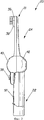
фиг.1 - вид сверху на электрическую зубную щетку, выполненную в соответствии с настоящим изобретением;figure 1 is a top view of an electric toothbrush made in accordance with the present invention;
фиг.2 - вид сбоку на электрическую щетку, изображенную на фиг.1;figure 2 is a side view of the electric brush shown in figure 1;
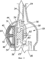
фиг.3 - поперечное сечение зубной щетки, показанной на фиг.1, в увеличенном масштабе;figure 3 is a cross section of the toothbrush shown in figure 1, on an enlarged scale;
фиг.4 - вид сверху на поверхность для просмотра, предусмотренную в зубной щетке, показанной на фиг.1; иfigure 4 is a top view of the surface for viewing provided in the toothbrush shown in figure 1; and
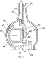
фиг.5 - поперечное сечение в увеличенном масштабе, аналогичное варианту исполнения зубной щетки, показанному на фиг.1, другого варианта осуществления настоящего изобретения.FIG. 5 is an enlarged cross-sectional view similar to the embodiment of the toothbrush shown in FIG. 1 of another embodiment of the present invention.
Подробное описание изобретенияDETAILED DESCRIPTION OF THE INVENTION
Все опубликованные патенты, рассматриваемые в данном описании настоящего изобретения, полностью включаются в данное описание посредством ссылки на них. Далее приводится подробное описание различных вариантов осуществления настоящего изобретения, отдельные примеры которых проиллюстрированы на прилагаемых чертежах, на которых одинаковыми номерами позиций обозначаются одни и те же элементы на всех представленных здесь видах. При этом следует понимать, что настоящее изобретение ориентировано на электрические зубные щетки (включая и электрические зубные щетки, имеющие сменные головки), у который помимо одного или нескольких держателей для щетинок имеется также соответствующая подвижная поверхность для просмотра. Указанная подвижная поверхность для просмотра может иметь непосредственную или же косвенную связь с электродвигателем электрической зубной щетки. Под непосредственной механической связью подразумевается обеспечение соответствующего физического соединения между взаимосвязываемыми элементами (например, при помощи штырьков, клеящих составов, посредством сварки, с помощью стержней, соответствующих крепежных деталей, зубчатых передач и т.д.), а под косвенной механической связью подразумевается обеспечение соответствующего соединения между взаимосвязываемыми элементами без применения при этом каких-либо средств физического соединения, к примеру за счет магнетизма.All published patents discussed in this description of the present invention are fully incorporated into this description by reference to them. The following is a detailed description of various embodiments of the present invention, individual examples of which are illustrated in the accompanying drawings, in which the same reference numerals denote the same elements in all views presented here. It should be understood that the present invention is directed to electric toothbrushes (including electric toothbrushes having replaceable heads), which in addition to one or more bristle holders also has a corresponding movable viewing surface. The specified moving surface for viewing may have a direct or indirect connection with the electric motor of an electric toothbrush. By direct mechanical connection is meant the provision of an appropriate physical connection between interconnected elements (for example, by means of pins, adhesives, by welding, by means of rods, corresponding fasteners, gears, etc.), and by indirect mechanical connection is meant to provide the corresponding connections between interconnected elements without the use of any means of physical connection, for example, due to magnetism.
В приведенном ниже описании со ссылками на фиг.1-4 рассматривается электрическая зубная щетка, изготовленная в соответствии с настоящим изобретением. В предложенной электрической зубной щетке предусматривается наличие стержня, который совершает линейное возвратно-поступательные движение вдоль продольной оси зубной щетки. Несмотря на то, что в данном описании настоящее изобретение будет рассмотрено для большей ясности и простоты на конкретном примере его осуществления в виде устройства, состоящего из миниатюрного электродвигателя и соответствующего стержня, которое проиллюстрировано на фиг.1, тем не менее, следует при этом понимать, что возможны также и различные другие варианты осуществления настоящего изобретения в виде соответствующих устройств, в которых имеются стержень, зубчатая передача и (или) миниатюрный электродвигатель. Например, в описаниях изобретения к заявке США №2003/0163881 и к патентам США №№5617603, 5850603, 5974615, 6032313, 5732432, 5070567, 5170525, 5416942, 3588936, 5867856 и 4397055 рассматриваются разнообразные устройства, в которых имеются стержень, зубчатая передача и (или) электродвигатель, которые могут быть использованы применительно к настоящему изобретению.In the description below, with reference to figures 1-4, an electric toothbrush made in accordance with the present invention is considered. The proposed electric toothbrush provides for the presence of a shaft that performs linear reciprocating motion along the longitudinal axis of the toothbrush. Despite the fact that in this description the present invention will be considered for clarity and simplicity on a specific example of its implementation in the form of a device consisting of a miniature electric motor and a corresponding rod, which is illustrated in figure 1, however, it should be understood that various other embodiments of the present invention are also possible in the form of corresponding devices in which there is a shaft, gear train and (or) miniature electric motor. For example, in the descriptions of the invention to US application No. 2003/0163881 and to US patent No. 5617603, 5850603, 5974615, 6032313, 5732432, 5070567, 5170525, 5416942, 3588936, 5867856 and 4397055 consider a variety of devices in which there is a rod, gear and (or) an electric motor that can be used in relation to the present invention.
Электрическая зубная щетка 20 включает в себя головку 21, корпус или ручку 22 и продолговатую шейку 24, расположенную между ними. Ручка является полой и содержит установленный внутри нее электродвигатель 26 (фиг.3), а также батарейки (не показаны), предназначенные для питания миниатюрного электродвигателя. Электродвигатель обеспечивает вращение его выходного вала 23. Вместо батареек может применяться также подзаряжаемый аккумуляторный источник питания. Стержень 34, по меньшей мере, частично расположен внутри шейки 24 и соединен с одним или несколькими держателями для щетинок. При этом первый подвижный держатель 36 для щетинок размещен на первом конце головки 20, причем указанный первый конец находится в самой передней точке головки 20. Несмотря на то, что первый держатель 36 для щетинок, показанный на приведенных здесь иллюстрациях, имеет круглую форму, тем не менее, могут также использоваться и держатели для щетинок, имеющие какую-нибудь другую форму. Кроме того, несмотря на то, что первый держатель 36 для щетинок показан расположенным на первом конце головки 20, специалистам в данной области техники должно быть понятно, что такой держатель для щетинок может быть расположен и на соответствующем удалении от первого конца головки, а между первым держателем 36 для щетинок и указанным первым концом головки 20 может в этом случае предусматриваться наличие каких-либо иных деталей, к примеру, таких как неподвижные щетинки. Движущийся держатель щетинок 36 и указанный стержень могут быть взаимосвязаны между собой с помощью соответствующих элементов конструкции, известных в данной области техники, к примеру, таких элементов конструкции, которые рассматриваются в описании изобретения к патенту США №6178579. Кроме того, может также предусматриваться наличие второго держателя 38 для щетинок, который располагается непосредственно рядом с первым держателем 36 для щетинок. При этом второй держатель 38 для щетинок может быть также подвижным, как и первый держатель, либо может быть выполнен неподвижным или закрепленным на месте.The
Держатели для щетинок могут совершать различные движения любого вида, в том числе, но, не ограничиваясь только этими видами движения - вращательное, колебательное, возвратно-поступательное, вибрационное, круговое, орбитальное движение, а также совершать эти движения в различных сочетаниях друг с другом. Понятие «вращаться» в контексте настоящего описания изобретения подразумевает угловое движение, совершаемое в одном направлении (например, постоянное движение в направлении по часовой стрелке), тогда как понятие «колебаться» подразумевает вибрационное вращательное движение (например, повторно совершаемые циклы вращательного движения в направлении по часовой стрелке, чередующегося с вращательным движением в направлении против часовой стрелки). Вибрация представляет собой любое периодическое движение, осуществляемое с повторно совершаемыми циклами. Вибрационное движение может совершаться с одной и несколькими частотами и амплитудами. Вибрационное движение, которое, по существу, является линейным, в настоящем описании изобретения определяется как возвратно-поступательное движение. Настоящее изобретение может быть практически реализовано применительно к электрическом зубным щеткам и к головкам для электрических зубных щеток, в которых предусматривается наличие соответствующих стержней, имеющих кинематическую связь с движущимся(-ися) держателем(-ями) головки(-ок), совершающим(-и) вращательное, колебательное, орбитальное или же возвратно-поступательное движение (а также эти же движения в различных сочетаниях друг с другом), сообщая при этом соответствующее движение указанным держателям для щетинок.Holders for bristles can perform various movements of any kind, including, but not limited to these types of movement - rotational, oscillatory, reciprocating, vibrational, circular, orbital movement, and also make these movements in various combinations with each other. The term “rotate” in the context of the present description of the invention means an angular movement in one direction (for example, constant movement in a clockwise direction), while the term “oscillate” means a vibratory rotational movement (for example, repeated cycles of rotational movement in the direction clockwise, alternating with rotational movement in a counterclockwise direction). Vibration is any periodic movement carried out with repeated cycles. Vibrational motion can occur with one or more frequencies and amplitudes. Vibrational motion, which is essentially linear, is defined herein as reciprocating motion. The present invention can be practically implemented with respect to electric toothbrushes and to heads for electric toothbrushes, which provide for the presence of corresponding rods having a kinematic connection with the moving (s) holder (s) of the head (s) making (s) ) rotational, oscillatory, orbital or reciprocating movement (as well as the same movements in various combinations with each other), while communicating the corresponding movement to the specified holders for bristles.
Выключатель 38 электрически связан с батарейками и с электродвигателем 26 и предназначен для замыкания электрической цепи между батарейками и электродвигателем 26, в результате чего электрический ток начинает поступать в электродвигатель. Кроме того, как это известно в данной области техники, электрическая зубная щетка, показанная на фиг.1, может быть также оснащена сменной головкой. Соответствующее устройство, пригодное для использования в настоящем изобретении, раскрыто в описании к патенту США №5617601.The
В ручке 22 имеется просмотровое окошко 40. Просмотровое окошко 40, которое может быть изготовлено из какого-нибудь прозрачного пластического материала, может располагаться в самых разных местах на ручке 22, хотя для большего удобства просмотра потребителем желательно было бы, чтобы такое окошко располагалось над включателем 38, находясь при этом с той же самой стороны ручки, на которой расположен выключатель 38. Несмотря на то, что показанное на рисунке просмотровое окошко 40 имеет круглую форму, тем не менее, могут также быть предусмотрены и другие формы окошка. Ручка 22 может содержать расширенную часть 42, смежную с шейкой 24. Просмотровое окошко 40 может располагаться на или в расширенной части 42. Как показано на фиг.3, расширенная часть 42 может быть выполнена в виде сферы, цилиндра либо иметь какую-нибудь другую изогнутую или криволинейную форму, обеспечивающую возможность размещения внутри нее подвижного колесика, пластинки, диска или иного конструктивного опорного элемента 44, поддерживающего поверхность для просмотра 46. На поверхности 46 для просмотра расположены одно или несколько изображений 48. Под просмотровым окошком 40 находится, по меньшей мере, часть поверхности для просмотра, которая видна через просмотровое окошко 40. При этом просмотровое окошко 40 может иметь самые разные размеры. Однако предпочтительно было бы, чтобы просмотровое окошко 40 имело такой размер, который позволял бы видеть сквозь него одно или несколько изображений, отпечатанных на конструктивном опорном элементе 44. Изображения 48 могут быть выполнены в виде текста, графики, картинок или значков, представленных по отдельности или же в различных сочетаниях друг с другом. Поверхность 46 для просмотра, находящаяся на конструктивном опорном элементе 44, может содержать на себе некоторое множество изображений 48. В одном из вариантов осуществления настоящего изобретения на поверхности 46 для просмотра находятся от 2 до 10 изображений. В другом варианте осуществления настоящего изобретения на поверхности 46 для просмотра находятся от 2 до 6 изображений. При этом предпочтительно было бы, чтобы все эти изображения имели отношение или же были посвящены какой-то одной общей теме, к примеру, такой как спорт. Указанные изображения могут быть посвящены, например, теме футбола и представлять собой рисунки, на которых изображен какой-нибудь футболист. Количество изображений 48 ограничивается только лишь размером поверхности для просмотра, а также размером и местом расположения просмотрового окошка 40. При желании, на ручке или же на расширенной части 42 могут предусматриваться больше, чем одно просмотровое окошко 40. Кроме того, просмотровое окошко 40 может располагаться также и в других местах, а не только в тех местах, которые показаны на прилагаемых чертежах. Помимо этого, просмотровое окошко 40 может быть выполнено также цветным или же тонированным. Для того чтобы потребитель мог с большей легкостью рассматривать изображения, просмотровое окошко также может функционировать и в качестве линзы, обеспечивающей увеличение изображений 48, находящихся на поверхности 46 для просмотра.The
Ниже со ссылками на фиг.3 и 4 описывается предлагаемая электрическая зубная щетка, снабженная соответствующей поверхностью для просмотра, имеющей косвенную связь с электродвигателем 26. Конструктивный опорный элемент 44 может быть выполнен в различных формах, к примеру, в виде пластины, диска, цилиндра и т.д. Как показано на фиг.3, в целях обеспечения лучшего расположения изображений 48 с точки зрения удобства просмотра их потребителем через просмотровое окошко 40, можно установить поверхность 46 для просмотра под некоторым углом. Конструктивный опорный элемент 44 может монтироваться на расширенной части 42 с помощью штырька 50, вмонтированного в саму расширенную часть 42 и в стенку 51. Кроме того, конструктивный опорный элемент 44 может монтироваться на расширенной части 42 также и другими способами, известными в данной области техники. К тому же, несмотря на то, что конструктивный опорный элемент 44 и находящаяся на нем поверхность для просмотра установлены, как показано на прилагаемых чертежах, с обеспечением для них возможности совершать вращательное движение, тем не менее, предполагается, что для конструктивного опорного элемента 44 и (или) для поверхности 46 для просмотра могут быть предусмотрены также и другие виды движения. Например, вместо вращательного движения для конструктивного опорного элемента 44 и (или) для поверхности 46 для просмотра могут предусматриваться колебательное, поступательное или же возвратно-поступательное движение. Более того, может предусматриваться наличие более одного конструктивного опорного элемента или более одной поверхности для просмотра, которые будут совершать точно такое же движение либо совершенно другое движение. Например, одна поверхность для просмотра может совершать движение в направлении по часовой стрелке, в то время как другая поверхность для просмотра может при этом совершать движение в направлении против часовой стрелки. Либо одна поверхность для просмотра может совершать поступательное движение, в то время как другая такая поверхность может при этом вращаться, либо обе поверхности для просмотра могут совершать одинаковое движение (например, обе они могут вращаться в направлении по часовой стрелке).Below, with reference to figures 3 and 4, the proposed electric toothbrush is described, provided with a corresponding viewing surface having an indirect connection with the
На нижней поверхности конструктивного опорного элемента 44 расположены один или несколько ведомых магнитов 54. В одном из вариантов осуществления настоящего изобретения на конструктивном опорном элементе 44 находятся от двух до четырех ведомых магнитов 54. С противоположной стороны относительно ведомых магнитов 54 расположены ведущие магниты 56. Стенка 51 располагается между ведущими и ведомыми магнитами 55 и 54 соответственно. При этом стенка 51 образует собой часть верхнего корпуса 57 ручки 22 зубной щетки и отделяет поверхность 46 для просмотра от электродвигателя 26. При таком обособлении поверхности 46 для просмотра относительно электродвигателя, а также относительно полости 59 обеспечиваются более благоприятные условия для содержания изображений 48 в чистом состоянии и, следовательно, улучшается их видимость. Ведущие магниты 56 закреплены на шестерне 58. Предпочтительно было бы, чтобы ведущие магниты 56 были расположены соосно ведомым магнитам 54 для того, чтобы обеспечивалось наличие соответствующей магнитной связи между ними, благодаря чему при перемещении ведущих магнитов 56 происходило бы соответствующее перемещение ведомых магнитов 54. В варианте осуществления настоящего изобретения, показанном на фиг.3, шестерня 58 вращается вокруг своей оси 62 под воздействием шестерни 60, приводимой во вращение электродвигателем 26. Кроме того, шестерня 58 имеет также кинематическую связь со стержнем 34, предназначенным для передачи движения на держатель 36 для щетинок, приводимый при этом, соответственно, в движение. По мере того, как ведущие магниты 56 совершают вращательное движение вокруг своей оси 62, происходит также и вращательное движение в соответствующем направлении ведомых магнитов 54 вокруг оси 64 штырька 50. В данном варианте осуществления настоящего изобретения оси 62 и 64 располагаются на одной линии друг с другом для обеспечения вращения шестерни 58 и конструктивного опорного элемента 44, по существу, вокруг одной и той же оси. Таким образом, при повороте ведущих магнитов 56 на один оборот конструктивный опорный элемент 44 также совершает один оборот в том же самом направлении за счет магнитного взаимодействия между ведомыми и ведущими магнитами. Несмотря на то, что в варианте осуществления настоящего изобретения, представленном на фиг.3, показано, что ведомые магниты 54 закреплены на нижней поверхности конструктивного опорного элемента 44, следует понимать, что они могут быть закреплены также и на соответствующем отдельном элементе, который, в свою очередь, соединяется с конструктивным опорным элементом 44. Например, ведомые магниты 54 могут быть расположены на второй шестерне (не показана), которая, в свою очередь, соединяется с конструктивным опорным элементом 44, в результате чего шестерня 58 и конструктивный опорный элемент 44 образуют редуктор, имеющий соответствующее передаточное число, в результате чего при повороте шестерни 58 на один оборот в данном случае будет происходить поворот конструктивного опорного элемента 44 больше или меньше, чем на один оборот, в зависимости от конкретного числа зубьев на той и на другой шестерне.One or more
В процессе эксплуатации с помощью включателя 38 замыкают электрическую цепь между электродвигателем 26 и батарейками. При этом электродвигатель приводит во вращение шестерню 60, которая, в свою очередь, вращает шестерню 58. Ведущие магниты 56, вращаемые посредством шестерни 58, в свою очередь, сообщают через ведомые магниты 54 вращение конструктивному опорному элементу 44 и поверхности 46 для просмотра. Как только поверхность для просмотра начинает вращаться, изображения 48 также начинают вращаться и их можно поочередно видеть через просмотровое окошко 40, в котором они друг за другом появляются и исчезают. При выключении потребителем выключателя 38 происходит размыкание электрической цепи между электродвигателем 26 и батарейками, в результате чего электродвигатель 26 прекращает вращать шестерни (т.е. шестерни 60, 62 и 58), конструктивный опорный элемент 44 и поверхность 46 для просмотра. В момент прекращения движения любое из изображений 48, которое оказалось в этом момент под просмотровым окошком 40, будет целиком или частично видно через просмотровое окошко 40, хотя при этом само изображение больше двигаться не будет. Таким образом, при пользовании зубной щеткой будет происходить произвольная смена изображений, которые можно видеть через просмотровое окошко 40, так как поверхность для просмотра каждый раз останавливается в разных позициях под просмотровым окошком 40.In use, the
Несмотря на то, что выше приведены некоторые конкретные варианты осуществления настоящего изобретения, в которых поверхность 46 для просмотра имеет магнитную связь с шестерней 58, тем не менее, следует понимать, что поверхность для просмотра и электродвигатель 26 могут иметь также и непосредственную связь друг с другом. Например, поверхность для просмотра и (или) конструктивный опорный элемент могут крепиться штырьком к шестерне 58, либо поверхность для просмотра может быть выполнена за одно целое с шестерней 58, благодаря чему отпадает необходимость в применении отдельного конструктивного опорного элемента, что и показано в качестве примера на фиг.5. Аналогично, поверхность для просмотра может быть образована на конструктивном опорном элементе, который непосредственно крепится к шестерне 58, к примеру, посредством сварки, клеящих составов и соответствующих соединительных деталей, известных в данной области техники. В этих последних вариантах осуществления настоящего изобретения стенка 51 может быть частично или полностью устранена, а на поверхность для просмотра может быть нанесено защитное покрытие (например, в виде полимерной пленки или мастики) для предотвращения ухудшения качества изображений 48. Кроме того, несмотря на то, что поверхность 46 для просмотра показана расположенной внутри расширенной части ручки, следует понимать, что форма, размер и ориентация поверхности для просмотра могут быть изменены, вследствие чего отпадет необходимость в наличии у ручки указанной расширенной части, как это показано на чертежах.Although the above are some specific embodiments of the present invention, in which the
Настоящее изобретение рассмотрено в приведенном здесь выше описании со ссылками на предпочтительные варианты его осуществления. Очевидно, что при ознакомлении с данным описанием изобретения и пониманием сущности настоящего изобретения специалистами в данной области техники могут быть предложены различные дополнения и изменения, некоторые из которых указаны в настоящем описании. Подразумевается, что все такие дополнения и изменения могут быть в должной мере учтены при условии, что эти изменения и дополнения не выходят за пределы объема и сущности настоящего изобретения, определенные прилагаемой формулой изобретения или же какими-либо иными документами, равнозначными формуле изобретения.The present invention is described in the above description with reference to preferred options for its implementation. Obviously, when reading this description of the invention and understanding the essence of the present invention, specialists in the art can offer various additions and changes, some of which are indicated in the present description. It is understood that all such additions and changes may be duly taken into account, provided that these changes and additions do not go beyond the scope and essence of the present invention defined by the attached claims or by any other documents equivalent to the claims.
Claims (9)
Applications Claiming Priority (2)
| Application Number | Priority Date | Filing Date | Title |
|---|---|---|---|
| US10/701,958 US7007331B2 (en) | 2003-11-05 | 2003-11-05 | Electric toothbrushes having a moving viewing surface |
| US10/701,958 | 2003-11-05 |
Publications (2)
| Publication Number | Publication Date |
|---|---|
| RU2006119443A RU2006119443A (en) | 2007-12-27 |
| RU2358687C2 true RU2358687C2 (en) | 2009-06-20 |
Family
ID=34551549
Family Applications (1)
| Application Number | Title | Priority Date | Filing Date |
|---|---|---|---|
| RU2006119443/14A RU2358687C2 (en) | 2003-11-05 | 2004-11-04 | Electrical toothbrush with movable surface for display |
Country Status (9)
| Country | Link |
|---|---|
| US (1) | US7007331B2 (en) |
| EP (1) | EP1684659B1 (en) |
| JP (1) | JP4746553B2 (en) |
| KR (1) | KR101058705B1 (en) |
| CN (1) | CN1925812B (en) |
| AT (1) | ATE516770T1 (en) |
| CA (1) | CA2544738C (en) |
| RU (1) | RU2358687C2 (en) |
| WO (1) | WO2005046507A1 (en) |
Cited By (3)
| Publication number | Priority date | Publication date | Assignee | Title |
|---|---|---|---|---|
| RU2677829C2 (en) * | 2013-12-30 | 2019-01-21 | Конинклейке Филипс Н.В. | Actuator with grouped magnets for personal care appliance |
| RU2697537C1 (en) * | 2016-09-12 | 2019-08-15 | Конинклейке Филипс Н.В. | Drive assembly for personal hygiene device |
| RU2705619C2 (en) * | 2014-06-17 | 2019-11-11 | Конинклейке Филипс Н.В. | Drive system for individual care device and method for operation thereof |
Families Citing this family (23)
| Publication number | Priority date | Publication date | Assignee | Title |
|---|---|---|---|---|
| US7976388B2 (en) * | 2006-03-24 | 2011-07-12 | Umagination Labs, L.P. | Oral care gaming system with electronic game |
| ES2666363T3 (en) | 2011-05-02 | 2018-05-04 | Water Pik, Inc. | Sonic toothbrush mechanically actuated |
| US9468511B2 (en) | 2013-03-15 | 2016-10-18 | Water Pik, Inc. | Electronic toothbrush with vibration dampening |
| CN107661153B (en) | 2013-03-15 | 2021-01-12 | 洁碧有限公司 | Mechanically driven sonic toothbrush and water dental floss |
| CN205568226U (en) | 2015-07-08 | 2016-09-14 | 洁碧有限公司 | Device of brushing teeth |
| US10561480B2 (en) | 2016-05-09 | 2020-02-18 | Water Pik, Inc. | Load sensing for oral devices |
| USD854329S1 (en) | 2016-11-02 | 2019-07-23 | Dyson Technology Limited | Dental appliance |
| USD836345S1 (en) | 2016-11-02 | 2018-12-25 | Dyson Technology Limited | Handle for dental appliance |
| USD865367S1 (en) * | 2016-11-02 | 2019-11-05 | Dyson Technology Limited | Head for dental appliance |
| CA174300S (en) | 2016-11-02 | 2018-04-18 | Dyson Technology Ltd | Electric toothbrush |
| USD847513S1 (en) * | 2016-11-02 | 2019-05-07 | Dyson Technology Limited | Head for dental appliance |
| USD848747S1 (en) | 2016-11-02 | 2019-05-21 | Dyson Technology Limited | Dental appliance |
| USD848746S1 (en) | 2016-11-02 | 2019-05-21 | Dyson Technology Limited | Dental cleaning appliance |
| USD836346S1 (en) | 2016-11-02 | 2018-12-25 | Dyson Technology Limited | Handle for dental appliance |
| USD854330S1 (en) | 2016-11-02 | 2019-07-23 | Dyson Technology Limited | Dental appliance |
| USD846884S1 (en) * | 2016-11-02 | 2019-04-30 | Dyson Technology Limited | Head for dental appliance |
| JP1595509S (en) | 2016-11-02 | 2018-01-22 | ||
| USD869851S1 (en) | 2016-11-02 | 2019-12-17 | Dyson Technology Limited | Reservoir for dental appliance |
| USD854328S1 (en) | 2016-11-02 | 2019-07-23 | Dyson Technology Limited | Dental appliance |
| JP1595510S (en) | 2016-11-02 | 2018-01-22 | ||
| USD845636S1 (en) | 2016-12-15 | 2019-04-16 | Water Pik, Inc. | Toothbrush handle |
| USD844997S1 (en) | 2016-12-15 | 2019-04-09 | Water Pik, Inc. | Toothbrush handle |
| CN110267622B (en) | 2016-12-15 | 2021-08-13 | 洁碧有限公司 | Scrubbing apparatus with illuminated features |
Family Cites Families (36)
| Publication number | Priority date | Publication date | Assignee | Title |
|---|---|---|---|---|
| US2838976A (en) * | 1956-09-19 | 1958-06-17 | Joseph B Berger | Container with animated display |
| US3006111A (en) * | 1958-06-17 | 1961-10-31 | Koch Fritz | Arrangement in or relating to musical boxes |
| US3168315A (en) * | 1961-07-10 | 1965-02-02 | Alabe Crafts | Amusement device |
| JPS4533470Y1 (en) * | 1968-06-29 | 1970-12-21 | ||
| US3588936A (en) * | 1969-05-13 | 1971-06-29 | John P Duve | Electric toothbrush |
| US4397055A (en) * | 1980-10-20 | 1983-08-09 | Cuchiara Samuel M | Reversable shaft with rotary and selective oscillating motion |
| DE3536048A1 (en) * | 1985-06-21 | 1987-01-02 | Burkhardt & Weber Kg | TOOL CHANGER |
| US4827642A (en) | 1985-08-12 | 1989-05-09 | Chatten Victor H | Drive mechanism |
| US4757986A (en) * | 1986-12-19 | 1988-07-19 | Hwang Shi Geng | Structural improvement of motion type solid water ball |
| JPH0245020A (en) * | 1988-08-08 | 1990-02-15 | Topia Kogyo Kk | Automatic detaching device for tassel for curtain |
| JPH0364129U (en) * | 1989-10-30 | 1991-06-21 | ||
| IL92720A (en) * | 1989-12-15 | 1993-02-21 | Neta Holland | Toothbrush |
| US5170525A (en) * | 1991-05-31 | 1992-12-15 | Giovest Inc. | Battery operated toothbrush |
| IT1261901B (en) * | 1993-02-26 | 1996-06-03 | Ariete Srl | TOOTHBRUSH, ANTI-PLAQUE, MOTORIZED. |
| GB2283411B (en) * | 1993-10-08 | 1997-03-26 | Mcdougall Gregory J | A brush for personal hygiene purposes |
| SE9401319L (en) | 1994-04-19 | 1995-10-20 | Ellemtel Utvecklings Ab | telecommunication systems |
| JPH0819427A (en) * | 1994-07-11 | 1996-01-23 | Seikosha Co Ltd | Electrically driven tooth brush |
| DE4433914A1 (en) * | 1994-09-23 | 1996-03-28 | Braun Ag | Brush part for an electric toothbrush |
| US6032313A (en) * | 1995-05-26 | 2000-03-07 | Tsang; Koon Keung | Household appliance having plural coaxially rotatable or parallel linearly movable heads or tools |
| DE19627752A1 (en) * | 1996-07-10 | 1998-01-15 | Braun Ag | Electric toothbrush |
| US5617603A (en) * | 1996-07-23 | 1997-04-08 | Mei; Tzeng J. N. | Brush head assembly of an electric toothbrush |
| US5732432A (en) * | 1996-11-20 | 1998-03-31 | Addway Engineering Limited | Electric toothbrushes |
| US6178579B1 (en) * | 1998-09-30 | 2001-01-30 | Dr. Johns Products, Ltd. | Electric toothbrush |
| US6202242B1 (en) * | 1999-01-29 | 2001-03-20 | Zephyr Design, Inc. | Light emitting electric toothbrush |
| US6183336B1 (en) * | 1999-05-26 | 2001-02-06 | Thomas J. Coleman | Tornado pop |
| US6850167B2 (en) * | 1999-12-08 | 2005-02-01 | Howard Rosen | Brushing behavior reinforcement toothbrush and enclosed electronic game switch with grid |
| JP2001356725A (en) * | 2000-06-12 | 2001-12-26 | Touyou Nissoo Kogei Kk | Display device |
| KR100434752B1 (en) * | 2000-11-29 | 2004-06-14 | 윤승룡 | Photovoltaic Ion Toothbrush with Light Emitter |
| CN2452462Y (en) * | 2000-12-08 | 2001-10-10 | 刘平 | Double head and rotating electric tooth-brush |
| US20030017874A1 (en) * | 2001-07-23 | 2003-01-23 | Ye Jianfei | Toothbrush with electronic-game apparatus |
| DE10209320A1 (en) * | 2002-03-02 | 2003-09-25 | Braun Gmbh | Toothbrush head of an electric toothbrush |
| US20030166373A1 (en) * | 2002-03-04 | 2003-09-04 | The Procter & Gamble Co. | Toothbrush kit |
| US20030183241A1 (en) * | 2002-04-01 | 2003-10-02 | James Kemp | Toothbrush assembly |
| US20040187889A1 (en) * | 2002-04-01 | 2004-09-30 | Colgate-Palmolive Company | Toothbrush assembly |
| WO2004024016A2 (en) | 2002-09-10 | 2004-03-25 | Colgate-Palmolive Company | Toothbrush with transparent handle |
| US20030019063A1 (en) * | 2002-09-26 | 2003-01-30 | Homedics, Inc. | Picture display toothbrush |
-
2003
- 2003-11-05 US US10/701,958 patent/US7007331B2/en not_active Expired - Lifetime
-
2004
- 2004-11-04 JP JP2006538519A patent/JP4746553B2/en not_active Expired - Fee Related
- 2004-11-04 RU RU2006119443/14A patent/RU2358687C2/en not_active IP Right Cessation
- 2004-11-04 WO PCT/US2004/036986 patent/WO2005046507A1/en active Application Filing
- 2004-11-04 AT AT04800813T patent/ATE516770T1/en not_active IP Right Cessation
- 2004-11-04 CN CN200480035829XA patent/CN1925812B/en not_active Expired - Fee Related
- 2004-11-04 KR KR1020067010633A patent/KR101058705B1/en not_active IP Right Cessation
- 2004-11-04 EP EP04800813A patent/EP1684659B1/en not_active Not-in-force
- 2004-11-04 CA CA2544738A patent/CA2544738C/en not_active Expired - Fee Related
Cited By (3)
| Publication number | Priority date | Publication date | Assignee | Title |
|---|---|---|---|---|
| RU2677829C2 (en) * | 2013-12-30 | 2019-01-21 | Конинклейке Филипс Н.В. | Actuator with grouped magnets for personal care appliance |
| RU2705619C2 (en) * | 2014-06-17 | 2019-11-11 | Конинклейке Филипс Н.В. | Drive system for individual care device and method for operation thereof |
| RU2697537C1 (en) * | 2016-09-12 | 2019-08-15 | Конинклейке Филипс Н.В. | Drive assembly for personal hygiene device |
Also Published As
| Publication number | Publication date |
|---|---|
| WO2005046507A1 (en) | 2005-05-26 |
| JP2007510472A (en) | 2007-04-26 |
| ATE516770T1 (en) | 2011-08-15 |
| CN1925812B (en) | 2010-12-15 |
| EP1684659A1 (en) | 2006-08-02 |
| KR20070023635A (en) | 2007-02-28 |
| CA2544738A1 (en) | 2005-05-26 |
| RU2006119443A (en) | 2007-12-27 |
| CN1925812A (en) | 2007-03-07 |
| JP4746553B2 (en) | 2011-08-10 |
| US7007331B2 (en) | 2006-03-07 |
| EP1684659B1 (en) | 2011-07-20 |
| CA2544738C (en) | 2013-02-19 |
| KR101058705B1 (en) | 2011-08-22 |
| US20050091768A1 (en) | 2005-05-05 |
Similar Documents
| Publication | Publication Date | Title |
|---|---|---|
| RU2358687C2 (en) | Electrical toothbrush with movable surface for display | |
| ES2761286T3 (en) | Personal hygiene device | |
| RU2350299C2 (en) | Electric toothbrush | |
| US9154025B2 (en) | Personal care device | |
| RU2433800C2 (en) | Cleaning section for electric toothbrush | |
| KR101445948B1 (en) | Brush section for an electric toothbrush | |
| JP2007510472A5 (en) | ||
| KR20050056917A (en) | Complex motion toothbrush | |
| MXPA03000179A (en) | Powered toothbrush having three dimensional rotational head motion. | |
| JP2005503888A (en) | Electric toothbrush with at least one brush head | |
| CN102186435A (en) | Brush mechanism | |
| CN102429739A (en) | Electric toothbrush | |
| MXPA06006952A (en) | Electric toothbrush. | |
| EP1011514A1 (en) | Mechanical toothbrush | |
| CN202446287U (en) | Electric toothbrush | |
| KR101066646B1 (en) | Electric Toothbrush | |
| JPH05146314A (en) | Electrically driven tooth brush | |
| JPH0838256A (en) | Automatic tooth brushing device | |
| US7331076B2 (en) | Electric tooth brush with a latitudely oscillating brush head | |
| CN210019755U (en) | High-efficient clear magnetism electric toothbrush | |
| MXPA06005114A (en) | Electric toothbrushes having a moving viewing surface | |
| KR102089377B1 (en) | Vibrating device for toothbrush | |
| CN100413479C (en) | Electric toothbrush | |
| CN2443708Y (en) | Multifunctional electric magnet therapy vibrating toothbrush | |
| JP2603753Y2 (en) | electric toothbrush |
Legal Events
| Date | Code | Title | Description |
|---|---|---|---|
| MM4A | The patent is invalid due to non-payment of fees |
Effective date: 20101105 |