RU2354103C1 - Handler for well-ordered packing of large square bale of plant material - Google Patents
Handler for well-ordered packing of large square bale of plant material Download PDFInfo
- Publication number
- RU2354103C1 RU2354103C1 RU2007147311/12A RU2007147311A RU2354103C1 RU 2354103 C1 RU2354103 C1 RU 2354103C1 RU 2007147311/12 A RU2007147311/12 A RU 2007147311/12A RU 2007147311 A RU2007147311 A RU 2007147311A RU 2354103 C1 RU2354103 C1 RU 2354103C1
- Authority
- RU
- Russia
- Prior art keywords
- bale
- tray
- contact sensor
- guides
- unloading
- Prior art date
Links
- 239000000463 material Substances 0.000 title claims description 5
- 238000012856 packing Methods 0.000 title abstract description 3
- 239000000126 substance Substances 0.000 abstract 1
- 230000007246 mechanism Effects 0.000 description 6
- 238000010586 diagram Methods 0.000 description 4
- 230000005484 gravity Effects 0.000 description 4
- 239000002689 soil Substances 0.000 description 3
- 238000003306 harvesting Methods 0.000 description 2
- 238000005516 engineering process Methods 0.000 description 1
- 239000012530 fluid Substances 0.000 description 1
- 230000007935 neutral effect Effects 0.000 description 1
- 238000007665 sagging Methods 0.000 description 1
Images
Landscapes
- Loading Or Unloading Of Vehicles (AREA)
Abstract
Description
Изобретение относится к механизации сельского хозяйства, а именно к устройствам, транспортирующим крупногабаритные прямоугольные тюки растительных материалов.The invention relates to the mechanization of agriculture, and in particular to devices transporting large rectangular bales of plant materials.
Известно транспортирующее устройство SCHWAD (см. «Top agrar», 2002. № 1 стр.108.) для сдваивания тюков, сформированных пресс-подборщиком с целью повышения производительности погрузочных работ.The SCHWAD conveying device is known (see "Top agrar", 2002. No. 1 p. 108.) for doubling bales formed by the baler in order to increase the productivity of loading operations.
Устройство содержит кронштейны, которыми крепят непосредственно за пресс-подборщиком сварную П-образную раму на пневматических колесах, состоящую из вертикальных стоек и горизонтальной перемычки. К вертикальным стойкам П-образной рамы шарнирно крепятся два вилочных захвата, содержащие по три дугообразных пальца и гидроцилиндр привода. На верхней перемычке расположены гидрораспределитель и соединенный с ним контактный датчик. Привод гидроцилиндров осуществляется по гидрошлангам от гидросистемы трактора.The device contains brackets that attach a welded U-shaped frame on pneumatic wheels directly behind the baler, consisting of vertical struts and a horizontal jumper. Two forks containing three arched fingers and a drive hydraulic cylinder are hinged to the vertical posts of the U-shaped frame. On the upper jumper are a control valve and a contact sensor connected to it. The hydraulic cylinders are driven by hydraulic hoses from the tractor hydraulic system.
Работа транспортирующего устройства заключается в следующем. После формирования тюк выходит из прессовальной камеры пресс-подборщика и воздействует на контактный датчик. Гидрораспределитель подает рабочую жидкость в гидроцилиндры на вилочных захватах, происходит их поворот в шарнирах, и дугообразные пальцы внедряются в тюк. После внедрения движение штоков гидроцилиндров продолжается и тюк приподнимается на некоторую высоту над поверхностью поля и транспортируется до момента формирования следующего тюка. В результате тюки укладываются на поле по парам.The operation of the conveying device is as follows. After forming, the bale leaves the baler chamber and acts on the contact sensor. The hydraulic distributor delivers the working fluid to the hydraulic cylinders on the forks, they rotate in the hinges, and the arcuate fingers are embedded in the bale. After introduction, the movement of the hydraulic cylinder rods continues and the bale rises to a certain height above the field surface and is transported until the next bale is formed. As a result, the bales are stacked on the field in pairs.
Основными недостатками аналога является то, что внедрение дугообразных пальцев и небольшая высота подъема тюка над поверхностью поля могут привести к повреждению формы тюка или обвязочного материала (шпагата) при транспортировании.The main disadvantages of the analogue are that the introduction of arched fingers and the small height of the bale lifting above the field surface can lead to damage to the shape of the bale or strapping material (twine) during transportation.
Прототипом предлагаемого транспортирующего устройства для упорядоченной укладки крупногабаритных прямоугольных тюков является устройство для транспортировки и сдваивания тюков (см. Проспект фирмы «CLAAS» с.3, 4, 9, 14. или http://www.claas.com/countries/senerator/clpw/ru/products/pr/quadrant-1150/start, lang=ru GUS_html).The prototype of the proposed transporting device for the orderly packing of large rectangular bales is a device for transporting and doubling bales (see CLAAS brochure p.3, 4, 9, 14. or http://www.claas.com/countries/senerator/ clpw / ru / products / pr / quadrant-1150 / start, lang = ru GUS_html).
Устройство состоит из несущей сварной рамы с закрепленными на ней самоустанавливающимися пневматическими колесами, приемным лотком и кронштейнами крепления к пресс-подборщику, шарнирно закрепленного выгрузного лотка и направляющих, возвратных пружин и сложной конструкции системы тяг и механизмов с помощью которых осуществляется работа устройства, контактного датчика, передающего воздействие через систему тяг и механизмов на запорные устройства направляющих и выгрузного лотка, а также из механизма схода третьего тюка.The device consists of a welded support frame with self-mounted pneumatic wheels fixed on it, a receiving tray and mounting brackets to the baler, a pivotally mounted unloading tray and guides, return springs and a complex design of the rod system and mechanisms with which the device, contact sensor, transmitting the impact through the system of rods and mechanisms to the locking devices of the guides and the discharge tray, as well as from the vanishing mechanism of the third bale.
Данное устройство работает следующим образом. Сформированный тюк выходит из прессовальной камеры пресс-подборщика и попадает на приемный лоток и затем на направляющие, по которым движется в продольном направлении за счет напорного действия следующего тюка. Движение тюка по направляющим продолжается до воздействия на контактный датчик, который через систему тяг и механизмов раздвигает направляющие, и тюк под действием силы тяжести опускается между направляющими на выгрузной лоток. Воздействие на контактный датчик прекращается, и направляющие возвращаются в исходное положение. Следующий тюк также попадает на приемный лоток и направляющие, движется до воздействия на контактный датчик, после чего направляющие раздвигаются и он укладывается на первый тюк, а поскольку его продольное движение не прекращается, он продолжает воздействовать на контактный датчик, который переходит в крайнее положение и через систему тяг открывает запорное устройство выгрузного лотка. После этого лоток поворачивается до соприкосания с поверхностью поля и два уложенных друг на друга тюка за счет силы сцепления с почвой сползают на поверхность поля. Воздействие на контактный датчик прекращается, направляющие и выгрузной лоток под действием пружин возвращаются в первоначальное положение. Таким образом устройство производит несвязанные паковки по два тюка и выгружает их на поверхность поля в автоматическом режиме.This device operates as follows. The formed bale leaves the press chamber of the baler and enters the receiving tray and then onto the guides along which it moves in the longitudinal direction due to the pressure action of the next bale. The movement of the bale along the guides continues until it acts on the contact sensor, which pushes the guides through the system of rods and mechanisms, and the bale falls under the influence of gravity between the guides on the unloading tray. The action on the contact sensor is terminated, and the guides return to their original position. The next bale also falls on the receiving tray and the guides, moves until it acts on the contact sensor, after which the guides slide apart and it fits on the first bale, and since its longitudinal movement does not stop, it continues to act on the contact sensor, which goes to the extreme position and through the linkage system is opened by the discharge tray locking device. After this, the tray rotates until it contacts the surface of the field and two bales stacked on top of one another slide to the field surface due to the force of adhesion to the soil. The impact on the contact sensor is terminated, the guides and the unloading tray under the action of springs are returned to their original position. Thus, the device produces unbound packages of two bales and unloads them on the field surface in automatic mode.
Основными недостатками данного устройства являются:The main disadvantages of this device are:
1. Отсутствие возможности выполнять сброс тюков по требованию оператора и упорядочение укладывать их на поверхности поля.1. The inability to discharge bales at the request of the operator and ordering to lay them on the field surface.
2. Сложная конструкция механической системы датчиков и тяг.2. The complex design of the mechanical system of sensors and rods.
3. Конструкция выгрузного лотка не позволяет быстро и точно укладывать тюки на поле.3. The design of the discharge tray does not allow you to quickly and accurately stack bales on the field.
4. Выгрузной лоток во время выгрузки тюка длительное время соприкасается с почвой, что приводит к его ускоренному выходу из строя.4. The unloading tray during unloading of the bale for a long time comes into contact with the soil, which leads to its accelerated failure.
Технической задачей предлагаемого изобретения является обеспечение возможности выполнять сброс тюков по требованию оператора и упорядоченно укладывать их на поверхности поля без применения сложной механической системы датчиков и тяг, а также выполнять быструю и точную выгрузку тюка на поле без контакта выгрузного лотка с почвой.The technical task of the invention is to provide the ability to discharge bales at the request of the operator and to lay them orderly on the surface of the field without the use of a complex mechanical system of sensors and rods, as well as to perform fast and accurate unloading of the bale on the field without contact of the discharge tray with the soil.
Решение технической задачи достигается в транспортирующем устройстве для упорядоченной укладки крупногабаритных прямоугольных тюков растительных материалов, содержащем несущую раму с закрепленными на ней самоустанавливающимися пневматическими колесами, приемный лоток и кронштейны крепления к пресс-подборщику, шарнирно закрепленные на раме направляющие и выгрузной лоток, а также контактный датчик, расположенный в задней части рамы, где согласно изобретению устройство снабжено тремя запорными устройствами с электротяговыми реле, одно из которых фиксирует направляющие, а два других расположены в месте фиксации выгрузного лотка, при этом электротяговые реле запорных устройств соединены электрической цепью с контактным датчиком, а также с сигнальной лампочкой и кнопкой принудительной выгрузки на приборном щитке трактора, кроме того, длина выгрузного лотка составляет три четвертых длины тюка.The solution to the technical problem is achieved in a transporting device for the orderly laying of large-sized rectangular bales of plant materials, containing a supporting frame with self-mounted pneumatic wheels fixed to it, a receiving tray and mounting brackets to the baler, guides and an unloading tray articulated on the frame, as well as a contact sensor located in the rear of the frame, where, according to the invention, the device is equipped with three locking devices with electric traction relays, o the bottom of which fixes the guides, and the other two are located in the place of fixation of the discharge tray, while the electric traction relays of the locking devices are connected by an electric circuit to the contact sensor, as well as to the signal lamp and the forced discharge button on the tractor dashboard, in addition, the length of the discharge tray is three fourth of the length of the bale.
Предлагаемое изобретение отличается от прототипа тем, что снабжено тремя запорными устройствами с электротяговыми реле, одно из которых фиксирует направляющие, а два других расположены в месте фиксации выгрузного лотка, при этом электротяговые реле запорных устройств соединены электрической цепью с контактным датчиком, а также с сигнальной лампочкой и кнопкой принудительной выгрузки на приборном щитке трактора, кроме того, длина выгрузного лотка составляет три четвертых длины тюка. Таким образом в отличие от прототипа запорные устройства выполнены с применением электротяговых реле, это позволяет использовать электрические цепи вместо сложных механизмов и тяг. Контактный датчик выполнен в виде электрического ключа, замыкающего электрическую цепь, связывающую электротяговые реле запорных устройств, сигнальную лампочку и кнопку принудительной выгрузки на приборном щитке трактора. Длина выгрузного лотка уменьшена и составляет три четвертых длины тюка, что позволяет осуществить быструю и точную укладку тюков на поверхность поля. Такая длина обеспечивает незначительное провисание тюка, что предотвращает его повреждение, а также обеспечивает надежное зацепление тюка со стерней поля, при этом лоток не касается поверхности поля. Предлагаемая конструкция позволяет надежно захватывать тюки, транспортировать и укладывать их сдвоенными в автоматическом режиме или благодаря наличию сигнальной лампочки и кнопки принудительной выгрузки укладывать их упорядоченно в ровные ряды на поверхности поля. При этом сокращается время выгрузки тюков и увеличивается ее точность.The present invention differs from the prototype in that it is equipped with three locking devices with electric traction relays, one of which fixes the guides, and the other two are located in the place where the discharge tray is fixed, while the electric traction relays of the locking devices are connected by an electric circuit to a contact sensor, as well as to a signal lamp and the button of forced unloading on the dashboard of the tractor, in addition, the length of the unloading tray is three quarters of the length of the bale. Thus, in contrast to the prototype, locking devices are made using electric traction relays, this allows the use of electrical circuits instead of complex mechanisms and rods. The contact sensor is made in the form of an electric key that closes the electric circuit that connects the electric traction relays of the locking devices, a signal light and a forced unloading button on the tractor dashboard. The length of the unloading tray is reduced to three quarters of the length of the bale, which allows for fast and accurate stacking of bales on the field surface. This length provides slight sagging of the bale, which prevents damage to the bale, and also provides reliable engagement of the bale with the field stub, while the tray does not touch the field surface. The proposed design allows you to reliably grab the bales, transport and stack them double in automatic mode or, thanks to the presence of a signal light and a forced unloading button, stack them orderly in even rows on the field surface. This reduces the time of unloading bales and increases its accuracy.
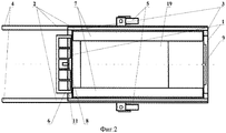
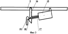
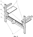
На фиг.1 изображена схема транспортирующего устройства в прямоугольной проекции, вид сбоку; на фиг.2 изображена схема транспортирующего устройства в прямоугольной проекции, вид сверху; на фиг.3 изображена схема запорного устройства выгрузного лотка; на фиг.4 - схема запорного устройства направляющих.Figure 1 shows a diagram of a conveying device in a rectangular projection, side view; figure 2 shows a diagram of a conveying device in a rectangular projection, top view; figure 3 shows a diagram of the locking device of the discharge tray; figure 4 - diagram of the locking device of the guides.
Транспортирующее устройство состоит из сварной несущей рамы, представляющей собой прямоугольную пространственную конструкцию, содержащую: три поперечные балки 1 (фиг.1, 2); четыре продольные балки 2, две из которых нижние; четыре вертикальные стойки 3; кронштейнов крепления 4 к пресс-подборщику; и самоустанавливающихся колес 5. К двум вертикальным стойкам 3, расположенным в передней части несущей рамы, жестко крепится приемный лоток 6, служащий для приема и подачи тюка на направляющие 7. Направляющие 7 шарнирно крепятся ко всем четырем вертикальным стойкам 3 и снабжены возвратными пружинами 10, которыми направляющие 7 возвращаются в рабочее положение и удерживаются запорным устройством 8 с электротяговым реле 11. Контактный датчик 9 шарнирно закреплен на задней поперечной балке 1 и имеет три положения: первоначальное (нейтральное), когда электрические цепи разомкнуты, среднее, при котором замыкается цепь запорного устройства 8 направляющих 7 и загорается сигнальная лампочка (не показана) на приборном щитке трактора, и крайнее, при котором замыкается цепь запорных устройств 14 выгрузного лотка 19. Запорное устройство 8 с электротяговым реле 11 (фиг.4) расположено на передней поперечной балке 1 несущей рамы и представляет собой двухрычажное устройство, где оба рычага 12 жестко соединены между собой перемычкой 13. Каждый из рычагов 12 одним концом шарнирно соединен с верхней поперечной балкой 1 несущей рамы, а другой конец фиксирует направляющие 7. На каждой продольной нижней балке 2 расположены два запорных устройства 14, представляющие собой одно рычажную систему с электротяговым реле 15 (фиг.3), где рычаг 16 одним концом шарнирно соединен с нижней балкой 2, а другим концом, где у него находится язычок 18, который фиксирует выгрузной лоток 19, шарнирно соединен со штоком 17 тягового реле 15. При этом электротяговое реле 15 связано электрической цепью с кнопкой принудительной выгрузки (не показана) на приборном щитке трактора для освобождения выгрузного лотка 19. Выгрузной лоток, имеющий длину три четвертых длины тюка, шарнирами 20 (фиг.1) соединен с передней вертикальной стойкой 3 и ограничен в повороте упором 21 для того, чтобы выгрузной лоток 19 не касался поверхности поля при выгрузке тюка. В исходное положение выгрузной лоток возвращается при помощи возвратных пружин 22.The conveying device consists of a welded supporting frame, which is a rectangular spatial structure, comprising: three transverse beams 1 (1, 2); four
Устройство работает следующим образом. При выходе из прессованной камеры пресс-подборщика приемный лоток 6 плавно направляет тюк чуть выше направляющих 7, что обеспечивает дальнейшее беспрепятственное прохождение тюка. Тюк перемещается по направляющим 7 до воздействия на контактный датчик 9. После его перевода в среднее положение замыкается цепь электротягового реле 11, входящего в запорное устройство 8, которое освобождает направляющие 7, и тюк под действием силы тяжести перемещается на выгрузной лоток 19. При этом загорается сигнальная лампочка на приборном щитке трактора. Воздействие на контактный датчик 9 прекращается, и электрическая цепь прерывается, под воздействием пружин 10 направляющие 7 возвращаются в исходное положение и фиксируются запорным устройством 8. Следующий тюк, аналогично первому, перемещаясь по направляющим 7, через некоторое время начинает воздействовать на контактный датчик 9. При этом за время движения второго тюка по направляющим 7 первый тюк просто транспортируется и находится в ожидании выгрузки по команде оператора посредством нажатия кнопки принудительной выгрузки на приборном щитке трактора. Нажатая кнопка замыкает цепь, и электрический ток подается на электротяговые реле 15 запирающих устройств 14, которые освобождают выгрузной лоток 19. Выгрузной лоток с тюком поворачивается на шарнирах 20 (фиг.2) под действием силы тяжести, и тюк укладывается на поверхность поля, а так как лоток имеет длину три четвертых длины тюка, его сход осуществляется более точно и быстро. Таким образом, осуществляется упорядоченная укладка тюков в ряды на поверхности поля.The device operates as follows. When leaving the pressed chamber of the baler, the receiving
Если же оператор не осуществляет принудительную выгрузку тюка, то второй тюк после воздействия на контактный датчик укладывается на первый, а так как на него воздействует третий тюк, идущий за ним, он продолжает воздействие на контактный датчик 9, который при определенном усилии переходит в крайнее положение и замыкает вторую цепь электротяговых реле 15, запорных устройств 14 (фиг.2) выгрузного лотка 19. Тюки под действием силы тяжести поворачивают лоток 19 и сходят на поверхность поля уложенными друг на друга. После схода тюков лоток 19 за счет пружин 22 (фиг.2) возвращается в исходное положение, а запорные устройства 14 фиксируют его положение.If the operator does not carry out forced unloading of the bale, then the second bale, after acting on the contact sensor, is placed on the first one, and since the third bale coming after it acts on it, it continues to influence the
Такая конструкция обеспечивает надежный захват тюков без его повреждения, их транспортировку и возможность укладывать тюки по требованию оператора, упорядочение на поверхности поля, так и сдвоенными в автоматическом режиме. При этом в устройстве отсутствуют сложные механизмы, а укороченный выгрузной лоток обеспечивает быстрое и точное освобождение тюков и не контактирует с поверхностью поля.This design provides reliable grip of bales without damaging them, their transportation and the ability to stack bales at the request of the operator, ordering on the field surface, and doubled in automatic mode. At the same time, the device lacks complex mechanisms, and a shortened unloading tray provides quick and accurate release of bales and does not come into contact with the field surface.
Применение данного транспортирующего устройства позволит как сдваивать тюки в несвязанные паковки на поле, так и упорядоченно укладывать их в ровные ряды на поверхности поля.The use of this transporting device will allow you to double bales into unconnected packages on the field, and orderly stack them in even rows on the field surface.
Устройство расширяет возможности уборочной технологии, обеспечивает сокращение переездов погрузочных агрегатов при уборке тюков, сокращение затрат на ТСМ, сокращение площади уплотненной поверхности поля и значительно увеличивает производительность погрузочно-транспортных работ.The device expands the possibilities of harvesting technology, provides a reduction in the movement of loading aggregates when harvesting bales, a reduction in the cost of FCM, a reduction in the area of the compacted surface of the field, and significantly increases the productivity of handling operations.
Claims (1)
Priority Applications (1)
| Application Number | Priority Date | Filing Date | Title |
|---|---|---|---|
| RU2007147311/12A RU2354103C1 (en) | 2007-12-18 | 2007-12-18 | Handler for well-ordered packing of large square bale of plant material |
Applications Claiming Priority (1)
| Application Number | Priority Date | Filing Date | Title |
|---|---|---|---|
| RU2007147311/12A RU2354103C1 (en) | 2007-12-18 | 2007-12-18 | Handler for well-ordered packing of large square bale of plant material |
Publications (1)
| Publication Number | Publication Date |
|---|---|
| RU2354103C1 true RU2354103C1 (en) | 2009-05-10 |
Family
ID=41019645
Family Applications (1)
| Application Number | Title | Priority Date | Filing Date |
|---|---|---|---|
| RU2007147311/12A RU2354103C1 (en) | 2007-12-18 | 2007-12-18 | Handler for well-ordered packing of large square bale of plant material |
Country Status (1)
| Country | Link |
|---|---|
| RU (1) | RU2354103C1 (en) |
Citations (6)
| Publication number | Priority date | Publication date | Assignee | Title |
|---|---|---|---|---|
| SU327901A1 (en) * | MACHINE FOR THE SELECTION OF TUKES FROM THE FIELD AND FORMING FROM THEIR STAFF | |||
| GB1429486A (en) * | 1972-04-03 | 1976-03-24 | Sperry Rand Corp | Unloading apparatus |
| SU516369A1 (en) * | 1973-08-29 | 1976-06-05 | Головное Специализированное Конструкторское Бюро По Сеноуборочной Технике | Baler stacker for bales of hay and straw |
| DE2553437A1 (en) * | 1974-12-05 | 1976-06-10 | Sperry Rand Corp | DEVICE FOR HANDLING HAY BALES OR FORAGE BALES |
| SU571216A1 (en) * | 1975-11-12 | 1977-09-05 | Головное Специализированное Конструкторское Бюро По Сеноуборочной Технике | Driving gear baler-loader of the movable support wall |
| SU1360634A1 (en) * | 1986-05-06 | 1987-12-23 | Фрунзенский Конструкторско-Технологический Институт По Кормоуборочным Машинам | Stacker |
-
2007
- 2007-12-18 RU RU2007147311/12A patent/RU2354103C1/en not_active IP Right Cessation
Patent Citations (6)
| Publication number | Priority date | Publication date | Assignee | Title |
|---|---|---|---|---|
| SU327901A1 (en) * | MACHINE FOR THE SELECTION OF TUKES FROM THE FIELD AND FORMING FROM THEIR STAFF | |||
| GB1429486A (en) * | 1972-04-03 | 1976-03-24 | Sperry Rand Corp | Unloading apparatus |
| SU516369A1 (en) * | 1973-08-29 | 1976-06-05 | Головное Специализированное Конструкторское Бюро По Сеноуборочной Технике | Baler stacker for bales of hay and straw |
| DE2553437A1 (en) * | 1974-12-05 | 1976-06-10 | Sperry Rand Corp | DEVICE FOR HANDLING HAY BALES OR FORAGE BALES |
| SU571216A1 (en) * | 1975-11-12 | 1977-09-05 | Головное Специализированное Конструкторское Бюро По Сеноуборочной Технике | Driving gear baler-loader of the movable support wall |
| SU1360634A1 (en) * | 1986-05-06 | 1987-12-23 | Фрунзенский Конструкторско-Технологический Институт По Кормоуборочным Машинам | Stacker |
Similar Documents
| Publication | Publication Date | Title |
|---|---|---|
| US7805914B2 (en) | Hydraulic bale kicker with optional weighing device | |
| US6312205B1 (en) | Bale loader | |
| US8122822B1 (en) | Bale stacker | |
| US10091937B2 (en) | Bale wagon clamp mechanism | |
| EP2974590A1 (en) | Carriage assembly, agricultural baler with such and method for moving a bale on a bale carriage | |
| HU184127B (en) | Bale collecting and transporting vehicle | |
| US5560191A (en) | Jumbo bale rotating table for a hay baler | |
| EP2384617A1 (en) | Baler and method of controlling a movement of a large cylindrical bale | |
| RU2354103C1 (en) | Handler for well-ordered packing of large square bale of plant material | |
| US7887275B2 (en) | Bale handling vehicle | |
| US3486636A (en) | Bale stacker | |
| US4911491A (en) | Modular bale handling apparatus with plurality of bale pick-up devices | |
| US4282969A (en) | Material moving apparatus for a bale wagon | |
| US3923176A (en) | First table for a bale wagon | |
| US9253946B2 (en) | Bale accumulator system | |
| US4204792A (en) | Bale alignment mechanism actuating device | |
| US4149639A (en) | Two-position trip arm | |
| JP5143800B2 (en) | Roll bale weight measuring device | |
| EP1207739B1 (en) | A device for stacking the bales in a machine for making bales of grassy material and the like | |
| GB2059911A (en) | Bale-gathering and stacking wagon | |
| US3261482A (en) | Stacking apparatus for hay bales | |
| US4305690A (en) | Delivery tray return mechanism for a bale wagon | |
| CA2548635C (en) | Apparatus for wrapping strapping about an article | |
| RU96314U1 (en) | TRANSPORT DEVICE FOR TWINING ROLL BINES OF VEGETABLE MATERIALS | |
| US4096958A (en) | Method for handling bundles of sheets |
Legal Events
| Date | Code | Title | Description |
|---|---|---|---|
| MM4A | The patent is invalid due to non-payment of fees |
Effective date: 20091219 |