RU2351503C2 - Integral configuration aircraft - Google Patents
Integral configuration aircraft Download PDFInfo
- Publication number
- RU2351503C2 RU2351503C2 RU2007103109/11A RU2007103109A RU2351503C2 RU 2351503 C2 RU2351503 C2 RU 2351503C2 RU 2007103109/11 A RU2007103109/11 A RU 2007103109/11A RU 2007103109 A RU2007103109 A RU 2007103109A RU 2351503 C2 RU2351503 C2 RU 2351503C2
- Authority
- RU
- Russia
- Prior art keywords
- wing
- aircraft
- section
- thickness
- profile
- Prior art date
Links
Images
Landscapes
- Tires In General (AREA)
- Aerodynamic Tests, Hydrodynamic Tests, Wind Tunnels, And Water Tanks (AREA)
Abstract
Description
Изобретение относится к авиационной технике и может быть использовано для проектирования интегральных конструкций самолетов разного типа и назначения.The invention relates to aircraft and can be used to design integrated structures of aircraft of various types and purposes.
Известны схемы интегральных самолетов с единой конструкцией фюзеляжа и крыла, которая всеми элементами воспринимает основные нагрузки (см. энциклопедию «Авиация» (под редакцией Г.П.Свищева, издательство «Российские энциклопедии», М., 1988 г.). На практике интегральная конструкция применяется на самолетах, выполненных по схеме «летающее крыло», или для многорежимных боевых самолетов: отечественного Ту-160 или американского В-1, которые выбраны в качестве прототипа предлагаемого решения (В.Г.Ригмант. «Самолеты ОКБ А.Н.Туполева». - М.: Русавиа, 2001 г., стр.244-249).There are known schemes of integrated aircraft with a single fuselage and wing structure, which accepts the main loads with all the elements (see the encyclopedia Aviation (edited by GP Svishchev, Russian Encyclopedia Publishing House, Moscow, 1988). In practice, the integral the design is used on aircraft made according to the “flying wing” scheme, or for multi-mode combat aircraft: domestic Tu-160 or American B-1, which are selected as a prototype of the proposed solution (V.G. Rigmant. “Aircraft Design Bureau A.N. Tupolev. "- M.: Rusavia, 2001 ., Str.244-249).
Основной конструктивной особенностью такого самолета является то, что лонжероны и хорды, расположенные в условном корневом сечении, имеют большую высоту, что требует соответственно и большей длины, что заставляет применять в компоновке большие наплывы очень большой стреловидности, с помощью которых можно перейти на базовое (трапециевидное) крыло.The main structural feature of such an aircraft is that the spars and chords located in the conditional root section have a large height, which requires a correspondingly longer length, which makes it necessary to use large influxes of very large sweep in the layout, with which you can go to the base (trapezoidal ) wing.
При принятых и известных методах формирования системы крыла требуется обеспечивать прямую крутку сечений крыла от положительных (около +2°) углов закрученности корневого профиля до отрицательных (около -2°) углов закрученности концевого профиля, как правило с линейным изменением углов закрученности между указанными сечениями. Таким образом, решается задача сохранения устойчивого течения потока на крыле до максимально достижимых углов атаки, причем отрывные явления начинаются у борта фюзеляжа в ограниченной зоне, так как другие профили по размаху крыла еще не достигли еще критических углов.With the accepted and well-known methods of forming the wing system, it is required to provide direct twist of the wing sections from positive (about + 2 °) swirl angles of the root profile to negative (about -2 °) swirl angles of the end profile, usually with a linear change in the swirl angles between these sections. Thus, the problem of maintaining a stable flow flow on the wing to the maximum achievable angles of attack is solved, and tear-off phenomena begin at the side of the fuselage in a limited area, since other profiles along the wing span have not yet reached critical angles.
Однако большие размеры единой корневой хорды интегрального самолета не позволяют в полной мере использовать преимущества общепринятых законов изменения углов закрученности сечений. При появлении отрыва на наплыве резко возрастает продольный момент на кабрирование, самолет становится неустойчивым и небезопасным. Требуется найти другой закон закрученности профилей самолета, который, с одной стороны, сохраняет в максимально возможной мере общую идею распространения отрыва в направлении от корневого к концевому сечению, с другой, исключает начало отрывных явлений на наплыве и появление больших продольных моментов на кабрирование в рабочем диапазоне углов атаки.However, the large size of a single root chord of an integrated aircraft does not allow to fully take advantage of the generally accepted laws of changing the angles of twist of the sections. With the appearance of a gap in the influx, the longitudinal moment at the pitching sharply increases, the aircraft becomes unstable and unsafe. It is required to find another law of twisting of airplane profiles, which, on the one hand, preserves as much as possible the general idea of the separation propagation in the direction from the root to the end section, on the other hand, eliminates the onset of tearing phenomena on the influx and the appearance of large longitudinal moments for cabling in the operating range angles of attack.
Для достижения этой цели предлагается единая система крыло-фюзеляж, в которой стреловидность консолей по передней кромке составляет 30-35 и стреловидность наплыва 60-70°, единое переходное сечение образовано симметричным профилем с толщиной 13-14%, консоли образованы единым сверхкритическим профилем толщиной от 13 до 10%, с линейным изменением толщины профиля по размаху, при этом закрученность профилей на бортовой нервюре отрицательная (до -3°), на линии перехода наплыв-консоли положительная (до+2°), на бортовой нервюре отрицательная (до -3°), а закон изменения углов закрученности между указанными сечениями принят линейным.To achieve this goal, a unified wing-fuselage system is proposed, in which the consoles sweep along the leading edge is 30-35 and the influx sweep is 60-70 °, a single cross section is formed by a symmetrical profile with a thickness of 13-14%, the consoles are formed by a single supercritical profile with a thickness of 13 to 10%, with a linear change in profile thickness over the range, while the curl of the profiles on the side rib is negative (up to -3 °), on the transition line of the influx-console is positive (up to + 2 °), on the side rib is negative (up to -3 °), and zako the twist angle changes between the specified sections of the adopted line.
Суть предложения поясняется чертежами.The essence of the proposal is illustrated by drawings.
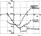
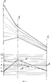
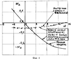
На фиг.1 показана схема интегрального самолета. На фиг.2 - результаты продувок модели при общепринятой схеме закрученности профилей на крыле. На фиг.3 - новый закон изменения закрученности профилей в единой системе. На фиг.4 - экспериментальные данные, полученные при продувках новой модели в аэродинамической трубе.Figure 1 shows a diagram of an integrated aircraft. Figure 2 - the results of purging the model with the generally accepted pattern of swirling profiles on the wing. Figure 3 is a new law of changing the curl of the profiles in a single system. Figure 4 - experimental data obtained by blowing a new model in a wind tunnel.
Самолет 1 (фиг.1) состоит из интегрального узла 2, в который входит передняя часть с кабиной экипажа 3, фюзеляж 4, переходящий в крыло 5, состоящего из наплыва 6 и консоли 7. Самолет имеет вертикальное 8 и горизонтальное 9 оперения центроплана с рулями 10 и 11. Силовая установка состоит из двигателей 12. На самолете установлены самолетные и двигательные системы, оборудование и приборы, которые условно не показаны.The plane 1 (Fig. 1) consists of an
Все режимы и этапы полета на самолете интегральной схемы выполняются без ограничений и не требуют особого мастерства.All flight modes and stages on an integrated circuit aircraft are performed without restrictions and do not require special skill.
Но на больших углах атаки из-за отрыва потока в начале наплыва появляется значительный продольный момент (фиг.2), который по мере увеличения угла атаки увеличивается и становится недопустимым.But at large angles of attack due to flow separation at the beginning of the influx, a significant longitudinal moment appears (Fig. 2), which increases with increasing angle of attack and becomes unacceptable.
Экспериментальные и теоретические исследования показали, что причина такого явления заключается в том, что, применяя общепринятую схему изменения угла закрученности профилей по размаху крыла (фиг.3, линия «А»), которая действительно помогает улучшить характеристики поведения консоли на больших углах атаки (срыв идет от корневого сечения и медленно идет вдоль размаха), получаем недопустимый продольный момент из-за большого размера корневой хорды даже при незначительном срыве потока. В интегральной схеме необходимо изменить положение начала срыва и перенести его в положение, где длина хорды невелика. Более того, желательно в этих сечениях крыла применить сверхкритический профиль с моментными характеристиками, которые уравновесят в этих сечениях кабрирующий продольный момент. Было определено, что наилучшим образом эту задачу можно решить, применяя закон изменения углов закрученности по размаху, который показан на фиг.3 (линия «В»). При этом обеспечивается отрицательная закрученность профилей на бортовой нервюре (до -3°), положительная закрученность на линии перехода наплыв-консоль (до +2°) и отрицательная закрученность на бортовой нервюре (до -3°). Закон изменения углов закрученности между указанными базовыми сечениями принят линейным.Experimental and theoretical studies have shown that the reason for this phenomenon is that, using the generally accepted scheme for changing the torsion angle of the profiles along the wing span (Fig. 3, line “A”), which really helps to improve the behavior of the console at large angles of attack (stall comes from the root section and goes slowly along the span), we get an unacceptable longitudinal moment due to the large size of the root chord, even with a slight stall. In the integrated circuit, it is necessary to change the position of the beginning of the breakdown and move it to a position where the length of the chord is small. Moreover, it is advisable to use a supercritical profile with moment characteristics in these wing sections, which will balance the longitudinal longitudinal moment in these sections. It was determined that in the best way this problem can be solved by applying the law of variation of the swirl angles in scope, which is shown in figure 3 (line "B"). At the same time, negative swirling of the profiles on the side rib (up to -3 °), positive swirling on the influx-cantilever transition line (up to + 2 °) and negative swirling on the side rib (up to -3 °) are ensured. The law of variation of the torsion angles between the indicated base sections is adopted linear.
На фиг.4 показаны новые характеристики интегрального самолета при применении нового закона закрученности профилей. Очевидно, что во всем исследованном диапазоне углов атаки самолет устойчив и имеет высокие аэродинамические характеристики.Figure 4 shows the new characteristics of an integrated aircraft when applying the new law of twist profiles. Obviously, in the entire investigated range of angles of attack, the aircraft is stable and has high aerodynamic characteristics.
Claims (1)
Priority Applications (1)
| Application Number | Priority Date | Filing Date | Title |
|---|---|---|---|
| RU2007103109/11A RU2351503C2 (en) | 2007-01-26 | 2007-01-26 | Integral configuration aircraft |
Applications Claiming Priority (1)
| Application Number | Priority Date | Filing Date | Title |
|---|---|---|---|
| RU2007103109/11A RU2351503C2 (en) | 2007-01-26 | 2007-01-26 | Integral configuration aircraft |
Publications (2)
| Publication Number | Publication Date |
|---|---|
| RU2007103109A RU2007103109A (en) | 2008-08-10 |
| RU2351503C2 true RU2351503C2 (en) | 2009-04-10 |
Family
ID=39745761
Family Applications (1)
| Application Number | Title | Priority Date | Filing Date |
|---|---|---|---|
| RU2007103109/11A RU2351503C2 (en) | 2007-01-26 | 2007-01-26 | Integral configuration aircraft |
Country Status (1)
| Country | Link |
|---|---|
| RU (1) | RU2351503C2 (en) |
Families Citing this family (1)
| Publication number | Priority date | Publication date | Assignee | Title |
|---|---|---|---|---|
| US11891171B1 (en) | 2023-06-12 | 2024-02-06 | Faruk Dizdarevic | Aircraft wing with tiplet |
Citations (2)
| Publication number | Priority date | Publication date | Assignee | Title |
|---|---|---|---|---|
| RU2174089C1 (en) * | 2000-10-13 | 2001-09-27 | Карклин Андрей Михайлович | Aircraft with lifting fuselage |
| WO2002079031A2 (en) * | 2001-01-19 | 2002-10-10 | The Boeing Company | Integrated and/or modular high-speed aircraft |
-
2007
- 2007-01-26 RU RU2007103109/11A patent/RU2351503C2/en not_active IP Right Cessation
Patent Citations (2)
| Publication number | Priority date | Publication date | Assignee | Title |
|---|---|---|---|---|
| RU2174089C1 (en) * | 2000-10-13 | 2001-09-27 | Карклин Андрей Михайлович | Aircraft with lifting fuselage |
| WO2002079031A2 (en) * | 2001-01-19 | 2002-10-10 | The Boeing Company | Integrated and/or modular high-speed aircraft |
Non-Patent Citations (1)
| Title |
|---|
| РИГМАНТ В.Г. САМОЛЕТЫ ОКБ А.Н.ТУПОЛЕВА. - М.: РУСАВИА, 2001, с.244-249. * |
Also Published As
| Publication number | Publication date |
|---|---|
| RU2007103109A (en) | 2008-08-10 |
Similar Documents
| Publication | Publication Date | Title |
|---|---|---|
| US10661884B2 (en) | Oblique blended wing body aircraft | |
| RU2440916C1 (en) | Aircraft in integral aerodynamic configuration | |
| US6578798B1 (en) | Airlifting surface division | |
| EP3880555B1 (en) | Double wing aircraft | |
| CN1571745B (en) | Aircraft construction with improved aerodynamic performance | |
| US10723444B2 (en) | Spin resistant aircraft configuration | |
| US10899447B2 (en) | Methods for improvements of the box wing aircraft concept and corresponding aircraft configuration | |
| US20060016931A1 (en) | High-lift, low-drag dual fuselage aircraft | |
| RU2351503C2 (en) | Integral configuration aircraft | |
| Lowry | Data on spoiler-type ailerons | |
| US20140151511A1 (en) | Aircraft with at least two aircraft fuselages and two main wings | |
| RU2351507C2 (en) | High-lift fuselage aircraft | |
| RU2719522C1 (en) | Aerodynamic surface tip | |
| Merryisha et al. | Wing engineering: aerodynamics, structures and design | |
| RU2728017C2 (en) | Short take-off and landing aircraft | |
| RU2632550C1 (en) | Aircraft | |
| Bishop | The development of tailless aircraft and flying wings | |
| RU2412861C1 (en) | Mukhamedov's wing | |
| RU50977U1 (en) | REVERSE SWEEP WING WITH TURNING PART OF THE CONSOLE | |
| RU2349499C2 (en) | Horizontal tail of integrated structure aircraft | |
| RU2842754C1 (en) | Aircraft aerodynamic configuration | |
| Dimitriadis | Fighter aircraft design | |
| RU2362693C2 (en) | Self-stabilising wing-in-ground effect craft | |
| RU2177895C1 (en) | Aerobatic trainer airplane як-54 | |
| WO2020145837A1 (en) | Lifting surface |
Legal Events
| Date | Code | Title | Description |
|---|---|---|---|
| MM4A | The patent is invalid due to non-payment of fees |
Effective date: 20190127 |