RU2339986C2 - Spectacles - Google Patents
Spectacles Download PDFInfo
- Publication number
- RU2339986C2 RU2339986C2 RU2006139829/28A RU2006139829A RU2339986C2 RU 2339986 C2 RU2339986 C2 RU 2339986C2 RU 2006139829/28 A RU2006139829/28 A RU 2006139829/28A RU 2006139829 A RU2006139829 A RU 2006139829A RU 2339986 C2 RU2339986 C2 RU 2339986C2
- Authority
- RU
- Russia
- Prior art keywords
- rim
- flat
- glasses
- mating element
- bow
- Prior art date
Links
Images


Classifications
-
- G—PHYSICS
- G02—OPTICS
- G02C—SPECTACLES; SUNGLASSES OR GOGGLES INSOFAR AS THEY HAVE THE SAME FEATURES AS SPECTACLES; CONTACT LENSES
- G02C5/00—Constructions of non-optical parts
- G02C5/22—Hinges
-
- G—PHYSICS
- G02—OPTICS
- G02C—SPECTACLES; SUNGLASSES OR GOGGLES INSOFAR AS THEY HAVE THE SAME FEATURES AS SPECTACLES; CONTACT LENSES
- G02C5/00—Constructions of non-optical parts
- G02C5/008—Spectacles frames characterized by their material, material structure and material properties
-
- G—PHYSICS
- G02—OPTICS
- G02C—SPECTACLES; SUNGLASSES OR GOGGLES INSOFAR AS THEY HAVE THE SAME FEATURES AS SPECTACLES; CONTACT LENSES
- G02C1/00—Assemblies of lenses with bridges or browbars
- G02C1/06—Bridge or browbar secured to or integral with closed rigid rims for the lenses
- G02C1/08—Bridge or browbar secured to or integral with closed rigid rims for the lenses the rims being tranversely split and provided with securing means
-
- G—PHYSICS
- G02—OPTICS
- G02C—SPECTACLES; SUNGLASSES OR GOGGLES INSOFAR AS THEY HAVE THE SAME FEATURES AS SPECTACLES; CONTACT LENSES
- G02C5/00—Constructions of non-optical parts
- G02C5/14—Side-members
-
- G—PHYSICS
- G02—OPTICS
- G02C—SPECTACLES; SUNGLASSES OR GOGGLES INSOFAR AS THEY HAVE THE SAME FEATURES AS SPECTACLES; CONTACT LENSES
- G02C5/00—Constructions of non-optical parts
- G02C5/22—Hinges
- G02C5/2209—Pivot bearings and hinge bolts other than screws
-
- G—PHYSICS
- G02—OPTICS
- G02C—SPECTACLES; SUNGLASSES OR GOGGLES INSOFAR AS THEY HAVE THE SAME FEATURES AS SPECTACLES; CONTACT LENSES
- G02C5/00—Constructions of non-optical parts
- G02C5/22—Hinges
- G02C5/2218—Resilient hinges
- G02C5/2254—Resilient hinges comprising elastic means other than coil spring
-
- G—PHYSICS
- G02—OPTICS
- G02C—SPECTACLES; SUNGLASSES OR GOGGLES INSOFAR AS THEY HAVE THE SAME FEATURES AS SPECTACLES; CONTACT LENSES
- G02C2200/00—Generic mechanical aspects applicable to one or more of the groups G02C1/00 - G02C5/00 and G02C9/00 - G02C13/00 and their subgroups
- G02C2200/12—Frame or frame portions made from sheet type material
-
- G—PHYSICS
- G02—OPTICS
- G02C—SPECTACLES; SUNGLASSES OR GOGGLES INSOFAR AS THEY HAVE THE SAME FEATURES AS SPECTACLES; CONTACT LENSES
- G02C2200/00—Generic mechanical aspects applicable to one or more of the groups G02C1/00 - G02C5/00 and G02C9/00 - G02C13/00 and their subgroups
- G02C2200/22—Leaf spring
Abstract
Description
Настоящее изобретение относится к очкам или, соответственно, к оправе очков, а также к ободу очков и дужке очков для такой оправы очков.The present invention relates to glasses or, respectively, to the frame of glasses, as well as to the rim of glasses and the temple of glasses for such a frame of glasses.
Из предшествующего уровня техники известны различные типы соединительных механизмов для оправ очков. Наиболее общий тип основан на шарнирном механизме, в котором штифты, расположенные на оправе или, соответственно, на ободе оптических стекол, взаимодействуют с соответствующим шарниром, который расположен на конце боковой поверхности дужки, которая находится на боковой поверхности обода, разделяя обе детали и соединяя их посредством специальных винтов так, чтобы они поворачивались. В большинстве ободов очков, в частности, в тех, которые используют с корректирующими оптическими стеклами, открывание и закрывание ободов для вставления или для замены оптических стекол осуществляют посредством, так называемого, запирающего блока. Оптические стекла могут быть также непосредственно присоединены к оправе посредством винтов, ввинчивающихся непосредственно в оптические стекла. В очках без оправы дужки непосредственно соединены винтами с оптическими стеклами благодаря выступающей части.Various types of coupling mechanisms for eyeglass frames are known in the art. The most common type is based on the hinge mechanism, in which the pins located on the frame or, respectively, on the rim of the optical glasses interact with the corresponding hinge, which is located on the end of the side surface of the bow, which is located on the side surface of the rim, separating both parts and connecting them by means of special screws so that they turn. In most glasses rims, in particular those used with corrective optical glasses, the opening and closing of the rims for inserting or for replacing optical glasses is carried out by means of a so-called locking unit. Optical glasses can also be directly attached to the frame by means of screws that screw directly onto the optical glasses. In rimless glasses, the arms are directly connected by screws to optical glasses thanks to the protruding part.
Поскольку шарнирное соединение подвергается воздействию больших динамических нагрузок в течение срока жизни очков, в некоторых решениях по причинам упрощения не используют традиционного шарнирного соединения.Since the swivel is subjected to high dynamic loads during the life of the glasses, in some solutions, for reasons of simplification, do not use a traditional swivel.
Так, в патентной заявке США №3155982 предлагаются очки, в которых дужки непосредственно взаимодействуют с передней частью обода, который удерживает оптические стекла. По этой причине конец дужки, который находится на боковой поверхности обода, разделен на три плоские (пластинчатые) пружины, причем центральная плоская пружина опирается на внешний край части обода, тогда как две внешние плоские пружины сцепляются с отверстиями, расположенными вблизи внешнего края центральной части, посредством крюков, образованных на их концах. Недостатком соединительного механизма, описанного в патентной заявке США №3155982, является тот факт, что дужки очков присоединены к ободу только очень свободно, так что дужки очков могут очень просто освобождаться от держателя, например, когда очки падают на пол.So, in US patent application No. 3155982, glasses are offered in which the arms directly interact with the front of the rim that holds the optical glasses. For this reason, the end of the handle, which is located on the side surface of the rim, is divided into three flat (leaf) springs, the central flat spring resting on the outer edge of the rim, while the two outer flat springs are engaged with holes located near the outer edge of the central part, by means of hooks formed at their ends. A disadvantage of the connecting mechanism described in US patent application No. 3155982 is the fact that the earcups of the glasses are attached to the rim only very loosely, so that the earcups of the glasses can very easily be released from the holder, for example, when the glasses fall to the floor.
Другое решение для соединения очков, в котором также использованы дужки очков, которые предусмотрены с тремя плоскими пружинами, предложено в европейском патенте №0863424 В1, выданном Хаффмансу и Готтшлингу. На ободе, соответственно, по одному соединительному элементу предусмотрено на левой и правой стороне, который имеет верхнее и нижнее углубление, которое образует ось соединения, которая перпендикулярна направлению дужки в ее сложенном состоянии. В сложенном состоянии дужек две плоские пружины дужек сцепляются с углублениями в соединительном элементе из поверхности соединительного элемента, которая обращена к лицу того, на кого надеты очки, посредством криволинейных конфигураций, которые предусмотрены на их свободных концах, и затем опираются на поверхность соединительного элемента, которая не обращена к лицу того, на кого надеты очки, тогда как центральная плоская пружина опирается по всей ее длине на противоположную поверхность соединительного элемента. Соединительный элемент разделен на две части, таким образом, предоставляется простая возможность для замены оптических стекол. Для стабилизации может быть использован запирающий зажим, который может опрокидывать соединительный элемент, состоящий из двух частей. Однако этот механизм имеет тот недостаток, что вставление дужек затруднено, поскольку внешние плоские пружины и центральную плоскую пружину приходится направлять на противоположных поверхностях соединительного элемента, причем эта операция должна выполняться путем движения против действия упругой деформации, и нарушаются криволинейные конфигурации концов. Кроме того, особенно в том случае, если размеры этого соединения очень малы, существует опасность того, что дужки отсоединятся от соединительного элемента даже в случае небольшой механической нагрузки.Another solution for connecting glasses, which also uses the temples of the glasses, which are provided with three flat springs, is proposed in European patent No. 0863424 B1, issued to Huffmans and Gottschling. On the rim, respectively, one connecting element is provided on the left and right side, which has an upper and lower recess, which forms the axis of the connection, which is perpendicular to the direction of the bow in its folded state. When the arches are folded, two flat arches springs are engaged with recesses in the connecting element from the surface of the connecting element, which faces the face of the person wearing the glasses, by means of the curved configurations provided at their free ends, and then rest on the surface of the connecting element, which not facing the face of the person on whom the glasses are worn, while the central flat spring rests along its entire length on the opposite surface of the connecting element. The connecting element is divided into two parts, thus providing a simple opportunity for replacing optical glasses. For stabilization, a locking clip can be used, which can overturn a two-piece connecting element. However, this mechanism has the disadvantage that the insertion of the arches is difficult, since the outer flat springs and the central flat spring have to be directed on opposite surfaces of the connecting element, this operation must be performed by moving against the action of elastic deformation, and the curvilinear configurations of the ends are violated. In addition, especially if the dimensions of this connection are very small, there is a danger that the arms will come off from the connecting element even in the case of a small mechanical load.
Из французской публикации FR 2779241 известна оправа очков, имеющая соединение очков, которое получают путем наличия штифтов на конце дужки на боковой поверхности обода, которые сцепляются с углублениями соединительного элемента на ободе, причем зажимы соединительного элемента перекрывают конец на боковой поверхности обода при складывании дужек. Однако такое соединение не гарантирует надежного удерживания дужки в случае чрезмерной механической нагрузки.From the French publication FR 2779241, a spectacle frame is known having a spectacle connection, which is obtained by having pins at the end of the handle on the side surface of the rim that engage with recesses of the connecting element on the rim, the clamps of the connecting element overlapping the end on the side surface of the rim when folding the arms. However, such a connection does not guarantee reliable retention of the bow in case of excessive mechanical stress.
В патентной заявке WO 98/148313 описан соединительный механизм, в котором два пальца, по одному, смонтированному на каждом из концов стороны соединения дужки очков, отогнуты друг от друга, и изогнутые концы сцепляются с возможностью поворота в апертурах, которые расположены на соединительном элементе на боковой поверхности оправы. Изогнутые концы пальцев надежно удерживаются в этих апертурах благодаря тому, что эти пальцы прикладывают некоторую пружинную упругость вверх и вниз. Однако такой соединительный механизм не ассоциируется с плоскими металлическими очками, подобными тем, которые, например, описаны в патенте ЕР 0863424 В1.Patent application WO 98/148313 describes a connecting mechanism in which two fingers, one mounted on each end of the connecting side of the eyeglass earpiece, are bent from each other, and the curved ends engage rotatably in apertures that are located on the connecting element on side surface of the frame. The curved ends of the fingers are held securely in these apertures due to the fact that these fingers apply some spring elasticity up and down. However, such a connecting mechanism is not associated with flat metal glasses, similar to those described, for example, in patent EP 0863424 B1.
Исходя из этого, задачей настоящего изобретения является получение оправы очков, которая обеспечивает возможность простого монтажа дужек и в которой становится затруднительным для дужек очков ослабляться независимо от механического нажима на очки, в частности, в плоских металлических очках.Based on this, the object of the present invention is to provide a spectacle frame that enables easy mounting of the arches and in which it becomes difficult for the arches of the glasses to loosen regardless of mechanical pressure on the glasses, in particular in flat metal glasses.
Эту задачу решают с помощью оправы очков, описанной в пунктах 1, 7 и 11 формулы изобретения, обода очков по пункту 5, дужки по пункту 3 и 9, очков по пункту 15, а также с помощью способа получения дужек очков по пункту 18 формулы изобретения.This problem is solved using the eyeglass frames described in
Предпочтительные варианты осуществления настоящего изобретения могут быть очевидными из зависимых пунктов формулы изобретения.Preferred embodiments of the present invention may be apparent from the dependent claims.
Следовательно, главным вопросом настоящего изобретения является то, что дужки оправы очков на их концах по направлению к боковой поверхности обода имеют, по меньшей мере, два пальца в их продольном направлении, которые сконфигурированы так, чтобы они прикладывали пружинное воздействие по существу в направлении оси соединения шарнира, образованного соединительными элементами сопрягающего элемента на ободе и взаимодействием соединительных элементов дужки очков, и эти пальцы удерживают соединительные элементы дужек и сопрягающего элемента в поворотном и надежном соединении, и что эти пальцы в то же самое время конфигурированы как плоские пружины, плоская поверхность которых, когда дужка развернута, проходит по существу в плоскости сопрягающего элемента, принадлежащего дужке, сопрягающий элемент которой также имеет почти плоскую форму.Therefore, the main issue of the present invention is that the frames of the eyeglass frames at their ends towards the side surface of the rim have at least two fingers in their longitudinal direction, which are configured so that they apply a spring action essentially in the direction of the connection axis the hinge formed by the connecting elements of the mating element on the rim and the interaction of the connecting elements of the bow of the glasses, and these fingers hold the connecting elements of the arms and the mating element coagulant in the rotary and reliable connection, and that the fingers at the same time configured as leaf springs, flat surface which, when the yoke is deployed, extends substantially in the plane of the mating element belonging to the arc, wherein the mating member also has an almost flat shape.
В одном варианте осуществления оправы очков пальцы сконфигурированы так, чтобы сила пружины, прикладываемая, по меньшей мере, одним пальцем, была эффективной в направлении к другому пальцу.In one embodiment of the eyeglass frame, the fingers are configured so that the spring force exerted by at least one finger is effective in the direction of the other finger.
Такую конструкцию используют особенно в предпочтительном варианте осуществления оправы очков, в котором сопрягающий элемент разделен по его длине на верхнюю полосу и нижнюю полосу. Разделение сопрягающего элемента проходит через обод к оптическим стеклам очков. Это делает замену оптических стекол очков простой операцией, поскольку с удаленными дужками боковые поверхности обода могут быть просто отогнутыми, делая доступными оптические стекла.This design is used especially in a preferred embodiment of the spectacle frame, in which the mating element is divided along its length into an upper strip and a lower strip. The separation of the mating element passes through the rim to the optical glasses of the glasses. This makes replacing the optical glasses of the glasses a simple operation, since with the removed temples the side surfaces of the rim can simply be bent, making the optical glasses available.
При смонтированных дужках жесткость пружины пальцев, в конечном счете, делает возможным напряжение полос друг против друга и оптические стекла надежно зафиксированы в соответствующей секции обода.When the arches are mounted, the stiffness of the fingers spring ultimately makes it possible to tension the strips against each other and the optical glasses are securely fixed in the corresponding section of the rim.
В этой конструкции дужки имеют соединительные элементы на пальцах в форме петель, тогда как соответствующие шарнирные пальцы предусмотрены на соответствующих элементах. Петли проходят по существу перпендикулярно к плоскости или поверхности дужки. При смонтированной дужке, следовательно, шарнирные пальцы сопрягающего элемента захватываются в петлях пальцев, так что пружинный эффект пальцев удерживает петли постоянно поддающимися повороту на шарнирных пальцах.In this design, the arms have connecting elements on the fingers in the form of loops, while corresponding articulated fingers are provided on the corresponding elements. The loops extend substantially perpendicular to the plane or surface of the bow. With the bow mounted, therefore, the articulated fingers of the mating element are caught in the loops of the fingers, so that the spring effect of the fingers keeps the loops constantly rotatable on the articulated fingers.
В другом варианте осуществления шарнирные пальцы сопрягающего элемента сконфигурированы так, чтобы они с возможностью поворота вставлялись в соответствующие вогнутые втулки подшипников пальцев, причем втулки расположены друг против друга, а также в этом случае крепились упругостью пружины пальцев, так что втулки подшипников постоянно удерживаются в поворотном контакте посредством шарнирного пальца сопрягающего элемента.In another embodiment, the articulated fingers of the mating element are configured to be pivotally inserted into respective concave bushings of the finger bearings, the bushings being opposed to each other, and in this case also being attached by the spring tension of the fingers, so that the bearing bushings are constantly held in rotary contact by the articulated finger of the mating element.
Простым образом пальцы могут быть растянуты против их пружинного действия для освобождения дужек из сопрягающего элемента и чтобы сделать обод доступным для замены оптических стекол очков.In a simple manner, the fingers can be stretched against their spring action to release the arches from the mating element and to make the rim available for replacing the optical glasses of the glasses.
В другом варианте осуществления оправы очков пальцы сконструированы так, чтобы сила пружины, прикладываемая, по меньшей мере, одним пальцем, действовала в обратном направлении, то есть, в направлении от другого пальца.In another embodiment of the eyeglass frame, the fingers are designed so that the force of the spring applied by at least one finger acts in the opposite direction, that is, in the direction from the other finger.
Затем соответствующим способом петли предусмотрены на сопрягающем элементе, в котором сцепляются шарнирные пальцы, которые выступают вверх и вниз из пальцев. Отверстия петель проходят по существу перпендикулярно плоскости или поверхности сопрягающих элементов. Упругость пружины препятствует любому освобождению шарнирного пальца из петель, образуя в то же самое время простое шарнирное соединение. Для демонтажа дужек достаточно просто сдавить пальцы дужки вместе против направления действия силы пружины.Then, in an appropriate manner, loops are provided on the mating element in which articulated fingers engage that protrude up and down from the fingers. The holes of the loops extend substantially perpendicular to the plane or surface of the mating elements. The elasticity of the spring prevents any release of the hinge pin from the loops, forming at the same time a simple hinge joint. To dismantle the arms, simply squeeze the fingers together against the direction of action of the spring force.
Помимо пальцев, сконфигурированных как плоские пружины, в другом варианте осуществления между этими двумя элементами предусмотрена третья центральная плоская пружина, причем все плоские пружины проходят параллельно друг другу.In addition to the fingers configured as flat springs, in another embodiment, a third central flat spring is provided between the two elements, all flat springs being parallel to each other.
Дужка может быть просто получена штамповкой из плоского жесткого материала вместе с плоскими пружинами и петлями в течение одной технологической операции. Следовательно, петли могут быть изогнуты так, чтобы они проходили по существу перпендикулярно плоскости дужки.The bow can simply be obtained by stamping from a flat rigid material together with flat springs and loops during one technological operation. Therefore, the loops can be bent so that they extend substantially perpendicular to the plane of the bow.
Хотя внешние из трех плоских пружин образуют соединительные элементы - в зависимости от варианта осуществления петли или шарнирные пальцы - центральная плоская пружина служит для образования обратного пружинного механизма, который поддерживает разложенную или сложенную дужку.Although the outer of the three flat springs form the connecting elements — depending on the embodiment, loops or pivot pins — the central flat spring serves to form an inverse spring mechanism that supports the unfolded or folded arm.
Для этой цели центральная плоская пружина поддерживает себя на секции сопрягающего элемента, которая проходит по направлению к дужке и, таким образом, образует упор.For this purpose, the central flat spring supports itself on the section of the mating element, which extends towards the bow and, thus, forms a stop.
В соответствии с настоящим изобретением, таким образом, гарантируется то, что длина плоской пружины и длина упора выбраны такими, что упругость пружины, с одной стороны, достаточна для достижения надежного соединения соединительных элементов дужки и сопрягающего элемента, а с другой стороны, упругость плоской пружины центральной плоской пружины дужки достаточна для удерживания дужки в разложенном положении. Помимо всего прочего, в варианте осуществления с двумя полосами сопрягающего элемента, длины соответствующих элементов выбраны такими, чтобы, помимо всего прочего, упругость пружины была достаточной для достижения надежного соединения обеих полос сопрягающего элемента.In accordance with the present invention, it is thus guaranteed that the length of the flat spring and the length of the stop are chosen such that the spring elasticity, on the one hand, is sufficient to achieve a reliable connection of the connecting elements of the bow and the mating element, and on the other hand, the elasticity of the flat spring the central flat spring of the bow is sufficient to hold the bow in the unfolded position. Among other things, in the embodiment with two strips of the mating element, the lengths of the respective elements are selected such that, among other things, the spring elasticity is sufficient to achieve a reliable connection of both strips of the mating element.
Если плоский упор в одном варианте осуществления оправы очков проходит от соединительных элементов сопрягающего элемента по направлению к дужке, то он, таким образом, конфигурируется так, чтобы внешние плоские пружины могли проходить наружу поверх упора во время складывания.If the flat stop in one embodiment of the eyeglass frame extends from the connecting elements of the mating element towards the bow, then it is thus configured so that the outer flat springs can extend outward over the stop during folding.
Для достижения дополнительной стабильности в соответствии с настоящим изобретением также возможно предусматривать втулку, которая может быть с возможностью скольжения перемещена прежде, чем дужка движется вперед посредством сопрягающего элемента, принадлежащего дужке, и, таким образом, жестко скрепляет полосы вместе против изгиба.In order to achieve additional stability in accordance with the present invention, it is also possible to provide a sleeve that can be slidably moved before the handle moves forward by means of a mating member belonging to the handle, and thus rigidly fastens the strips together against bending.
Все элементы оправы очков, соответствующей настоящему изобретению, могут быть получены в предпочтительном варианте осуществления как штампованные детали или составные детали, полученные из металлического листа, которые затем изогнуты в требуемой заключительной конфигурации. В качестве материала для отдельных элементов можно также использовать титан.All the eyeglass frame elements of the present invention can be obtained in a preferred embodiment as stamped parts or composite parts obtained from a metal sheet, which are then bent in the desired final configuration. Titanium can also be used as material for individual elements.
Далее настоящее изобретение будет более подробно описано со ссылками на варианты осуществления, показанные на прилагаемых иллюстрациях.The present invention will now be described in more detail with reference to the embodiments shown in the accompanying illustrations.
КРАТКОЕ ОПИСАНИЕ ЧЕРТЕЖЕЙBRIEF DESCRIPTION OF THE DRAWINGS
Фиг.1 - изометрическое изображение дужки для оправы очков, соответствующей предшествующему уровню техники.Figure 1 - isometric image of the temple for the frames of glasses, corresponding to the prior art.
Фиг.2а - изометрическое изображение нефасонной дужки для оправы очков, соответствующей настоящему изобретению, с петлями, спрофилированными для пригонки.Fig. 2a is an isometric view of a non-molded earhook for the eyeglass frames of the present invention, with loops profiled for fit.
Фиг.2b - изометрическое изображение фасонной дужки для оправы очков, соответствующей настоящему изобретению, с наклонными петлями, спрофилированными для пригонки.Fig. 2b is an isometric view of a shaped bar for a spectacle frame according to the present invention, with inclined loops profiled for fit.
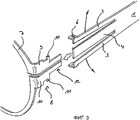
Фиг.3 - изометрическое изображение с пространственным разделением деталей половины оправы очков, соответствующей настоящему изобретению.Figure 3 is an isometric image with a spatial separation of the parts of the half frames of the glasses, corresponding to the present invention.
Фиг.4а - схематическое изображение дужки и обода оправы очков, соответствующей настоящему изобретению, с дужкой в разложенном положении.Fig. 4a is a schematic illustration of a handle and a rim of a spectacle frame according to the present invention with the handle in the unfolded position.
Фиг.4b - схематическое изображение дужки и обода оправы очков, соответствующей настоящему изобретению, с дужкой в сложенном положении.Fig. 4b is a schematic illustration of the temple and the rim of the eyeglass frame of the present invention with the temple in the folded position.
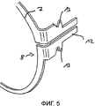
Фиг.5 - иллюстрация сопрягающего элемента с альтернативными соединительными элементами.5 is an illustration of a mating element with alternative connecting elements.
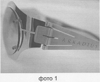
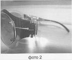
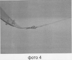
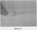
На фото 1-10 - иллюстрации очков по настоящему изобретению.On a photo 1-10 - illustrations of glasses of the present invention.
ПОДРОБНОЕ ОПИСАНИЕ ЧЕРТЕЖЕЙDETAILED DESCRIPTION OF THE DRAWINGS
На фиг.1 в качестве примера показана дужка 1, соответствующая известному уровню техники, например дужка, описанная в патенте ЕР 0863424 В1. Дужка 1 разделена на три плоские пружины 2, 3 и 4, на две внешние плоские пружины 2 и 3 и центральную плоскую пружину 4. Внешние плоские пружины 2 и 3 имеют на своих концах изгибы 5, которые сцепляются в соответствующих углублениях (не иллюстрируемых дополнительно в этой заявке) сопрягающего элемента обода. Как указано ранее, в этом случае центральная плоская пружина 4 и внешние плоские пружины 2 и 3 лежат на противоположных сторонах сопрягающего элемента оправы очков, что препятствует простому отделению дужки.Figure 1 shows, by way of example, a
На фиг.2а и фиг.2b приведены схематические изображения дужки 1 для оправы очков, соответствующей настоящему изобретению.On figa and fig.2b shows a schematic representation of the
Дужка 1 очков также имеет две внешние плоские пружины 2 и 3, а также центральную плоскую пружину 4. Каждая из внешних плоских пружин 2 и 3 имеет на своих концах петлю 6.The
Фиг.2а показывает в этом соединении форму дужки 1 очков в виде штампованной стальной металлической детали, тогда как на фиг.2b петли 6 отогнуты перпендикулярно продольному направлению дужки 1 очков для ограничения оси шарнирного соединения.Fig. 2a shows in this connection the shape of the bow of the
Дужка очков, иллюстрируемая на фиг.2b, по сравнению с дужкой очков, иллюстрируемой на фиг.1, имеет более длинные прорези для деления плоских пружин, чтобы упростить разделение двух внешних плоских пружин перпендикулярно продольному направлению дужки, как более подробно описано ниже.The eyeglass bar illustrated in FIG. 2b, compared with the eyeglass bar illustrated in FIG. 1, has longer slots for dividing the flat springs in order to simplify the separation of the two outer flat springs perpendicular to the longitudinal direction of the arm, as described in more detail below.
На фиг.3 показана дужка очков, отделенная от обода 7.Figure 3 shows the temple of the glasses, separated from the rim 7.
Обод 7 на обеих сторонах имеет сопрягающий элемент 8, который по сравнению с длиной дужки является относительно коротким, проходит по направлению к дужке 1 и делится на верхнюю полосу 9 и нижнюю полосу 10.The rim 7 on both sides has a
Как следует из фиг.3, деление сопрягающего элемента проходит в передней части обода 7 вследствие оптических стекол очков, которые здесь не иллюстрируются. При удалении дужки 1 очков обод может просто открываться в боковом направлении, так как полосы 9 и 10 отгибаются друг от друга для вставления или замены оптических стекол очков.As follows from figure 3, the division of the mating element takes place in front of the rim 7 due to the optical glasses, which are not illustrated here. When removing the earpiece of 1 point, the rim can simply open laterally, since the
На полосах 9 и 10 сопрягающего элемента 8 располагаются шарнирные пальцы 11, перекрывающие друг друга при образовании оси поворота, причем пальцы сцепляются в петлях 6 внешних плоских пружин 2 и 3 дужки 1 в смонтированном положении, как показано на фиг.4а и фиг.4b, и, таким образом, образуют простое шарнирное соединение.On the
Как можно видеть из фиг.3, дужка 1 просто прикреплена на сопрягающем элементе 8 благодаря наличию внешних плоских пружин 2 и 3, разделенных и скользящих поверх шарнирного пальца 11. Пружинное действие внешних плоских пружин 2 и 3 по направлению друг к другу побуждает петли 6 защелкиваться надежно, но с возможностью поворота вокруг шарнирного пальца 11, помимо всего прочего, побуждая верхнюю полосу 9 и нижнюю полосу 10 жестко крепиться вместе против изгиба.As can be seen from figure 3, the
Сопрягающий элемент 8 имеет плоский упор, который проходит из шарнирного пальца 11 по направлению к дужке 1.The
Как можно видеть из фиг.4а, центральная плоская пружина 4 в развернутом положении приходит в контактное взаимодействие с поверхностью упора 12, поворачиваемого от того, кто носит очки. При развертывании, как показано на фиг.4b, центральная плоская пружина 4 поддерживается на упоре 12 для образования реверсивного пружинного механизма. Упор 12 спрофилирован в этом случае так, чтобы внешние плоские пружины 2 и 3 могли проходить беспрепятственно поверх упора 12 при складывании дужки 1.As can be seen from figa, the Central
На фиг.5 схематически иллюстрируется альтернативный вариант осуществления сопрягающего элемента 8. На этом чертеже показаны сферические шарнирные пальцы 13, которые могут быть размещены с возможностью поворота во втулках подшипников внешних плоских пружин.Figure 5 schematically illustrates an alternative embodiment of the
Claims (19)
Applications Claiming Priority (2)
| Application Number | Priority Date | Filing Date | Title |
|---|---|---|---|
| DE102004023839.1 | 2004-05-13 | ||
| DE102004023839A DE102004023839A1 (en) | 2004-05-13 | 2004-05-13 | glasses |
Publications (3)
| Publication Number | Publication Date |
|---|---|
| RU2006139829A RU2006139829A (en) | 2008-06-20 |
| RU2339986C2 true RU2339986C2 (en) | 2008-11-27 |
| RU2339986C9 RU2339986C9 (en) | 2009-04-27 |
Family
ID=34971285
Family Applications (1)
| Application Number | Title | Priority Date | Filing Date |
|---|---|---|---|
| RU2006139829/28A RU2339986C9 (en) | 2004-05-13 | 2005-05-13 | Spectacles |
Country Status (12)
| Country | Link |
|---|---|
| US (2) | US7344242B2 (en) |
| EP (2) | EP1745325B1 (en) |
| JP (1) | JP4727657B2 (en) |
| KR (1) | KR100892543B1 (en) |
| CN (1) | CN1997932B (en) |
| AT (1) | ATE471530T1 (en) |
| CA (1) | CA2566611C (en) |
| DE (6) | DE202004020521U1 (en) |
| HK (1) | HK1105685A1 (en) |
| PL (1) | PL1745325T3 (en) |
| RU (1) | RU2339986C9 (en) |
| WO (1) | WO2005111700A1 (en) |
Cited By (1)
| Publication number | Priority date | Publication date | Assignee | Title |
|---|---|---|---|---|
| WO2013138145A1 (en) * | 2012-03-14 | 2013-09-19 | Bystritsky Felix | Screw-less rim lock and hinge eyewear and assembly method therefor |
Families Citing this family (55)
| Publication number | Priority date | Publication date | Assignee | Title |
|---|---|---|---|---|
| DE102004027013B4 (en) * | 2004-05-28 | 2006-11-16 | Mykita Gmbh | Spectacle frame with a joint for angling the temples |
| FR2892162A1 (en) * | 2005-10-13 | 2007-04-20 | Nouvelle Idc Internat Design C | Hinged articulation system for spectacle frame, has articulated element comprising prongs to receive lateral pins of another element that includes longitudinal slots defining flexible blade supported on side of former element |
| CN2929742Y (en) * | 2006-05-30 | 2007-08-01 | 深圳市华扬眼镜制造厂 | No screw no welding glasses |
| DE102006044711B4 (en) * | 2006-09-20 | 2013-05-02 | Mykita Studio Gmbh | glasses joint |
| US7905591B2 (en) * | 2006-10-25 | 2011-03-15 | Larry Strobel | Multi-function, folding reading glasses |
| DE202007005735U1 (en) * | 2007-04-20 | 2007-08-02 | Ic! Berlin Brillen Gmbh | Spectacle frame comprises a connecting element having individual parts structured so that they are held permanently in a recess of a holding element by tensioning the connecting element |
| US7588331B2 (en) * | 2007-07-03 | 2009-09-15 | Burnstein Tracey E | Personalizeable wearable and displayable items |
| DE102007048011A1 (en) * | 2007-09-27 | 2009-04-09 | OBE OHNMACHT & BAUMGäRTNER GMBH & CO. KG | Hinge for glasses |
| DE102008020795B4 (en) * | 2008-04-22 | 2016-02-04 | Lutz Paul | Three-part spectacle frame |
| KR100931791B1 (en) | 2009-06-08 | 2009-12-14 | 권두열 | Hinge structure used in glasses |
| JP5336286B2 (en) * | 2009-07-22 | 2013-11-06 | 有限会社 ボンバーデザインワークス | Glass frame frame joint structure |
| CN101639574B (en) * | 2009-08-31 | 2013-09-18 | 深圳市龙岗区横岗镇高雅眼镜厂 | Eyeglass elastic sheet hinge |
| KR101114547B1 (en) * | 2009-10-19 | 2012-02-27 | 유근우 | Eyeglass |
| IT1397620B1 (en) * | 2009-10-23 | 2013-01-18 | Prada Sa | AUCTION FOR GLASSES AND GLASSES INCLUDING THIS AUCTION |
| NZ585644A (en) | 2010-05-26 | 2012-12-21 | Francis William Austin | Modular Eye Glasses with the frame part forming a pivot shaft and the temple arms adapted to attach to the pivot shaft |
| US8894200B2 (en) | 2010-06-30 | 2014-11-25 | Addo Industries, Llc | Innovative and aesthetic alternative to traditional spectacle correction |
| SG184551A1 (en) * | 2010-09-06 | 2012-11-29 | Ic Berlin Brillenproduktions Gmbh | Eyeglass frame and temple |
| DE202010015963U1 (en) | 2010-11-27 | 2011-02-10 | Bitzer, Andreas, Dr. | Combination of joint and locking device for eyeglass frames |
| NZ589698A (en) | 2010-12-03 | 2013-07-26 | Francis William Austin | Eyeglass Hinge Assembly which allows removal of the arms |
| IT1404201B1 (en) * | 2010-12-28 | 2013-11-15 | Immagine Eyewear S R L | ELASTIC HINGE FOR GLASSES |
| FR2972273B1 (en) * | 2011-03-01 | 2013-03-29 | Magic Design Project | JOINING DEVICE OF A WINDOW BRANCH |
| ITTO20110959A1 (en) * | 2011-10-22 | 2012-01-21 | Studio Adriano Architetti Associati | GLASSES AND PROCEDURES FOR THEIR MANUFACTURE |
| FR2982041B1 (en) * | 2011-10-27 | 2014-10-17 | Jrl | MOUNT OF ARTICULATED, REMOVABLE BRANCHES |
| US8827444B1 (en) * | 2012-11-02 | 2014-09-09 | Wing-Cheong Koo | Screw-free connection structure for a frame and temples of eyeglasses |
| DE102014000164A1 (en) | 2013-01-18 | 2014-07-24 | Katrin Voigt | Eyeglass e.g. pod reader eyeglass has definite gap that is provided on outside face of lens before outside face comes to standstill state, so that outside face of lens is protected from mechanical damage |
| CN104142580B (en) * | 2013-06-03 | 2016-10-05 | 理研有限公司 | Multifunctional glasses rack |
| TWM470276U (en) * | 2013-09-06 | 2014-01-11 | si-yi Zhang | Connection device of frame and temple free of screw |
| EP3094610B1 (en) * | 2014-01-13 | 2020-04-15 | Roland Iten Mechanical Luxury SA | One-hand operated glasses |
| WO2016066583A1 (en) * | 2014-10-30 | 2016-05-06 | SAFILO SOCIETÀ AZIONARIA FABBRICA ITALIANA LAVORAZIONE OCCHIALI S.p.A. | A hinge device for connecting the sides to the fronts of spectacle frames, and spectacles including this device |
| WO2016068400A1 (en) * | 2014-10-31 | 2016-05-06 | 김용구 | Coupling structure of glass frame rims which facilitates coupling |
| FR3030287B1 (en) * | 2014-12-22 | 2019-05-10 | Decathlon | GLASSES PARTICULARLY FOR THE PRACTICE OF AQUATIC ACTIVITY |
| US10261338B2 (en) | 2015-01-15 | 2019-04-16 | Addo Industries, Llc | Eyewear comprising suspension system for nose and ears |
| USD774121S1 (en) * | 2015-04-15 | 2016-12-13 | Tifosi Optics Inc. | Sunglasses kit |
| DE102016000299A1 (en) | 2016-01-15 | 2017-07-20 | Katrin Voigt | glasses |
| DE202016000225U1 (en) | 2016-01-15 | 2016-04-20 | Katrin Voigt | glasses |
| KR101656803B1 (en) | 2016-01-21 | 2016-09-12 | 정진백 | Hinge assembly for glasses frame |
| US9989781B2 (en) * | 2016-04-08 | 2018-06-05 | Pamela Arder | Eyeglasses with detachable temples and nose grip and method of use |
| DE102016007228A1 (en) * | 2016-06-15 | 2017-12-21 | Ic!-Berlin Brillen Gmbh | Glasses and glasses |
| US10203517B2 (en) | 2016-07-14 | 2019-02-12 | Roav Inc. | Folding eyeglass frames having a bridge assembly |
| US11029533B2 (en) | 2016-08-30 | 2021-06-08 | Bernard B. Fresco | Glasses with hinge structure with temple clip |
| FR3063152B1 (en) * | 2017-02-23 | 2023-03-03 | Vuillet Vega | GLASSES FRAME ARTICULATION. |
| TW201923415A (en) * | 2017-08-23 | 2019-06-16 | 新加坡商偉創力有限公司 | Light projection engine attachment and alignment |
| KR102047239B1 (en) | 2018-04-13 | 2019-11-21 | 주식회사 이노 (Inno) | A Resilient Hinge assembly for Glasses frame |
| KR102125533B1 (en) | 2018-11-29 | 2020-06-22 | 장용찬 | Elastic hinge assembly for glasses frame |
| US10642050B1 (en) * | 2018-12-14 | 2020-05-05 | Google Llc | Modular accessory systems for wearable devices |
| DE102019200049A1 (en) | 2019-01-04 | 2020-07-09 | Aktiebolaget Skf | A SUSPENSION ASSEMBLY |
| DE102019200048A1 (en) * | 2019-01-04 | 2020-07-09 | Aktiebolaget Skf | Suspension spring |
| USD923694S1 (en) * | 2019-02-25 | 2021-06-29 | Good Citizens Pty Ltd. | Glasses |
| CA3072496A1 (en) | 2019-02-28 | 2020-08-28 | Smith Sport Optics, Inc. | Eyewear lens interchange with magnetic latch |
| USD918292S1 (en) * | 2019-04-30 | 2021-05-04 | WearMePro LLC | Eyeglasses hinge |
| US20220099998A1 (en) * | 2020-09-25 | 2022-03-31 | Shih-Yun Huang | Eyewear hinge device |
| AT524399B1 (en) * | 2020-10-20 | 2022-07-15 | Lasnik Gerald | frame of glasses |
| KR102519375B1 (en) | 2020-11-04 | 2023-04-10 | 주식회사 이노 (Inno) | Hinge assembly for glasses frame |
| USD984523S1 (en) * | 2021-06-15 | 2023-04-25 | Christian Dior Couture | Sunglasses |
| KR20240023870A (en) | 2022-08-16 | 2024-02-23 | 이창우 | Hinge assembly for glasses frames |
Family Cites Families (19)
| Publication number | Priority date | Publication date | Assignee | Title |
|---|---|---|---|---|
| FR954467A (en) * | 1950-01-03 | |||
| DE1686969U (en) * | 1954-06-03 | 1954-11-11 | Heinz Hasel | GLASSES, IN PARTICULAR SUNGLASSES. |
| US3155982A (en) | 1962-05-07 | 1964-11-10 | Pennsylvania Optical Company | Eyeshield |
| US3744887A (en) * | 1972-06-22 | 1973-07-10 | Esb Inc | Plastic hinge for spectacles |
| FR2439412A2 (en) * | 1978-10-20 | 1980-05-16 | Must Cartier France | EYEGLASS FRAME |
| JPS6094626A (en) * | 1983-10-21 | 1985-05-27 | Ishikawa Seisakusho:Kk | Control of sliver unevenness in drawing frame and its device |
| JPH0542419Y2 (en) * | 1988-04-27 | 1993-10-26 | ||
| DE8902196U1 (en) * | 1989-02-24 | 1989-03-30 | Marwitz & Hauser Gmbh, 7000 Stuttgart, De | |
| AT397441B (en) * | 1991-01-17 | 1994-04-25 | Silhouette Int Gmbh | HINGE JOINT BETWEEN BRACKETS AND BRACKET JAWS OF A GLASSES FRAME |
| US5418581A (en) * | 1993-06-07 | 1995-05-23 | Bausch & Lomb Incorporated | Hinge system for eyewear |
| US5532766A (en) * | 1995-09-27 | 1996-07-02 | Al W. Paulsen | Foldable eyeglasses having locking means |
| DE19703812A1 (en) * | 1997-01-27 | 1998-07-30 | Philipp Haffmans | Screwless glasses frame |
| US5847801A (en) * | 1997-04-04 | 1998-12-08 | Masunaga Optical Mfg. Co., Ltd. | Hinge structure and bearing member for hinge in frame of spectacles |
| AU7132298A (en) | 1997-04-18 | 1998-11-13 | Kenneth W. IAMS | Device for viewing stereoscopic images |
| IT1293466B1 (en) * | 1997-04-21 | 1999-03-01 | Galileo Ind Ottiche Spa | METAL FRAME PERFECTED FOR GLASSES |
| FR2779241B1 (en) * | 1998-06-02 | 2000-07-21 | Cebe International Sa | PAIR OF EYEWEAR EQUIPPED WITH ELASTIC HINGES |
| EP1175637A1 (en) * | 1999-05-04 | 2002-01-30 | Angelo Schievenin | Eyeglasses frame and method of preparing and assembling same |
| JP3345407B2 (en) * | 2000-10-11 | 2002-11-18 | 孝二 永吉 | Glasses temple connection structure |
| US6890073B2 (en) * | 2003-03-20 | 2005-05-10 | Liberty Sport, Inc. | Impact resistant eyewear frame assembly having a split frame |
-
2004
- 2004-05-13 DE DE202004020521U patent/DE202004020521U1/en not_active Expired - Lifetime
- 2004-05-13 DE DE102004023839A patent/DE102004023839A1/en not_active Withdrawn
-
2005
- 2005-05-10 US US11/125,793 patent/US7344242B2/en active Active
- 2005-05-13 CN CN2005800235928A patent/CN1997932B/en active Active
- 2005-05-13 RU RU2006139829/28A patent/RU2339986C9/en not_active IP Right Cessation
- 2005-05-13 JP JP2007511859A patent/JP4727657B2/en active Active
- 2005-05-13 PL PL05753628T patent/PL1745325T3/en unknown
- 2005-05-13 AT AT05753628T patent/ATE471530T1/en active
- 2005-05-13 WO PCT/DE2005/000881 patent/WO2005111700A1/en active Application Filing
- 2005-05-13 DE DE202005021823U patent/DE202005021823U1/en not_active Expired - Lifetime
- 2005-05-13 EP EP05753628A patent/EP1745325B1/en active Active
- 2005-05-13 DE DE202005021824U patent/DE202005021824U1/en not_active Expired - Lifetime
- 2005-05-13 DE DE502005009760T patent/DE502005009760D1/en active Active
- 2005-05-13 CA CA2566611A patent/CA2566611C/en active Active
- 2005-05-13 DE DE112005001641.2T patent/DE112005001641B4/en active Active
- 2005-05-13 EP EP10002044A patent/EP2194421A1/en not_active Withdrawn
- 2005-05-13 KR KR1020067025582A patent/KR100892543B1/en active IP Right Grant
-
2006
- 2006-11-13 US US11/559,071 patent/US7645040B2/en active Active
-
2007
- 2007-12-26 HK HK07114117.2A patent/HK1105685A1/en unknown
Cited By (1)
| Publication number | Priority date | Publication date | Assignee | Title |
|---|---|---|---|---|
| WO2013138145A1 (en) * | 2012-03-14 | 2013-09-19 | Bystritsky Felix | Screw-less rim lock and hinge eyewear and assembly method therefor |
Also Published As
| Publication number | Publication date |
|---|---|
| EP1745325B1 (en) | 2010-06-16 |
| RU2339986C9 (en) | 2009-04-27 |
| DE202004020521U1 (en) | 2005-09-15 |
| ATE471530T1 (en) | 2010-07-15 |
| JP4727657B2 (en) | 2011-07-20 |
| EP2194421A1 (en) | 2010-06-09 |
| US20070121062A1 (en) | 2007-05-31 |
| WO2005111700A1 (en) | 2005-11-24 |
| JP2007537468A (en) | 2007-12-20 |
| EP1745325A1 (en) | 2007-01-24 |
| DE502005009760D1 (en) | 2010-07-29 |
| PL1745325T3 (en) | 2010-11-30 |
| KR20070010075A (en) | 2007-01-19 |
| CN1997932B (en) | 2010-05-26 |
| DE102004023839A1 (en) | 2005-12-08 |
| US20050259218A1 (en) | 2005-11-24 |
| RU2006139829A (en) | 2008-06-20 |
| CA2566611C (en) | 2011-01-18 |
| DE112005001641A5 (en) | 2007-05-31 |
| HK1105685A1 (en) | 2008-02-22 |
| US7645040B2 (en) | 2010-01-12 |
| DE112005001641B4 (en) | 2014-10-09 |
| KR100892543B1 (en) | 2009-04-09 |
| CN1997932A (en) | 2007-07-11 |
| DE202005021824U1 (en) | 2010-06-10 |
| CA2566611A1 (en) | 2005-11-24 |
| US7344242B2 (en) | 2008-03-18 |
| DE202005021823U1 (en) | 2010-06-10 |
Similar Documents
| Publication | Publication Date | Title |
|---|---|---|
| RU2339986C2 (en) | Spectacles | |
| KR101183333B1 (en) | Eyeglass frame | |
| US20070121060A1 (en) | Spectacles | |
| KR100949433B1 (en) | glasses | |
| KR20070118010A (en) | Hinge system for eyewear | |
| JP4104304B2 (en) | Rimless glasses with excellent lens placement | |
| CN110007481B (en) | Elastic hinge for spectacle frame and method for handling hinge screws of such hinge | |
| KR101154691B1 (en) | Joint structure of temple for spectacle frame | |
| EP2107415B1 (en) | Eyeglass frame | |
| JP4824473B2 (en) | Eyeglass frames | |
| JP4824475B2 (en) | Eyeglass frames | |
| JP4824509B2 (en) | Eyeglass frames | |
| JP4469947B2 (en) | Eyeglass frames | |
| JP4824510B2 (en) | Eyeglass frames | |
| US6068375A (en) | Eyeglass assembly | |
| JP4362840B2 (en) | Eyeglass nose pad mounting structure, nose pad and bridge | |
| US6869181B2 (en) | Lens mounting mechanism of spectacles, lens mounting member, auxiliary spectacles, and spectacles | |
| JP4824474B2 (en) | Eyeglass frames | |
| JP2004093741A (en) | Eyeglasses frame | |
| JP4824477B2 (en) | Eyeglass frames | |
| JP2012053102A (en) | Temple connection structure for spectacle and spectacle frame | |
| KR20100137143A (en) | Glasses having resilient bending portion for temple | |
| KR20230037882A (en) | A glasses frame and combined structure of spectacle leg | |
| KR20100012602U (en) | A resilient hinge for plastic spectacles frame | |
| JP2007206361A (en) | Spectacle frame |
Legal Events
| Date | Code | Title | Description |
|---|---|---|---|
| TH4A | Reissue of patent specification | ||
| PC4A | Invention patent assignment |
Effective date: 20100610 |
|
| TK4A | Correction to the publication in the bulletin (patent) |
Free format text: AMENDMENT TO CHAPTER -FG4A- IN JOURNAL: 33-2008 FOR TAG: (73) |
|
| MM4A | The patent is invalid due to non-payment of fees |
Effective date: 20150514 |