RU2339853C2 - Oil-lubed bearing for shaft journal - Google Patents
Oil-lubed bearing for shaft journal Download PDFInfo
- Publication number
- RU2339853C2 RU2339853C2 RU2006106921/11A RU2006106921A RU2339853C2 RU 2339853 C2 RU2339853 C2 RU 2339853C2 RU 2006106921/11 A RU2006106921/11 A RU 2006106921/11A RU 2006106921 A RU2006106921 A RU 2006106921A RU 2339853 C2 RU2339853 C2 RU 2339853C2
- Authority
- RU
- Russia
- Prior art keywords
- bearing
- unit
- plug
- throttles
- check valve
- Prior art date
Links
- 230000002706 hydrostatic effect Effects 0.000 claims abstract description 22
- 239000012530 fluid Substances 0.000 claims abstract description 7
- 238000006073 displacement reaction Methods 0.000 claims description 2
- 230000000694 effects Effects 0.000 abstract 1
- 239000000126 substance Substances 0.000 abstract 1
- 238000009434 installation Methods 0.000 description 5
- 230000008878 coupling Effects 0.000 description 3
- 238000010168 coupling process Methods 0.000 description 3
- 238000005859 coupling reaction Methods 0.000 description 3
- 230000003247 decreasing effect Effects 0.000 description 2
- 230000007257 malfunction Effects 0.000 description 2
- 230000001105 regulatory effect Effects 0.000 description 2
- 230000005489 elastic deformation Effects 0.000 description 1
- 230000002349 favourable effect Effects 0.000 description 1
- 238000007689 inspection Methods 0.000 description 1
- 238000012423 maintenance Methods 0.000 description 1
- 238000004519 manufacturing process Methods 0.000 description 1
- 238000012544 monitoring process Methods 0.000 description 1
- 230000003449 preventive effect Effects 0.000 description 1
Images
Classifications
-
- F—MECHANICAL ENGINEERING; LIGHTING; HEATING; WEAPONS; BLASTING
- F16—ENGINEERING ELEMENTS AND UNITS; GENERAL MEASURES FOR PRODUCING AND MAINTAINING EFFECTIVE FUNCTIONING OF MACHINES OR INSTALLATIONS; THERMAL INSULATION IN GENERAL
- F16C—SHAFTS; FLEXIBLE SHAFTS; ELEMENTS OR CRANKSHAFT MECHANISMS; ROTARY BODIES OTHER THAN GEARING ELEMENTS; BEARINGS
- F16C13/00—Rolls, drums, discs, or the like; Bearings or mountings therefor
- F16C13/02—Bearings
-
- F—MECHANICAL ENGINEERING; LIGHTING; HEATING; WEAPONS; BLASTING
- F16—ENGINEERING ELEMENTS AND UNITS; GENERAL MEASURES FOR PRODUCING AND MAINTAINING EFFECTIVE FUNCTIONING OF MACHINES OR INSTALLATIONS; THERMAL INSULATION IN GENERAL
- F16C—SHAFTS; FLEXIBLE SHAFTS; ELEMENTS OR CRANKSHAFT MECHANISMS; ROTARY BODIES OTHER THAN GEARING ELEMENTS; BEARINGS
- F16C32/00—Bearings not otherwise provided for
- F16C32/06—Bearings not otherwise provided for with moving member supported by a fluid cushion formed, at least to a large extent, otherwise than by movement of the shaft, e.g. hydrostatic air-cushion bearings
- F16C32/0629—Bearings not otherwise provided for with moving member supported by a fluid cushion formed, at least to a large extent, otherwise than by movement of the shaft, e.g. hydrostatic air-cushion bearings supported by a liquid cushion, e.g. oil cushion
- F16C32/064—Bearings not otherwise provided for with moving member supported by a fluid cushion formed, at least to a large extent, otherwise than by movement of the shaft, e.g. hydrostatic air-cushion bearings supported by a liquid cushion, e.g. oil cushion the liquid being supplied under pressure
- F16C32/0651—Details of the bearing area per se
- F16C32/0659—Details of the bearing area per se of pockets or grooves
-
- F—MECHANICAL ENGINEERING; LIGHTING; HEATING; WEAPONS; BLASTING
- F16—ENGINEERING ELEMENTS AND UNITS; GENERAL MEASURES FOR PRODUCING AND MAINTAINING EFFECTIVE FUNCTIONING OF MACHINES OR INSTALLATIONS; THERMAL INSULATION IN GENERAL
- F16C—SHAFTS; FLEXIBLE SHAFTS; ELEMENTS OR CRANKSHAFT MECHANISMS; ROTARY BODIES OTHER THAN GEARING ELEMENTS; BEARINGS
- F16C2322/00—Apparatus used in shaping articles
- F16C2322/12—Rolling apparatus, e.g. rolling stands, rolls
Landscapes
- Engineering & Computer Science (AREA)
- General Engineering & Computer Science (AREA)
- Mechanical Engineering (AREA)
- Magnetic Bearings And Hydrostatic Bearings (AREA)
- Rolls And Other Rotary Bodies (AREA)
Abstract
Description
Изобретение касается подшипника с масляной пленкой для шейки валка, установленная на которой букса шейки окружена вкладышем, расположенным на подушке, при этом вкладыш подшипника имеет, по меньшей мере, два лежащих внутри гидростатических кармана, расположенных, по существу, на общей осевой линии, к которым через обратный клапан и проходящие во вкладыше отверстия может быть подана рабочая жидкость, и при этом дроссели в отверстиях обеспечивают оптимальное гидростатическое опирание, даже и при наклонном положении шейки валка, соответственно буксы шейки во вкладыше подшипника.The invention relates to a bearing with an oil film for the neck of the roll, mounted on which the axle box is surrounded by an insert located on the pillow, while the bearing insert has at least two hydrostatic pockets lying inside, located essentially on a common axial line to which working fluid can be supplied through the check valve and the holes passing through the liner, while the throttles in the holes provide optimal hydrostatic support, even when the roll neck is inclined, continuously axle box neck in the bearing shells.
Подобные подшипники с масляной пленкой известны. Они, как правило, во вкладыше подшипника имеют две зоны давления, которые смещены на 180°. В каждой такой зоне расположены с осевым смещением два гидростатических кармана. При этом гидростатические карманы одной зоны давления находятся в работе до тех пор, пока из-за износа в области этой зоны давления больше не будут обеспечиваться оптимальные гидростатические свойства. Сразу же после этого вкладыш подшипника в подушке поворачивается на 180°, так что вступают в работу оба других гидростатических кармана второй зоны давления. В каждом из четырех отверстий к каждым двум гидростатическим карманам обеих зон давления установлены дроссели. От них в связи с очень малой толщиной стенки вкладыша подшипника и по причине очень небольшого диаметра отверстий требуется весьма тонкое устройство. Они служат для того, чтобы давление на входе рабочей жидкости поддерживать на уровне от 200 до 2000 бар и распределять поступающую рабочую жидкость по возможности равномерно по обоим гидростатическим карманам одной зоны давления.Similar oil film bearings are known. As a rule, they have two pressure zones in the bearing shell, which are 180 ° offset. In each such zone, two hydrostatic pockets are located with axial displacement. In this case, the hydrostatic pockets of one pressure zone are in operation until optimal hydrostatic properties are no longer ensured due to wear in the region of this pressure zone. Immediately after this, the bearing shell in the pillow rotates 180 ° so that both other hydrostatic pockets of the second pressure zone come into operation. In each of the four openings, chokes are installed to each two hydrostatic pockets of both pressure zones. Due to the very small wall thickness of the bearing shell and due to the very small diameter of the holes, a very thin device is required from them. They serve to maintain the pressure at the inlet of the working fluid at a level of 200 to 2000 bar and distribute the incoming working fluid as evenly as possible across both hydrostatic pockets of the same pressure zone.
Если при наклоне буксы шейки во вкладыше подшипника один из гидростатических карманов зоны давления будет наполовину раскрыт, то из раскрытого гидростатического кармана может вытекать сравнительно больше рабочей жидкости. В этом случае в этом гидростатическом кармане может значительно снизиться давление. Дроссели способствуют тому, чтобы удерживать падение давления в этом кармане в заданных пределах. Благодаря возникающей разности давления между обоими гидростатическими карманами создается корректирующий момент, который противодействует наклонному положению.If one of the hydrostatic pockets of the pressure zone is half open when the axle box is tilted in the bearing shell, it will be half opened, then relatively more working fluid can flow out of the opened hydrostatic pocket. In this case, pressure can be significantly reduced in this hydrostatic pocket. Chokes help to keep the pressure drop in this pocket within specified limits. Due to the resulting pressure difference between the two hydrostatic pockets, a correction moment is created that counteracts the inclined position.
В подобных подшипниках с масляной пленкой во вкладыше подшипника установлено четыре очень тонких и очень дорогих дросселя. Однако в работе находятся лишь два из четырех дросселя. Так как дроссели установлены в отверстиях вкладышей подшипника, контроль и при необходимости замена дросселей возможны только тогда, когда проводится разборка всего подшипника, так что обслуживающему персоналу приходится иметь дело с отверстиями во вкладыше подшипника. Так как дроссели имеют очень тонкое устройство, то они подвержены быстрому засорению, в частности в случае, когда поступающее масло не достаточно отфильтровано. При засорившихся дросселях происходит отказ гидростатической функции. Предупредительный контроль из приведенных выше соображений возможен только при очень больших издержках.In such bearings with an oil film, four very thin and very expensive chokes are installed in the bearing shell. However, only two out of four chokes are in operation. Since throttles are installed in the holes of the bearing shells, monitoring and, if necessary, replacement of the throttles is possible only when the entire bearing is disassembled, so that maintenance personnel have to deal with the holes in the bearing shell. Since the throttles have a very thin device, they are prone to clogging quickly, in particular in the case where the incoming oil is not sufficiently filtered. With clogged chokes, the hydrostatic function fails. Preventive control from the above considerations is possible only at very high costs.
Оба отверстия к гидростатическим карманам сведены вместе во вкладыше подшипника, чтобы иметь возможность обеспечивать питание от одного обратного клапана. Для этого у известных вкладышей подшипника в их краевой области, служащей для подсоединения, предусматривается наличие пучка, получаемого путем очень дорогостоящей наплавки, в котором оба отверстия соединены друг с другом с помощью идущих в радиальном направлении перекрещивающихся отверстий. В точке пересечения отверстий на оси присоединен обратный клапан.Both openings to the hydrostatic pockets are brought together in a bearing shell in order to be able to provide power from one check valve. For this, the known bearing shells in their edge region, which serves for connection, provides for a beam obtained by very expensive surfacing, in which both holes are connected to each other by means of radially crossing intersecting holes. At the point of intersection of the holes on the axis, a check valve is connected.
Ограниченное пространство во вкладыше подшипника, а также подсоединение обратного клапана к вкладышу являются причиной, ведущей к нарушениям в работе. Легко происходит нарушение герметичности, которое может вызываться ослаблением винтового соединительного элемента высокого давления обратных клапанов. Нарушение в работе обратных клапанов, которые служат для того, чтобы в гидростатических карманах поддерживалось давление рабочей среды, в результате того, что, например, шланги высокого давления из-за нарушений в работе больше не подают рабочую жидкость к обратному клапану, может возникнуть из-за плохого монтажа обратного клапана в ограниченном пространстве. Так как четыре подшипника снабжаются от одной системы давления, нарушение герметичности в одном обратном клапане может привести к отказу гидростатики во всех четырех подшипниках.Limited space in the bearing shell, as well as the connection of a non-return valve to the bearing shell, is the cause of malfunctions. A leak occurs easily, which can be caused by loosening the screw connection of the high pressure check valves. Violation of the check valves, which serve to maintain the pressure of the working medium in hydrostatic pockets, as a result of the fact that, for example, high pressure hoses no longer supply the working fluid to the check valve due to malfunctions, due to poor installation of the check valve in a limited space. Since the four bearings are supplied from the same pressure system, a leak in one check valve can lead to a failure of the hydrostatic in all four bearings.
US 3998502 описывает такого рода подшипник с масляной пленкой, встроенные регулирующие органы которого для автоматического увеличения или уменьшения дросселирующего отверстия и для одновременного автоматического уменьшения или увеличения перекрывающего отверстия подшипника в зависимости от величины и направления нагрузки на подшипник принадлежат уровню техники. И в данном случае необходимо демонтировать подшипник для получения доступа к регулирующим органам.US 3998502 describes an oil film bearing of this kind whose integrated regulating bodies for automatically increasing or decreasing the throttling hole and for simultaneously automatically decreasing or increasing the bearing bore, depending on the magnitude and direction of the bearing load, are state of the art. And in this case, it is necessary to dismantle the bearing to gain access to regulatory bodies.
ЕР 1298335 А2 предусматривает установку как дросселей, так и обратного клапана в корпусе подшипника. Также и здесь для контроля, соответственно замены дросселей и обратного клапана, необходимо проведение демонтажа подшипника.EP 1298335 A2 provides for the installation of both throttles and a non-return valve in the bearing housing. Also here, to control, respectively replace the throttles and check valve, it is necessary to dismantle the bearing.
Задачей изобретения является усовершенствование подшипника с масляной пленкой, который обеспечил бы гидростатические функции подшипника, благоприятного в плане стоимости и в котором без труда можно было бы проводить контроль дросселей.The objective of the invention is to improve the bearing with an oil film, which would provide the hydrostatic function of the bearing, favorable in terms of cost and in which it would be easy to carry out the control of throttles.
Для решения этой задачи предлагается, по меньшей мере, два отверстия зоны давления соединить с подключаемым блоком, дроссели установить в подключаемом блоке и к подключаемому блоку подключить обратный клапан.To solve this problem, it is proposed to connect at least two openings of the pressure zone with the plug-in unit, install the chokes in the plug-in unit and connect the check valve to the plug-in unit.
То, что дроссели убраны из вкладыша подшипника и установлены в подключаемом блоке, способствует тому, что дроссели теперь расположены в области, которая больше не зависит от ограниченного диаметра отверстий во вкладыше. Согласно изобретению наряду с известными дросселями могут применяться также и большие дроссели, изготовление которых обходится дешевле, и они не так легко засоряются. Также и обратный клапан больше не устанавливается в ограниченном пространстве вкладыша подшипника, а находится в подключаемом блоке, так что место подключения обратного клапана более доступно, и при монтаже достаточно места, чтобы избежать ошибки и, соответственно, не допустить нарушения герметичности.The fact that the throttles are removed from the bearing shell and installed in the plug-in unit helps ensure that the throttles are now located in an area that no longer depends on the limited diameter of the holes in the shell. According to the invention, along with the known chokes, large chokes can also be used, the manufacture of which is cheaper, and they are not so easily clogged. Also, the non-return valve is no longer installed in the limited space of the bearing shell, but is located in the plug-in unit, so that the connection point of the non-return valve is more accessible, and during installation there is enough space to avoid errors and, accordingly, prevent leakage.
Преимуществом является то, что подключаемый блок с возможностью свободного доступа закреплен на подушке так, что для контроля дросселей больше нет необходимости в разборке подшипника.The advantage is that the plug-in unit with free access is mounted on the cushion so that there is no longer any need to disassemble the bearing to control the throttles.
Также к преимуществу относится то, что, по меньшей мере, два отверстия одной зоны давления, которые ведут к, по меньшей мере, двум гидростатическим карманам, через соединительный элемент высокого давления с помощью жестких магистралей соединены с подключаемым блоком. При этом отсутствует необходимость в постоянном монтаже и демонтаже обратного клапана, так как контроль дросселей может осуществляться вне этой системы.An advantage also relates to the fact that at least two openings of the same pressure zone, which lead to at least two hydrostatic pockets, are connected to the plug-in unit via high pressure couplings. At the same time, there is no need for constant installation and dismantling of the check valve, since throttles can be monitored outside this system.
При подсоединении двух магистралей высокого давления отпадает необходимость в крестообразном соединении отверстий во вкладыше подшипника. Таким образом, может отпасть и необходимость в дорогостоящей наплавке пучка.When connecting two high-pressure lines, there is no need for a crosswise connection of the holes in the bearing shell. Thus, the need for expensive beam surfacing may also disappear.
Оправдало себя то, что магистрали выполнены из труб, которые выдерживают высокое давление и которые для компенсации возможного зазора в подшипнике имеют возможность упругого деформирования. Трубы для этого могут укладываться, например, в форме петли так, что несмотря на их жесткую конструкцию они позволяют компенсировать относительное перемещение между подушкой, на которой закреплен подключаемый блок, и вкладышем подшипника.It was justified that the lines are made of pipes that withstand high pressure and which, to compensate for the possible clearance in the bearing, have the possibility of elastic deformation. Pipes for this can be laid, for example, in the form of a loop so that despite their rigid design, they can compensate for the relative movement between the pillow on which the plug-in unit is fixed and the bearing shell.
Изобретение поясняется более подробно на примере. При этом показывают:The invention is illustrated in more detail by way of example. At the same time, they show:
Фиг.1 - подшипник с масляной пленкой согласно изобретению,Figure 1 - bearing with an oil film according to the invention,
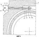
Фиг.2 - соединение подшипника с масляной пленкой с подключаемым блоком,Figure 2 - connection of the bearing with an oil film with a plug-in unit,
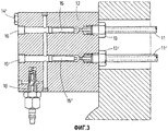
Фиг.3 - подключаемый блок с обратным клапаном.Figure 3 - plug-in unit with check valve.
На фиг.1 показан подшипник с масляной пленкой, который установлен на подушке 2 и состоит из буксы 3 шейки, которая расположена на шейке 4 валка, и вкладыша 5 подшипника, который установлен в подушке 2.Figure 1 shows the bearing with an oil film, which is mounted on the pillow 2 and consists of a journal 3 of the neck, which is located on the neck 4 of the roll, and the bearing shell 5, which is installed in the pillow 2.
Во вкладыше 5 подшипника расположены два отверстия 6, 6', которые частично лежат одно за другим и идут от внешнего края 7 вкладыша 5 подшипника к радиальным отверстиям 8, 8', которые заканчиваются в гидростатических карманах 9, 9'.Two holes 6, 6 'are located in the bearing shell 5, which partially lie one after the other and extend from the outer edge 7 of the bearing shell 5 to the radial holes 8, 8', which end in hydrostatic pockets 9, 9 '.
На вкладыше 5 подшипника предусмотрены соединительные элементы 10, 10' высокого давления, на которых смонтированы жесткие магистрали 11, 11', которые идут к подключаемому блоку 12 и здесь также закреплены с помощью соединительных элементов 13, 13' высокого давления (см. фиг.2). Подключаемый блок 12 с помощью винтов 14, 14' закреплен на подушке 2.On the bearing shell 5, high-
На фиг.3 показаны магистрали 11, 11', которые через соединительные элементы 13, 13' подсоединены к подключаемому блоку 12. В подключаемом блоке 12 расположены дроссели 15, 15'. Дроссели после удаления заглушек 16, 16', доступных без каких-либо затруднений, могут быть легко извлечены для целей контроля или замены из подключаемого блока 12. В подключаемом блоке 12 может быть предусмотрено достаточно места для обеспечения возможности применения дросселей, которые имеют не такую тонкую конструкцию, которая применялась до сих пор. Следует отметить, что предусмотрено только два дросселя. Если вкладыш 5 подшипника поворачивается на 180°, то должны рассоединиться только соединительные элементы 10, 10' высокого давления. После рассоединения крепежного болта 17 (см. фиг.1) вкладыш 5 подшипника может повернуться на 180°, и повернувшиеся на 180° отверстия соединяются с соединительными элементами 10, 10' высокого давления. Благодаря этому достигается экономия двух дросселей. Таким образом, вместо принятых до сих пор четырех дросселей теперь необходимо наличие только двух дросселей.Figure 3 shows the
На фиг.3 представлен обратный клапан 18, который также закреплен на блоке 12, при этом к нему имеется легкий доступ. Благодаря легкому доступу исключаются ошибки при монтаже обратного клапана 18.Figure 3 presents the
Claims (6)
Applications Claiming Priority (2)
| Application Number | Priority Date | Filing Date | Title |
|---|---|---|---|
| DE10336894A DE10336894A1 (en) | 2003-08-08 | 2003-08-08 | Oil film bearing for roll neck with hydrostatic support |
| DE10336894.9 | 2003-08-08 |
Publications (2)
| Publication Number | Publication Date |
|---|---|
| RU2006106921A RU2006106921A (en) | 2006-07-10 |
| RU2339853C2 true RU2339853C2 (en) | 2008-11-27 |
Family
ID=34177465
Family Applications (1)
| Application Number | Title | Priority Date | Filing Date |
|---|---|---|---|
| RU2006106921/11A RU2339853C2 (en) | 2003-08-08 | 2004-07-07 | Oil-lubed bearing for shaft journal |
Country Status (13)
| Country | Link |
|---|---|
| US (1) | US7484891B2 (en) |
| EP (1) | EP1651876B1 (en) |
| JP (1) | JP4559421B2 (en) |
| KR (1) | KR101086665B1 (en) |
| CN (1) | CN100408878C (en) |
| AT (1) | ATE443815T1 (en) |
| BR (1) | BRPI0413416A (en) |
| DE (2) | DE10336894A1 (en) |
| ES (1) | ES2331133T3 (en) |
| PL (1) | PL1651876T3 (en) |
| RU (1) | RU2339853C2 (en) |
| WO (1) | WO2005017377A1 (en) |
| ZA (1) | ZA200510363B (en) |
Cited By (1)
| Publication number | Priority date | Publication date | Assignee | Title |
|---|---|---|---|---|
| RU2691004C1 (en) * | 2015-11-23 | 2019-06-07 | Смс Груп Гмбх | Volumetric flow control valve |
Families Citing this family (9)
| Publication number | Priority date | Publication date | Assignee | Title |
|---|---|---|---|---|
| US8246250B2 (en) * | 2008-01-11 | 2012-08-21 | Sms Siemag Aktiengesellschaft | Bearing arrangement |
| ITUD20090062A1 (en) * | 2009-03-26 | 2010-09-27 | Danieli Off Mecc | CONNECTION COMPONENT FOR OIL FILM BEARINGS |
| DE102010029492A1 (en) * | 2010-05-31 | 2011-12-01 | Voith Patent Gmbh | Roller and method for avoiding their vibrations |
| US9016099B2 (en) | 2011-09-29 | 2015-04-28 | Siemens Industry, Inc. | Hybrid hydrodynamic and hydrostatic bearing bushing and lubrication system for rolling mill |
| DE102012209828A1 (en) | 2012-06-12 | 2013-12-12 | Sms Siemag Ag | roll arrangement |
| DE102012209831A1 (en) | 2012-06-12 | 2013-12-12 | Sms Siemag Ag | roll arrangement |
| CN102840244B (en) * | 2012-08-31 | 2015-04-08 | 太原重工股份有限公司 | Bushing locating device for oil film bearing |
| CN112045204A (en) * | 2020-08-25 | 2020-12-08 | 浙江斯特隆科技有限公司 | Heavy-duty hydraulic type shifting formwork arm |
| DE102021205276A1 (en) * | 2021-05-21 | 2021-07-22 | Sms Group Gmbh | Journal bushing as part of an oil film bearing |
Citations (4)
| Publication number | Priority date | Publication date | Assignee | Title |
|---|---|---|---|---|
| US3453031A (en) * | 1967-04-06 | 1969-07-01 | Morgan Construction Co | Bearing assembly |
| SU412409A1 (en) * | 1971-10-15 | 1974-01-25 | И. И. Бродецкий , М. А. Шиманович Московский станкоинструментальный институт | HYDROSTATIC SUPPORT |
| US3998502A (en) * | 1972-10-26 | 1976-12-21 | Skf Industrial Trading And Development Company, B.V. | Fluid bearing system |
| RU2117829C1 (en) * | 1996-01-04 | 1998-08-20 | Мурадов Захир Ахмедович | Locomotive motor-axial plain bearing with capillary lubrication system |
Family Cites Families (12)
| Publication number | Priority date | Publication date | Assignee | Title |
|---|---|---|---|---|
| DE242456C (en) | ||||
| DE2252495A1 (en) * | 1972-10-26 | 1974-05-02 | Skf Kugellagerfabriken Gmbh | HYDRO OR AEROSTATIC BEARING |
| JPS57195918A (en) | 1981-05-29 | 1982-12-01 | Hitachi Ltd | Bearing for neck of roll |
| DD242456A1 (en) * | 1985-10-31 | 1987-01-28 | Leipzig Werkstoffpruefmasch | HYDROSTATIC BEARING WITH OPTIMIZED WEARING CHARACTERISTICS |
| US4944609A (en) * | 1987-03-30 | 1990-07-31 | Morgan Construction Company | Oil film bearing and bushing |
| US4772137A (en) * | 1987-03-30 | 1988-09-20 | Morgan Construction Company | Oil film bearing and bushing |
| DE3918989C1 (en) * | 1989-06-10 | 1990-12-13 | Eduard Kuesters Maschinenfabrik Gmbh & Co Kg, 4150 Krefeld, De | |
| US5000584A (en) * | 1990-03-02 | 1991-03-19 | Morgan Construction Company | Bushing for oil film bearing |
| CN2176856Y (en) * | 1993-10-18 | 1994-09-14 | 张锡圣 | High-precision dynamical-statical pressure oil film bearing numerically controlled machine tool |
| EP0812995A3 (en) * | 1996-06-04 | 1998-09-02 | FÜRSTLICH HOHENZOLLERNSCHE WERKE LAUCHERTHAL GMBH & CO. | Aerostatic bearing with holding structure |
| JP4134541B2 (en) * | 2000-09-25 | 2008-08-20 | 株式会社ジェイテクト | Fluid bearing |
| JP4161651B2 (en) | 2001-09-26 | 2008-10-08 | 株式会社ジェイテクト | Fluid bearing |
-
2003
- 2003-08-08 DE DE10336894A patent/DE10336894A1/en not_active Withdrawn
-
2004
- 2004-07-07 RU RU2006106921/11A patent/RU2339853C2/en not_active IP Right Cessation
- 2004-07-07 ES ES04740748T patent/ES2331133T3/en not_active Expired - Lifetime
- 2004-07-07 DE DE502004010118T patent/DE502004010118D1/en not_active Expired - Lifetime
- 2004-07-07 EP EP04740748A patent/EP1651876B1/en not_active Expired - Lifetime
- 2004-07-07 US US10/567,895 patent/US7484891B2/en not_active Expired - Lifetime
- 2004-07-07 PL PL04740748T patent/PL1651876T3/en unknown
- 2004-07-07 BR BRPI0413416-8A patent/BRPI0413416A/en active Search and Examination
- 2004-07-07 JP JP2006522247A patent/JP4559421B2/en not_active Expired - Fee Related
- 2004-07-07 CN CNB2004800227575A patent/CN100408878C/en not_active Expired - Fee Related
- 2004-07-07 KR KR1020067002605A patent/KR101086665B1/en not_active Expired - Fee Related
- 2004-07-07 WO PCT/EP2004/007435 patent/WO2005017377A1/en not_active Ceased
- 2004-07-07 AT AT04740748T patent/ATE443815T1/en active
-
2005
- 2005-12-21 ZA ZA200510363A patent/ZA200510363B/en unknown
Patent Citations (4)
| Publication number | Priority date | Publication date | Assignee | Title |
|---|---|---|---|---|
| US3453031A (en) * | 1967-04-06 | 1969-07-01 | Morgan Construction Co | Bearing assembly |
| SU412409A1 (en) * | 1971-10-15 | 1974-01-25 | И. И. Бродецкий , М. А. Шиманович Московский станкоинструментальный институт | HYDROSTATIC SUPPORT |
| US3998502A (en) * | 1972-10-26 | 1976-12-21 | Skf Industrial Trading And Development Company, B.V. | Fluid bearing system |
| RU2117829C1 (en) * | 1996-01-04 | 1998-08-20 | Мурадов Захир Ахмедович | Locomotive motor-axial plain bearing with capillary lubrication system |
Cited By (1)
| Publication number | Priority date | Publication date | Assignee | Title |
|---|---|---|---|---|
| RU2691004C1 (en) * | 2015-11-23 | 2019-06-07 | Смс Груп Гмбх | Volumetric flow control valve |
Also Published As
| Publication number | Publication date |
|---|---|
| ES2331133T3 (en) | 2009-12-22 |
| US7484891B2 (en) | 2009-02-03 |
| KR20060061817A (en) | 2006-06-08 |
| DE10336894A1 (en) | 2005-03-10 |
| US20080175523A1 (en) | 2008-07-24 |
| RU2006106921A (en) | 2006-07-10 |
| KR101086665B1 (en) | 2011-11-24 |
| ATE443815T1 (en) | 2009-10-15 |
| EP1651876A1 (en) | 2006-05-03 |
| BRPI0413416A (en) | 2006-10-10 |
| ZA200510363B (en) | 2006-09-27 |
| CN1833113A (en) | 2006-09-13 |
| PL1651876T3 (en) | 2010-02-26 |
| WO2005017377A1 (en) | 2005-02-24 |
| CN100408878C (en) | 2008-08-06 |
| DE502004010118D1 (en) | 2009-11-05 |
| JP4559421B2 (en) | 2010-10-06 |
| EP1651876B1 (en) | 2009-09-23 |
| JP2007533916A (en) | 2007-11-22 |
Similar Documents
| Publication | Publication Date | Title |
|---|---|---|
| RU2339853C2 (en) | Oil-lubed bearing for shaft journal | |
| US3975123A (en) | Shaft seals for a screw compressor | |
| US3887245A (en) | Pivoted pad bearing apparatus and method for bidirectional rotation | |
| KR100606994B1 (en) | A screw compressor injected with water | |
| RU2617802C2 (en) | Hybrid hydrodynamic and hydrostatic bearing bushing and lubrication system for rolling mill | |
| WO1994015100A1 (en) | Rotary screw compressor with shaft seal | |
| KR100352806B1 (en) | Double rocking pad journal bearing | |
| US20190353543A1 (en) | Axial thrust force balancing apparatus for an integrally geared compressor | |
| WO2020156089A1 (en) | Deep water pump having pressure compensation function | |
| US20020140177A1 (en) | Seal | |
| US6578603B1 (en) | Swivel apparatus | |
| CZ297939B6 (en) | Device for compensating axial shift in turbine machines | |
| US6857872B2 (en) | Device for loading a shaft furnace | |
| AU2013282771A1 (en) | Improvements in fluid bearings | |
| EP0203674A1 (en) | Journal mounted rotary joint | |
| EP2661571B1 (en) | Check valve for a pipe section | |
| US10563641B2 (en) | Distribution device for hydraulic machine | |
| RU2347961C1 (en) | Gasostatic radial-thrust bearing with shaft position adjuster | |
| US7727133B2 (en) | Sealing device | |
| KR200462850Y1 (en) | Rotary joint | |
| RU2336442C1 (en) | Water plain bearing support | |
| US3869774A (en) | Fluid bearing table roll | |
| US1558055A (en) | Pump | |
| KR200397942Y1 (en) | A rotary joint | |
| WO2003004919A1 (en) | Journal bearing mounted hub seal rotary joint |
Legal Events
| Date | Code | Title | Description |
|---|---|---|---|
| MM4A | The patent is invalid due to non-payment of fees |
Effective date: 20180708 |