RU2337223C2 - Counterforce and transom separating element for multiple glass - Google Patents
Counterforce and transom separating element for multiple glass Download PDFInfo
- Publication number
- RU2337223C2 RU2337223C2 RU2005101740A RU2005101740A RU2337223C2 RU 2337223 C2 RU2337223 C2 RU 2337223C2 RU 2005101740 A RU2005101740 A RU 2005101740A RU 2005101740 A RU2005101740 A RU 2005101740A RU 2337223 C2 RU2337223 C2 RU 2337223C2
- Authority
- RU
- Russia
- Prior art keywords
- binding
- heat
- insulating
- glasses
- spacer
- Prior art date
Links
Images


Classifications
-
- E—FIXED CONSTRUCTIONS
- E06—DOORS, WINDOWS, SHUTTERS, OR ROLLER BLINDS IN GENERAL; LADDERS
- E06B—FIXED OR MOVABLE CLOSURES FOR OPENINGS IN BUILDINGS, VEHICLES, FENCES OR LIKE ENCLOSURES IN GENERAL, e.g. DOORS, WINDOWS, BLINDS, GATES
- E06B3/00—Window sashes, door leaves, or like elements for closing wall or like openings; Layout of fixed or moving closures, e.g. windows in wall or like openings; Features of rigidly-mounted outer frames relating to the mounting of wing frames
- E06B3/66—Units comprising two or more parallel glass or like panes permanently secured together
- E06B3/663—Elements for spacing panes
- E06B3/667—Connectors therefor
-
- E—FIXED CONSTRUCTIONS
- E06—DOORS, WINDOWS, SHUTTERS, OR ROLLER BLINDS IN GENERAL; LADDERS
- E06B—FIXED OR MOVABLE CLOSURES FOR OPENINGS IN BUILDINGS, VEHICLES, FENCES OR LIKE ENCLOSURES IN GENERAL, e.g. DOORS, WINDOWS, BLINDS, GATES
- E06B3/00—Window sashes, door leaves, or like elements for closing wall or like openings; Layout of fixed or moving closures, e.g. windows in wall or like openings; Features of rigidly-mounted outer frames relating to the mounting of wing frames
- E06B3/66—Units comprising two or more parallel glass or like panes permanently secured together
- E06B3/663—Elements for spacing panes
-
- E—FIXED CONSTRUCTIONS
- E06—DOORS, WINDOWS, SHUTTERS, OR ROLLER BLINDS IN GENERAL; LADDERS
- E06B—FIXED OR MOVABLE CLOSURES FOR OPENINGS IN BUILDINGS, VEHICLES, FENCES OR LIKE ENCLOSURES IN GENERAL, e.g. DOORS, WINDOWS, BLINDS, GATES
- E06B3/00—Window sashes, door leaves, or like elements for closing wall or like openings; Layout of fixed or moving closures, e.g. windows in wall or like openings; Features of rigidly-mounted outer frames relating to the mounting of wing frames
- E06B3/66—Units comprising two or more parallel glass or like panes permanently secured together
- E06B3/6604—Units comprising two or more parallel glass or like panes permanently secured together comprising false glazing bars or similar decorations between the panes
-
- E—FIXED CONSTRUCTIONS
- E06—DOORS, WINDOWS, SHUTTERS, OR ROLLER BLINDS IN GENERAL; LADDERS
- E06B—FIXED OR MOVABLE CLOSURES FOR OPENINGS IN BUILDINGS, VEHICLES, FENCES OR LIKE ENCLOSURES IN GENERAL, e.g. DOORS, WINDOWS, BLINDS, GATES
- E06B3/00—Window sashes, door leaves, or like elements for closing wall or like openings; Layout of fixed or moving closures, e.g. windows in wall or like openings; Features of rigidly-mounted outer frames relating to the mounting of wing frames
- E06B3/04—Wing frames not characterised by the manner of movement
- E06B3/06—Single frames
- E06B3/08—Constructions depending on the use of specified materials
- E06B3/12—Constructions depending on the use of specified materials of metal
- E06B3/14—Constructions depending on the use of specified materials of metal of special cross-section
- E06B3/16—Hollow frames of special construction, e.g. made of folded sheet metal or of two or more section parts connected together
- E06B3/163—Hollow frames of special construction, e.g. made of folded sheet metal or of two or more section parts connected together with a filled cavity
-
- E—FIXED CONSTRUCTIONS
- E06—DOORS, WINDOWS, SHUTTERS, OR ROLLER BLINDS IN GENERAL; LADDERS
- E06B—FIXED OR MOVABLE CLOSURES FOR OPENINGS IN BUILDINGS, VEHICLES, FENCES OR LIKE ENCLOSURES IN GENERAL, e.g. DOORS, WINDOWS, BLINDS, GATES
- E06B3/00—Window sashes, door leaves, or like elements for closing wall or like openings; Layout of fixed or moving closures, e.g. windows in wall or like openings; Features of rigidly-mounted outer frames relating to the mounting of wing frames
- E06B3/66—Units comprising two or more parallel glass or like panes permanently secured together
- E06B3/663—Elements for spacing panes
- E06B3/66304—Discrete spacing elements, e.g. for evacuated glazing units
-
- E—FIXED CONSTRUCTIONS
- E06—DOORS, WINDOWS, SHUTTERS, OR ROLLER BLINDS IN GENERAL; LADDERS
- E06B—FIXED OR MOVABLE CLOSURES FOR OPENINGS IN BUILDINGS, VEHICLES, FENCES OR LIKE ENCLOSURES IN GENERAL, e.g. DOORS, WINDOWS, BLINDS, GATES
- E06B3/00—Window sashes, door leaves, or like elements for closing wall or like openings; Layout of fixed or moving closures, e.g. windows in wall or like openings; Features of rigidly-mounted outer frames relating to the mounting of wing frames
- E06B3/66—Units comprising two or more parallel glass or like panes permanently secured together
- E06B3/663—Elements for spacing panes
- E06B3/66309—Section members positioned at the edges of the glazing unit
- E06B3/66314—Section members positioned at the edges of the glazing unit of tubular shape
- E06B3/66319—Section members positioned at the edges of the glazing unit of tubular shape of rubber, plastics or similar materials
-
- E—FIXED CONSTRUCTIONS
- E06—DOORS, WINDOWS, SHUTTERS, OR ROLLER BLINDS IN GENERAL; LADDERS
- E06B—FIXED OR MOVABLE CLOSURES FOR OPENINGS IN BUILDINGS, VEHICLES, FENCES OR LIKE ENCLOSURES IN GENERAL, e.g. DOORS, WINDOWS, BLINDS, GATES
- E06B3/00—Window sashes, door leaves, or like elements for closing wall or like openings; Layout of fixed or moving closures, e.g. windows in wall or like openings; Features of rigidly-mounted outer frames relating to the mounting of wing frames
- E06B3/66—Units comprising two or more parallel glass or like panes permanently secured together
- E06B3/663—Elements for spacing panes
- E06B3/66309—Section members positioned at the edges of the glazing unit
- E06B2003/6639—Section members positioned at the edges of the glazing unit sinuous
-
- Y—GENERAL TAGGING OF NEW TECHNOLOGICAL DEVELOPMENTS; GENERAL TAGGING OF CROSS-SECTIONAL TECHNOLOGIES SPANNING OVER SEVERAL SECTIONS OF THE IPC; TECHNICAL SUBJECTS COVERED BY FORMER USPC CROSS-REFERENCE ART COLLECTIONS [XRACs] AND DIGESTS
- Y10—TECHNICAL SUBJECTS COVERED BY FORMER USPC
- Y10T—TECHNICAL SUBJECTS COVERED BY FORMER US CLASSIFICATION
- Y10T428/00—Stock material or miscellaneous articles
- Y10T428/24—Structurally defined web or sheet [e.g., overall dimension, etc.]
- Y10T428/24744—Longitudinal or transverse tubular cavity or cell
-
- Y—GENERAL TAGGING OF NEW TECHNOLOGICAL DEVELOPMENTS; GENERAL TAGGING OF CROSS-SECTIONAL TECHNOLOGIES SPANNING OVER SEVERAL SECTIONS OF THE IPC; TECHNICAL SUBJECTS COVERED BY FORMER USPC CROSS-REFERENCE ART COLLECTIONS [XRACs] AND DIGESTS
- Y10—TECHNICAL SUBJECTS COVERED BY FORMER USPC
- Y10T—TECHNICAL SUBJECTS COVERED BY FORMER US CLASSIFICATION
- Y10T428/00—Stock material or miscellaneous articles
- Y10T428/249921—Web or sheet containing structurally defined element or component
- Y10T428/249953—Composite having voids in a component [e.g., porous, cellular, etc.]
- Y10T428/249982—With component specified as adhesive or bonding agent
Landscapes
- Engineering & Computer Science (AREA)
- Civil Engineering (AREA)
- Structural Engineering (AREA)
- Securing Of Glass Panes Or The Like (AREA)
- Joining Of Glass To Other Materials (AREA)
Abstract
Description
По данной заявке испрашивается приоритет согласно заявке США 60/393593 от 03.07.2002, включенной в настоящее описание в качестве ссылки.This application claims priority according to US application 60/393593 dated 07/03/2002, incorporated herein by reference.
Область техники, к которой относится изобретениеFIELD OF THE INVENTION
Изобретение относится в основном к теплоизолирующим стеклопакетам, которые могут использоваться в конструкциях окон и дверей. В более узком аспекте оно относится к распорному элементу и разделительному элементу переплета для стеклопакетов. Более конкретно, изобретение относится к конструкции распорного элемента и разделительного элемента переплета, а также к использованию этих элементов в стеклопакетах.The invention relates generally to insulating glass units that can be used in the construction of windows and doors. In a narrower aspect, it relates to a spacer and a spacer for binding for double-glazed windows. More specifically, the invention relates to the design of a spacer element and a spacer element for binding, as well as to the use of these elements in glass units.
Уровень техникиState of the art
Традиционные окна содержат отдельные стекла, разделенные деревянными элементами переплета, именуемыми горбыльками. Хотя такие окна привлекательны на вид и функционируют в течение многих лет, они относительно дороги в изготовлении. Стоимость особенно высока, если потребитель желает иметь теплоизолирующее окно с отстоящими друг от друга стеклами, герметично соединенными по периметру распорным элементом. Для одного окна с двенадцатью стеклами требуется двенадцать распорных элементов, двадцать четыре стекла и точно подогнанная решетка из разделительных элементов переплета. Таким образом, хотя потребители нуждаются в эстетических свойствах традиционных окон, делящих поступающий свет, большинство из них не готовы платить за окно с настоящим разделительным переплетом.Traditional windows contain individual glass, separated by wooden binding elements, called bowls. Although these windows are attractive in appearance and function for many years, they are relatively expensive to manufacture. The cost is especially high if the consumer wants to have a heat-insulating window with spaced apart glasses, hermetically connected around the perimeter of the spacer element. For one window with twelve glasses, twelve spacer elements, twenty-four glasses and a finely matched grille of binding elements are required. Thus, although consumers need the aesthetic properties of traditional windows that divide incoming light, most of them are not willing to pay for a window with a real dividing cover.
Теплоизолирующие окна содержат по меньшей мере два стекла, отделенные друг от друга распорным элементом для образования герметичной полости, обеспечивающей теплоизолирующие свойства. Эти окна наиболее эффективно изготавливают с двумя большими стеклами, отделенными друг от друга единым распорным элементом, проходящим по периметру стекол. Предлагались различные решения по приданию окнам вида окна с разделительным переплетом. В одном из решений предусматривалось размещение решетки переплета между стеклами. В другом решении предусматривалось размещение решетки на наружной поверхности одного или обоих стекол.The heat-insulating windows contain at least two glasses, separated from each other by a spacer element to form an airtight cavity providing heat-insulating properties. These windows are most effectively made with two large glasses, separated from each other by a single spacer element, passing along the perimeter of the glasses. Various solutions have been proposed to give windows a window with a dividing cover. One of the solutions provided for the placement of a grating between the glasses. Another solution provided for the placement of the lattice on the outer surface of one or both glasses.
В патенте США №5345743 раскрыто еще одно решение, в котором три разделительных элемента переплета используются для создания внешнего вида переплета. В конструкции использован один внутренний разделительный элемент переплета, прикрепленный к одному стеклу, и два наружных разделительных элемента переплета, расположенные снаружи стекла. Наружные элементы переплета выровнены по внутреннему элементу переплета для создания внешнего вида традиционного переплета.US Pat. No. 5,345,743 discloses yet another solution in which the three spacer elements of the binding are used to create the appearance of the binding. The design used one internal binder separation element attached to one glass and two external binder separation elements located outside the glass. The outer binding elements are aligned with the inner binding element to create the appearance of a traditional binding.
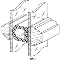
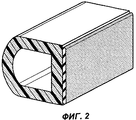
Известный из уровня техники пустотелый разделительный элемент переплета представлен на фиг.1 и 2. Известный элемент переплета имеет тонкие наружные стенки, образующие обширную полость D-образной формы. Большая D-образная полость нежелательна, так как она вызывает смятие и перекос элемента переплета при его свертывании в рулон для хранения. Таким образом, элемент данной конструкции не может быть свернут в удобную форму для хранения и транспортировки. Кроме того, он сминается или перекашивается под углом при запрессовке между внутренними поверхностями стекол и нарушает эстетический вид переплета.BACKGROUND OF THE INVENTION A hollow binder separation member known in the art is shown in FIGS. 1 and 2. The known binding member has thin outer walls forming an extensive D-shaped cavity. A large D-shaped cavity is undesirable, since it causes wrinkling and skewing of the binding element when it is rolled into a roll for storage. Thus, an element of this design cannot be folded into a convenient shape for storage and transportation. In addition, it crumpled or skewed at an angle when pressing between the inner surfaces of the glass and violates the aesthetic appearance of the binding.
Раскрытие изобретенияDisclosure of invention
Изобретение предлагает разделительный элемент переплета, выполненный с возможностью прикрепления к внутренним поверхностям противоположных стекол для имитации элемента традиционного переплета. Изобретение предлагает компенсационные элементы, которые позволяют крепить элемент переплета к обеим внутренним поверхностям. Компенсационные элементы предотвращают отслаивание разделительного элемента переплета при расширении и сужении стеклопакета. Предложены и раскрыты различные примеры выполнения компенсационных элементов.The invention provides a binding spacer that is capable of attaching opposing glasses to the inner surfaces to simulate a traditional binding spacer. The invention provides compensation elements that allow the binding element to be fastened to both internal surfaces. Compensation elements prevent peeling of the binder separator when expanding and narrowing the glass. Various examples of the implementation of compensation elements are proposed and disclosed.
В соответствии с изобретением предусмотрен также разделительный элемент переплета с внутренними проходами, которые образуют теплоизолирующие полости. Эти полости выполнены с обеспечением сохранения конструктивной прочности элемента переплета при его упаковке, транспортировке и монтаже.In accordance with the invention, there is also provided a spacer element for binding with internal passages that form heat-insulating cavities. These cavities are designed to maintain the structural strength of the binding element during its packaging, transportation and installation.
В соответствии с изобретением предусмотрен распорный элемент, снабженный проходом, который повышает его теплоизолирующие свойства. Конфигурация прохода обеспечивает прочность распорного элемента на сжатие. Конфигурация прохода может также способствовать регулированию распорного элемента в соответствии с перемещением стекол.In accordance with the invention, a spacer element is provided, provided with a passage that improves its heat-insulating properties. The passage configuration provides compressive strength to the spacer. The passage configuration can also help to adjust the spacer according to the movement of the windows.
Краткое описание чертежейBrief Description of the Drawings
Фиг.1 и 2 изображают известный из уровня техники элемент переплета D-образной формы,1 and 2 depict a prior art binding element of a D-shape,
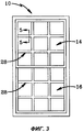
фиг.3 изображает на виде спереди известное из уровня техники окно, имитирующее окно с разделительным переплетом, который состоит из верхней и нижней решеток, образованных разделительными элементами, причем каждая решетка образована двумя вертикальными и двумя горизонтальными элементами переплета,figure 3 depicts a front view of a prior art window that simulates a window with a dividing binder, which consists of upper and lower gratings formed by dividing elements, each grating is formed by two vertical and two horizontal binding elements,
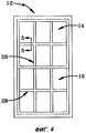
фиг.4 изображает на виде, подобном фиг.3, известное из уровня техники окно, имеющее верхнюю и нижнюю решетки разделительного переплета, причем каждая решетка образована двумя вертикальными и одним горизонтальным элементами переплета,figure 4 depicts in a view similar to figure 3, known from the prior art, the window having the upper and lower lattice separating binding, and each lattice is formed by two vertical and one horizontal binding elements,
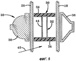
фиг.5 изображает окно в разрезе по линии 5-5 на фиг.3 или 4,figure 5 depicts a window in section along the line 5-5 in figure 3 or 4,
фиг.6 изображает разделительный элемент переплета по изобретению в одном примере выполнения, в котором он содержит продольные проходы,Fig.6 depicts the separating element of the binding according to the invention in one embodiment, in which it contains longitudinal passages,
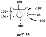
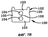
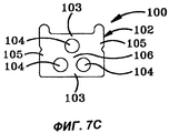
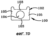
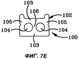
фиг.7А-7Е изображают разделительный элемент переплета по изобретению в других примерах выполнения,figa-7E depict the spacer element of the binding according to the invention in other examples,
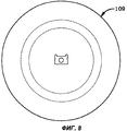
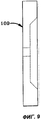
фиг.8 изображает на виде спереди экструзионную головку, используемую для формования разделительного элемента переплета,Fig. 8 is a front view of an extrusion die used to form a binding spacer,
фиг.9 изображает экструзионную головку на виде сбоку,Fig.9 depicts the extrusion head in side view,
фиг.10 изображает разделительный элемент переплета по изобретению в другом примере выполнения, в котором он содержит один проход и отличается от примеров выполнения по фиг.7А-7Е формой поперечного сечения элемента и прохода,figure 10 depicts the separating element of the binding according to the invention in another embodiment, in which it contains one passage and differs from the examples in figures 7A-7E in the cross-sectional shape of the element and the passage,
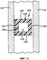
фиг.11 изображает разделительный элемент переплета по изобретению в следующем примере выполнения, в котором он содержит один проход и отличается от примеров выполнения по фиг.7А-7Е формой поперечного сечения элемента и прохода,11 depicts the separating element of the binding according to the invention in the following exemplary embodiment, in which it contains one passage and differs from the examples in FIGS. 7A-7E in the cross-sectional shape of the element and the passage,
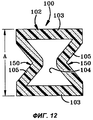
фиг.12 изображает в разрезе разделительный элемент переплета в следующем примере выполнения, в котором он содержит противолежащие компенсационные элементы и показан на этапе до нанесения клея, когда элемент переплета имеет высоту А, причем тело элемента переплета изготовлено из пенопласта и может быть снабжено влагопоглотителем,12 depicts a cross-section of a binder separation element in the following exemplary embodiment, in which it contains opposite compensation elements and is shown in the step before applying glue when the binder element has a height A, the body of the binding element being made of foam and may be equipped with a desiccant,
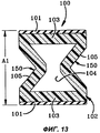
фиг.13 изображает в разрезе разделительный элемент переплета по фиг.12 после нанесения клея на основания,Fig.13 depicts in section a separating element of the binding of Fig.12 after applying glue to the base,
фиг.14 изображает разделительный элемент переплета, наложенный на внутреннюю поверхность первого стекла,Fig.14 depicts the separating element of the binding superimposed on the inner surface of the first glass,
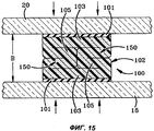
фиг.15 изображает второе стекло, которое накладывают на разделительный элемент переплета и прижимают вниз для надежного прилипания клея к поверхностям стекла, при этом элемент переплета сжимается до толщины В, меньшей, чем толщина А и А1, а конструкция элемента переплета предотвращает его продавливание и обеспечивает легкую установку,Fig depicts a second glass, which is applied to the separating element of the binding and pressed down for reliable adhesion of glue to the surfaces of the glass, while the binding element is compressed to a thickness B, less than the thickness A and A1, and the design of the binding element prevents its punching and provides easy installation
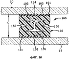
фиг.16 изображает стеклопакет в положении покоя при нейтральном давлении, в котором элемент переплета сжат до высоты С, большей, чем В, но меньшей, чем А или А1, при этом компенсационные элементы выполнены в виде щелей, которые могут расширяться при удалении стекол друг от друга,Fig.16 depicts a double-glazed window in a resting position at neutral pressure, in which the binding element is compressed to a height C greater than B but less than A or A1, while the compensation elements are made in the form of slots that can expand when the glasses are removed from friend,
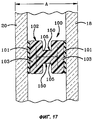
фиг.17 изображает разделительный элемент переплета в следующем примере выполнения с другими компенсационными элементами, при этом элемент переплета слегка сжат стеклами при нейтральном давлении, а конструкция элемента переплета предотвращает его продавливание и обеспечивает легкую установку,Fig depicts the separating element of the binding in the following example, with other compensation elements, while the binding element is slightly compressed with glasses at neutral pressure, and the design of the binding element prevents its punching and provides easy installation,
фиг.18 изображает разделительный элемент переплета по фиг.17 в расправленном положении, при котором размер В больше А,Fig.18 depicts the separating element of the binding of Fig.17 in the unfolded position, in which the size is greater than A,
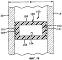
фиг.19 изображает в разрезе разделительный элемент переплета с противолежащими компенсационными элементами до нанесения клея на основания, когда элемент переплета имеет высоту А, а его тело изготовлено из пенопласта и может быть снабжено влагопоглотителем,Fig.19 depicts a cross-section of the separating element of the binding with opposite compensation elements before applying glue to the base, when the binding element has a height A, and its body is made of foam and can be equipped with a desiccant,
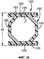
фиг.20 изображает в разрезе разделительный элемент переплета по фиг.19 после нанесения клея на основания,Fig.20 depicts in section a separating element of the binding of Fig.19 after applying glue to the base,
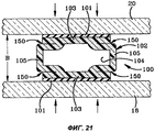
фиг.21 изображает стекла, наложенные на разделительный элемент переплета и прижатые к нему для надежного прилипания клея к поверхностям стекол, при этом элемент переплета сжимается до толщины В, меньшей, чем толщина А и А1, а конструкция элемента переплета предотвращает его продавливание и обеспечивает легкую установку,Fig. 21 depicts glasses superimposed on the binding element and pressed to it for reliable adhesion of glue to the surfaces of the glasses, wherein the binding element is compressed to a thickness B less than thickness A and A1, and the design of the binding element prevents its punching and provides easy installation
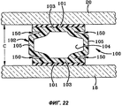
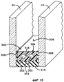
фиг.22 изображает стеклопакет в положении покоя при нейтральном давлении, в котором разделительный элемент переплета сжат до высоты С, большей, чем В, но меньшей, чем А или А1, при этом компенсационные элементы выполнены в виде щелей, которые могут расширяться при удалении стекол друг от друга,Fig depicts a double-glazed window in a resting position at neutral pressure, in which the binder separator is compressed to a height C greater than B but less than A or A1, while the compensation elements are made in the form of slots that can expand when the glasses are removed apart
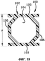
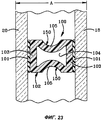
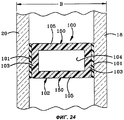
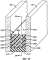
фиг.23 изображает разделительный элемент переплета в альтернативном примере выполнения с другими компенсационными элементами, при этом элемент переплета слегка сжат стеклами при нейтральном давлении, а конструкция элемента переплета предотвращает его продавливание и обеспечивает легкую установку,23 depicts a binder spacer in an alternative embodiment with other compensation elements, wherein the binder is slightly squeezed with glasses at neutral pressure, and the design of the binder prevents its punching and provides easy installation,
фиг.24 изображает разделительный элемент переплета по фиг.23 в расправленном положении, при котором размер В больше А,Fig.24 depicts the separating element of the binding of Fig.23 in the unfolded position, in which the size is greater than A,
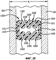
фиг.25 изображает разделительный элемент переплета в альтернативном примере выполнения с другими компенсационными элементами, при этом элемент переплета слегка сжат стеклами при нейтральном давлении, а конструкция элемента переплета предотвращает его продавливание и обеспечивает легкую установку,Fig.25 depicts the separating element of the binding in an alternative embodiment with other compensation elements, while the binding element is slightly compressed with glasses at neutral pressure, and the design of the binding element prevents its punching and provides easy installation,
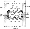
фиг.26 изображает разделительный элемент переплета по фиг.25 в расправленном положении, при котором размер В больше А,Fig.26 depicts the separating element of the binding of Fig.25 in the unfolded position, in which the size is greater than A,
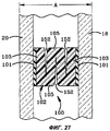
фиг.27 изображает разделительный элемент переплета в альтернативном примере выполнения с другими компенсационными элементами, при этом элемент переплета слегка сжат стеклами при нейтральном давлении, а конструкция элемента переплета предотвращает его продавливание и обеспечивает легкую установку,Fig.27 depicts the separating element of the binding in an alternative embodiment with other compensation elements, while the binding element is slightly compressed with glasses at neutral pressure, and the design of the binding element prevents its punching and provides easy installation,
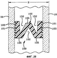
фиг.28 изображает разделительный элемент переплета по фиг.27 в расправленном положении, при котором размер В больше А,Fig.28 depicts the separating element of the binding of Fig.27 in the unfolded position, in which the size is greater than A,
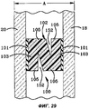
фиг.29 изображает разделительный элемент переплета в альтернативном примере выполнения с другими компенсационными элементами, при этом элемент переплета слегка сжат стеклами при нейтральном давлении, а конструкция элемента переплета предотвращает его продавливание и обеспечивает легкую установку,Fig.29 depicts the separating element of the binding in an alternative embodiment with other compensation elements, while the binding element is slightly compressed with glasses at neutral pressure, and the design of the binding element prevents its punching and provides easy installation,
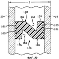
фиг.30 изображает элемент переплета по фиг.29 в расправленном положении, при котором размер В больше А,Fig.30 depicts the binding element of Fig.29 in the unfolded position, in which the size is greater than A,
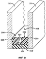
фиг.31 изображает распорный элемент, содержащий теплоизолирующую полость, проходящую в продольном направлении внутри тела распорного элемента, при этом тело распорного элемента изготовлено из пенопласта и снабжено влагопоглотителем,Fig.31 depicts a spacer element containing a heat-insulating cavity extending in the longitudinal direction inside the body of the spacer element, while the body of the spacer element is made of foam and provided with a desiccant,
фиг.32 изображает распорный элемент, содержащий две изолирующие полости, проходящие в продольном направлении внутри тела распорного элемента, при этом тело распорного элемента изготовлено из пенопласта и снабжено влагопоглотителем,Fig depicts a spacer element containing two insulating cavities extending in the longitudinal direction inside the body of the spacer element, while the body of the spacer element is made of foam and provided with a desiccant,
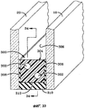
фиг.33 изображает распорный элемент, содержащий две изолирующие полости, проходящие в продольном направлении внутри тела распорного элемента, при этом тело распорного элемента изготовлено из пенопласта и снабжено влагопоглотителем,Fig.33 depicts a spacer element containing two insulating cavities extending in the longitudinal direction inside the body of the spacer element, while the body of the spacer element is made of foam and provided with a desiccant,
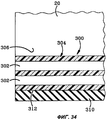
фиг.34 изображает распорный элемент в разрезе по линии 34-34 на фиг.33,Fig.34 shows a spacer element in section along the line 34-34 in Fig.33,
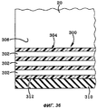
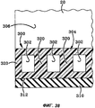
фиг.35 изображает распорный элемент, содержащий шесть изолирующих полостей, проходящих в продольном направлении внутри тела распорного элемента, при этом тело распорного элемента изготовлено из пенопласта и снабжено влагопоглотителем,Fig.35 depicts a spacer element containing six insulating cavities extending in the longitudinal direction inside the body of the spacer element, while the body of the spacer element is made of foam and provided with a desiccant,
фиг.36 изображает распорный элемент в разрезе по линии 36-36 на фиг.35,Fig.36 depicts the spacer element in section along the line 36-36 in Fig.35,
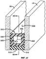
фиг.37 изображает распорный элемент, содержащий отстоящие друг от друга изолирующие полости, проходящие в продольном направлении внутри тела распорного элемента, при этом тело распорного элемента изготовлено из пенопласта и снабжено влагопоглотителем,Fig.37 depicts a spacer element containing spaced apart insulating cavities extending in the longitudinal direction inside the body of the spacer element, while the body of the spacer element is made of foam and provided with a desiccant,
фиг.38 изображает распорный элемент в разрезе по линии 38-38 на фиг.37.Fig.38 depicts a spacer element in section along the line 38-38 in Fig.37.
Аналогичные элементы обозначены одинаковыми позициями по всему тексту описания.Similar elements are denoted by the same positions throughout the description.
Осуществление изобретенияThe implementation of the invention
На фиг.3 и 4 показаны окна 10 и 12 известной конструкции с имитирующими переплеты решетками, разделяющими проходящий свет. Окно 10 представляет пример выполнения, в котором могут использоваться теплоизолирующие стеклопакеты 14 и 16. Стеклопакеты могут быть также встроены в двери зданий или подсобных помещений. Каждый стеклопакет 14 и 16 содержит две стеклянные панели или два стекла 18 и 20, удерживаемые на расстоянии друг от друга распорным элементом, который проходит по периметру и содержит влагопоглотитель.FIGS. 3 and 4
На фиг.5 показана известная имитирующая переплет решетка для разделения света, в которой внутренние разделительные элементы 30, 32 переплета не прикреплены к внутренним поверхностям стекол 18, 20.Figure 5 shows a well-known simulating binding grating for the separation of light, in which the
Все разделительные элементы переплета по изобретению в различных примерах выполнения обозначены общей позицией 100. В различных примерах выполнения элементы переплета имеют различные характеристики, которые будут описаны далее, и общие элементы, обозначенные одними и теми же позициями.All separating elements of the binding according to the invention in various examples of execution are indicated by a
Внутренний разделительный элемент 100 переплета в первом примере выполнения показан на фиг.6. Он предназначен для непосредственного крепления к одному из стекол 18 или 20 с помощью соответствующего клея 101, как это описано в патенте США №5345743, включенном сюда в качестве ссылки. Клей 101 может быть нанесен на тело 102 элемента 100 при его изготовлении. Затем клей 101 закрывают защитным покрытием, которое отделяют перед креплением тела к стеклу 18 или 20. Защитное покрытие позволяет свертывать тело 102 в рулон для хранения и транспортировки. В каждом из примеров выполнения, которые будут описаны ниже, тело 102 предпочтительно изготовлено из гибкого пенопласта любого типа, используемого в данной области для изготовления пенопластовых распорных элементов. Тело 102 может быть снабжено также влагопоглотителем для придания разделительному элементу переплета осушающих свойств.The
Тело 102 имеет два отстоящих друг от друга основания 103, по меньшей мере одно из которых предназначено для крепления к стеклу 18 или 20. В некоторых примерах выполнения тело 102 выполнено с возможностью крепления обоих оснований 103 к стеклам 18 и 20. Тело 102 имеет боковые стенки 105, которые определяют высоту тела 102 и соединяют основания 103.The
Разделительный элемент 100 переплета содержит тело 102, которое образует по меньшей мере одну теплоизолирующую полость 104. Когда разделительные элементы 100 переплета находятся в контакте со стеклами 18 и 20, они действуют как тепловые мосты, передающие энергию через стеклопакет. Обычно полость 104 снижает эффективность теплового моста. Полость 104 проходит продольно и непрерывно внутри тела 102. В примере выполнения по фиг.6 тело 102 образует три теплоизолирующие полости 104. Каждая полость 104 имеет ширину или диаметр, равный или меньше расстояния, отделяющего одну полость 104 от другой. Промежуточные части 106 тела между полостями 104 обеспечивают конструктивную прочность тела 102 и позволяют свертывать его в рулон для хранения и транспортировки.The
Другие конфигурации разделительных элементов 100 переплета представлены на фиг.7А-7Е и 10, 11. Одинаковые части элементов обозначены одними и теми же позициями. В этих примерах полости 104 и промежуточные части 106 тела расположены различным образом, при этом промежуточные части 106 тела предпочтительно имеют ширину, превышающую диаметр или ширину полостей 104. В других примерах выполнения полости 104 могут быть шире частей 106. На фиг.8 и 9 показана в качестве примера экструзионная головка 109 для изготовления тела 102 способом экструзии.Other configurations of the
Тело 102 выполнено с возможностью свертывания в рулон для хранения и транспортировки, при этом оно не сминается. В том случае, когда тело 102 имеет прямоугольное поперечное сечение, более длинная сторона прямоугольника параллельна оси, вокруг которой разделительный элемент 100 свертывают в рулон. Элементы квадратного поперечного сечения могут свертываться в любом направлении, хотя предпочтительно, чтобы лапки 108, описанные далее, выступали с боковой стороны рулона. Для предотвращения смятия тела 102 при свертывании поперечное сечение тела предпочтительно больше поперечного сечения полости 104 или суммарного поперечного сечения полостей 104. В данном случае под площадью поперечного сечения тела подразумевается площадь только сплошных участков сечения, без изолирующих полостей. Соотношение площадей поперечного сечения тела 102 и полости 104 позволяет свертывать тело в рулон без значительного изменения его наружных размеров, так что рулон из разделительного элемента 100 не сминается вбок.The
Тело 102 может также содержать гибкие лапки 108, которые прижимаются к стеклу напротив слоя клея 101. Лапки 108 могут упруго сжиматься, как показано в известном устройстве по патенту США №5345743, так что тело 102 имеет расправленное и сжатое состояние.The
Два дополнительных примера выполнения разделительного элемента 100 переплета показаны на фиг.10 и 11, где теплоизолирующая полость выполнена прямоугольной.Two additional examples of the implementation of the separating
Внутренний разделительный элемент 100 переплета в следующем примере выполнения показан на фиг.12-16. Он выполнен с возможностью перехода между сжатым положением по фиг.15 и расправленным положением по фиг.14, так что может быть прикреплен к обоим стеклам 18 и 20. Стекла 18 и 20 "пульсируют" при изменении давления и температуры. Они "пульсируют" также под действием порывов ветра, сближаясь и отдаляясь друг от друга. В известных решениях разделительных элементов переплета, прикрепленных к обоим стеклам 18 и 20, эти "пульсации" вызывают отслоение элемента от одного или обоих стекол, что портит внешний вид стеклопакета.The
Внутренний разделительный элемент 100 переплета содержит два компенсационных элемента 150, которые позволяют телу 102 регулироваться в соответствии с различными размерами пространства между стеклами 18 и 20 без отслоения оснований 103 от стекол 18 и 20. В примерах выполнения по фиг.12-16 компенсационные элементы 150 выполнены в виде единичного гофра, образованного каждой боковой стенкой 105 тела 102 или частью стенки 105 и одним основанием 103. В примерах выполнения по фиг.12-16 гофр имеет V-образную форму. В контексте данной заявки термин "гофр" относится к V-образной или U-образной форме поперечного сечения боковой стенки 105. В примере по фиг.16 компенсационный элемент 150 выполнен в виде одного гофра, расположенного в каждой стенке 105 между основаниями 103. В примере по фиг.17 компенсационный элемент 150 выполнен в виде U-образного гофра с квадратным внутренним выступом. В примере по фиг.22 два отстоящих друг от друга единичных гофра образованы между частями боковых стенок 105 и каждым основанием 103. В примере по фиг.23 каждый компенсационный элемент 150 представляет собой единичный закругленный гофр U-образной формы. В примере по фиг.25 несколько гофр образуют компенсационный элемент.The
В каждом из описанных примеров выполнения по фиг.12-26 компенсационные элементы 150 обеспечивают автоматическое регулирование высоты тела 102 в соответствии с расстоянием между стеклами 18 и 20 при их сближении или удалении друг от друга.In each of the described embodiments of FIGS. 12-26, the
В примере выполнения по фиг.12-16 тело 102 имеет форму, показанную на фиг.12, и высоту А. Тело 102 может быть изготовлено способом экструзии или формования под давлением. Затем на основания 103 наносят клей 101. Общая высота тела 102 с клеем 101 обозначена А1. Клей может быть нанесен на тело 102 в процессе совместной экструзии. Далее тело 102 со слоями клея 101 укладывают на стекло 18, как показано на фиг.14. Пользователь укладывает разделительные элементы 100 переплета согласно желаемому рисунку переплета. Затем он накладывает стекло 20, как показано на фиг.15, и прижимает его сверху по стрелкам, чтобы прочно прикрепить стекла 18 и 20 к клею 101. Под давлением тело 102 складывается и имеет высоту В в полностью сжатом положении. На фиг.16 показан в разрезе полностью готовый стекпопакет в положении покоя. В этом положении тело 102 имеет высоту промежуточной величины между высотой полностью расправленного и высотой полностью сжатого элемента, так что высота тела 102 может регулироваться в соответствии с движением стекол в любом направлении: друг к другу или друг от друга. Высота тела 102 в положении покоя обозначена С. Высота С больше высоты В, но меньше высоты А1.In the embodiment of FIGS. 12-16, the
В примере выполнения по фиг.12-16 каждый компенсационный элемент 150 выполнен таким образом, что внутренние концы гофр примыкают друг к другу в сжатом положении тела по фиг.15. При этом наружные впадины гофр также закрываются, так что тело 102 может быть свернуто в рулон для хранения в этом сжатом состоянии.In the embodiment of FIGS. 12-16, each
На фиг.17 и 18 показан другой пример выполнения компенсационного элемента 150, в котором внутренняя поверхность каждого гофра также касается внутренней поверхности другого гофра в сжатом положении тела 102, показанном на фиг.17. В этом положении внутренняя полость тела 102 полностью закрыта. На фиг.18 показано полностью расправленное положение компенсационного элемента, в котором боковые стенки 105, по существу, прямые, а поперечное сечение тела 102, по существу, прямоугольное. Каждая боковая стенка 105 выполнена преднамеренно ослабленной в местах ее шарнирного складывания, так что стенки 105 складываются внутрь при переходе тела 102 из расправленного положения по фиг.18 в сжатое положение по фиг.17. Ослабленные участки могут быть выполнены более тонкими по сравнению с остальными участками стенок 105 или они могут иметь прорези для создания ослабленных зон шарнирного складывания. В варианте по фиг.17 и 18 размер В больше размера А.On Fig and 18 shows another example of the implementation of the
В примере выполнения по фиг.19-22 разделительный элемент 100 переплета сходен с элементом переплета по фиг.12-16. Как показано на фиг.22, в положении покоя тело 102 имеет высоту С. На фиг.21 показано положение с полностью сложенными гофрами 150, так что тело 102 имеет высоту В. В полностью расправленном положении, которое не показано, разделительный элемент 100 переплета имеет высоту, по меньшей мере равную А1 (фиг.20). В этом примере выполнения каждый компенсационный элемент 150 образован частью боковой стенки 105 и частью основания 103. Промежуточный участок боковой стенки 105 расположен между противолежащими парами компенсационных элементов. Таким образом, тело 102 имеет четыре компенсационных элемента 150, при этом его конструкция такова, что полость 104 не закрывается полностью, и разделительный элемент 100 переплета сохраняет внутреннюю теплоизолирующую полость в полностью сжатом положении тела 102.In the exemplary embodiment of FIGS. 19-22, the
Следующий пример выполнения элемента 100 переплета с U-образными компенсационными элементами 150 показан на фиг.23 и 24, соответственно в сжатом и расправленном положениях. В сжатом положении стенки 105 складываются внутрь, но не касаются друг друга, так что теплоизолирующая полость 104 остается открытой и выполняет свою функцию. В альтернативных вариантах стенки 105 могут складываться внутрь до контакта друг с другом. При этом полость 104 будет разделяться на две полости. В расправленном положении по фиг.24 компенсационные элементы выпрямляются, и тело 102 имеет, по существу, прямоугольное поперечное сечение.The following exemplary embodiment of a binding
В примере выполнения разделительного элемента 100 переплета по фиг.25 и 26 компенсационные элементы 150 выполнены в виде ряда соединенных концами гофров, которые могут быть U-образными или V-образными. Компенсационные элементы 150 имеют такие размеры, что при их сжатии остается теплоизолирующая полость 104, фиг.25. В этом примере выполнения, как и в других описанных выше, в альтернативном варианте гофры могут иметь такие размеры, чтобы в сжатом положении они примыкали друг к другу с образованием сплошного тела 102. На фиг.26 показано расправленное положение тела 102 с раздвинутыми гофрами.In the exemplary embodiment of the
Альтернативный пример выполнения разделительного элемента 100 переплета показан на фиг.27 и 28. Здесь тело 102 образует щели 152, действующие в качестве компенсационных элементов. Щели 152 проходят внутрь от наружной поверхности каждой боковой стенки. Они позволяют телу 102 расправляться и регулироваться в соответствии с изменениями расстояния между стеклами 18 и 20, как показано на фиг.28. Щели 152 взаимно перекрываются таким образом, что от одного стекла 18 до другого стекла 20 нет прямого пути через тело 102 без пересечения щели 152. В показанном на фиг.27 и 28 примере две щели проходят внутрь от одной боковой стенки 105 и одна щель 152 - от другой боковой стенки. В примере выполнения по фиг.29 и 30 от каждой боковой стенки 105 внутрь проходит одна щель 152.An alternative embodiment of the
Различные примеры выполнения распорного элемента 300 по изобретению представлены на фиг.31-38. Распорные элементы 300 снабжены по меньшей мере одной теплоизолирующей полостью 302, образованной в теле 304 распорного элемента 300. Как показано на чертежах, каждый распорный элемент 300 выполнен с возможностью размещения с небольшим смещением внутрь от наружных кромок стекол 18 и 20 для образования канала уплотнения между стеклами 18 и 20 и обращенной наружу поверхностью 312 распорного элемента 300. Распорные элементы 300 образуют теплоизолирующую полость 306 между стеклами 18 и 20. Каждый распорный элемент 300 прикреплен к стеклам 18 и 20 посредством соответствующего клея 308 и герметика 310, расположенного в канале уплотнения. Герметик 310 препятствует проходу воздуха в теплоизолирующую полость 306 или из нее. Таким образом, герметик 310 в комбинации с распорным элементом 300 герметично закрывает полость 306 и обеспечивает теплоизолирующие свойства стеклопакета.Various exemplary embodiments of the
Один из общих недостатков распорных элементов состоит в том, что они образуют прямой тепловой мост между стеклами 18 и 20, допуская передачу тепловой энергии. Существуют различные решения для снижения до минимума нежелательного эффекта теплового моста. Согласно данному изобретению распорные элементы 300 содержат теплоизолирующие полости 302, заполненные воздухом, который имеет одну температуру и одно давление с воздухом в теплоизолирующей полости 306. Полости 302 снижают эффективность теплового моста и придают распорному элементу улучшенные теплоизолирующие свойства.One of the common disadvantages of the spacer elements is that they form a direct thermal bridge between the
В примере выполнения по фиг.31 тело 304 содержит одну центральную теплоизолирующую полость 302, которая проходит непрерывно в продольном направлении в теле 304. В примере выполнения по фиг.32 тело 304 содержит две отстоящие друг от друга теплоизолирующие полости 302, проходящие непрерывно в продольном направлении в теле 304. Полости 302 отделены друг от друга промежуточной частью 314 тела, ширина которой больше диаметра каждой полости 302. В примере выполнения по фиг.33 тело 304 содержит две отстоящие друг от друга теплоизолирующие полости 302, проходящие непрерывно в продольном направлении в теле 304 на различной высоте. В примере выполнения по фиг.35 тело 304 содержит шесть полостей 302, расположенных парами по ширине и по три в ряд по высоте.In the exemplary embodiment of FIG. 31,
На фиг.37 и 38 показан пример выполнения распорного элемента 300, в котором теплоизолирующие полости 302 проходят в теле 304 прерывистым образом. Хотя в этом случае распорный элемент не имеет таких теплоизолирующих свойств, как в описанных выше примерах, он обладает большей прочностью, так как содержит опорные перемычки 320, разнесенные по всей длине тела 304.FIGS. 37 and 38 show an exemplary embodiment of a
Во всех описанных примерах выполнения тело 304 предпочтительно изготовлено из пенопласта, снабженного влагопоглотителем. В каждом из примеров выполнения барьер для влаги или пара может быть нанесен на три обращенные наружу стороны тела 304 для того, чтобы способствовать герметичному уплотнению теплоизолирующей полости 306.In all the described exemplary embodiments, the
В приведенном выше описании некоторые термины использовались в интересах краткости, ясности и лучшего их понимания. Эти термины, как и конкретные примеры выполнения со ссылками на чертежи, не носят ограничивающего характера. При осуществлении изобретения возможны различные изменения и модификации, не выходящие за пределы объема охраны.In the above description, some terms were used in the interest of brevity, clarity, and a better understanding of them. These terms, as well as specific examples of execution with reference to the drawings, are not limiting. In carrying out the invention, various changes and modifications are possible without departing from the scope of protection.
Claims (8)
Applications Claiming Priority (2)
| Application Number | Priority Date | Filing Date | Title |
|---|---|---|---|
| US39359302P | 2002-07-03 | 2002-07-03 | |
| US60/393,593 | 2002-07-03 |
Publications (2)
| Publication Number | Publication Date |
|---|---|
| RU2005101740A RU2005101740A (en) | 2005-09-20 |
| RU2337223C2 true RU2337223C2 (en) | 2008-10-27 |
Family
ID=30115606
Family Applications (1)
| Application Number | Title | Priority Date | Filing Date |
|---|---|---|---|
| RU2005101740A RU2337223C2 (en) | 2002-07-03 | 2003-07-03 | Counterforce and transom separating element for multiple glass |
Country Status (13)
| Country | Link |
|---|---|
| US (3) | US20040076815A1 (en) |
| EP (1) | EP1651839B1 (en) |
| JP (1) | JP4798751B2 (en) |
| KR (1) | KR101073977B1 (en) |
| CN (1) | CN100476158C (en) |
| AU (2) | AU2003281339B2 (en) |
| CA (2) | CA2750871C (en) |
| DK (1) | DK1651839T3 (en) |
| ES (1) | ES2605401T3 (en) |
| HU (1) | HUE030710T2 (en) |
| PT (1) | PT1651839T (en) |
| RU (1) | RU2337223C2 (en) |
| WO (1) | WO2004005783A2 (en) |
Cited By (2)
| Publication number | Priority date | Publication date | Assignee | Title |
|---|---|---|---|---|
| RU191564U1 (en) * | 2019-05-17 | 2019-08-13 | Вячеслав Александрович Даниленко | VOLUME MOSAIC PRODUCT |
| RU2708215C1 (en) * | 2019-07-01 | 2019-12-04 | Андрей Валентинович Никитин | Adaptive insulating glass unit (versions) |
Families Citing this family (34)
| Publication number | Priority date | Publication date | Assignee | Title |
|---|---|---|---|---|
| PT1651839T (en) * | 2002-07-03 | 2016-11-22 | Quanex Ig Systems Inc | Spacer and muntin elements for insulating glazing units |
| US7026571B2 (en) * | 2002-12-31 | 2006-04-11 | Cardinal Ig Company | Glass masking method using lasers |
| US7716885B2 (en) * | 2004-11-03 | 2010-05-18 | Edgetech I.G., Inc. | Muntin clip and method of using the same |
| GB2432617B (en) * | 2005-11-22 | 2010-06-16 | Komfort Office Environments Plc | A gasket |
| US20080163572A1 (en) * | 2006-01-24 | 2008-07-10 | David Eugene Lee | Decorative grid system and method |
| GB0610634D0 (en) * | 2006-05-30 | 2006-07-05 | Dow Corning | Insulating glass unit |
| US20080197576A1 (en) * | 2007-02-15 | 2008-08-21 | Trout John T | Joint Materials and Configurations |
| SE531001C2 (en) * | 2007-04-12 | 2008-11-11 | Bau How As | Method for forming a seal of a gap and a hose portion adapted to be used in such a method |
| WO2009064905A1 (en) | 2007-11-13 | 2009-05-22 | Infinite Edge Technologies, Llc | Sealed unit and spacer |
| US9309714B2 (en) | 2007-11-13 | 2016-04-12 | Guardian Ig, Llc | Rotating spacer applicator for window assembly |
| US8534019B2 (en) | 2008-07-22 | 2013-09-17 | Quanex Ig Systems, Inc. | Glass block with low-e center lite |
| EP2454437B1 (en) | 2009-07-14 | 2017-05-10 | Guardian IG, LLC | Stretched strips for spacer and sealed unit |
| WO2011156722A1 (en) | 2010-06-10 | 2011-12-15 | Infinite Edge Technologies, Llc | Window spacer applicator |
| US9228389B2 (en) | 2010-12-17 | 2016-01-05 | Guardian Ig, Llc | Triple pane window spacer, window assembly and methods for manufacturing same |
| PL2748383T3 (en) | 2011-08-26 | 2016-01-29 | Saint Gobain | Insulating glazing with thermal protection insulating panel |
| DK2802726T3 (en) | 2012-01-13 | 2016-06-27 | Saint Gobain | Spacer for insulating glass. |
| US9689196B2 (en) | 2012-10-22 | 2017-06-27 | Guardian Ig, Llc | Assembly equipment line and method for windows |
| US9260907B2 (en) | 2012-10-22 | 2016-02-16 | Guardian Ig, Llc | Triple pane window spacer having a sunken intermediate pane |
| USD736594S1 (en) | 2012-12-13 | 2015-08-18 | Cardinal Ig Company | Spacer for a multi-pane glazing unit |
| US8789343B2 (en) | 2012-12-13 | 2014-07-29 | Cardinal Ig Company | Glazing unit spacer technology |
| KR20160095129A (en) | 2013-12-12 | 2016-08-10 | 쌩-고벵 글래스 프랑스 | Spacer for insulating glazing units, comprising extruded profiled seal |
| WO2015086457A2 (en) | 2013-12-12 | 2015-06-18 | Saint-Gobain Glass France | Double glazing having improved sealing |
| EP3105399B1 (en) | 2014-02-03 | 2023-07-05 | V-Glass, Inc. | Compliant hermetic seal system for flat glass panel assembly |
| US10344525B2 (en) | 2014-06-27 | 2019-07-09 | Saint-Gobain Glass France | Insulated glazing with spacer, related methods and uses |
| US10301868B2 (en) | 2014-06-27 | 2019-05-28 | Saint-Gobain Glass France | Insulated glazing comprising a spacer, and production method |
| BR112017017652B1 (en) | 2015-03-02 | 2022-10-18 | Saint-Gobain Glass France | SPACE REINFORCED WITH FIBERGLASS FOR INSULATING GLASS UNIT |
| USD773690S1 (en) * | 2015-03-12 | 2016-12-06 | 3M Innovative Properties Company | Pillar for vacuum insulated glass unit |
| USD777345S1 (en) | 2015-05-21 | 2017-01-24 | Saint-Gobain Glass France | Spacer bar |
| US9777531B1 (en) * | 2015-08-28 | 2017-10-03 | Wayne Conklin | Load bearing spacer for skylight installations |
| US10900274B2 (en) * | 2016-09-02 | 2021-01-26 | Pella Corporation | Anti-rattle elements for internal divider of glass assembly |
| US10526836B2 (en) | 2017-01-30 | 2020-01-07 | GS Research LLC | Adhesive-attached window glazing assembly, multi-glazed window assembly and method therefor |
| WO2019158172A1 (en) | 2018-02-14 | 2019-08-22 | Vkr Holding A/S | Compressible pillar for a vacuum insulated glazing unit |
| EP3643869A1 (en) | 2018-10-22 | 2020-04-29 | Technoform Glass Insulation Holding GmbH | Spacer for an insulating glazing unit preventing thermal stress |
| WO2020097463A1 (en) * | 2018-11-09 | 2020-05-14 | The University Of Maryland, College Park | Low-cost high-performance vacuum insulated glass and method of fabrication |
Family Cites Families (71)
| Publication number | Priority date | Publication date | Assignee | Title |
|---|---|---|---|---|
| US2828235A (en) * | 1954-10-12 | 1958-03-25 | California Reinforced Plastics | Glass faced honeycomb panel and method of making same |
| US2848762A (en) * | 1955-03-11 | 1958-08-26 | Gerald D Peterson | Panel mounting structure |
| US3212179A (en) * | 1963-03-18 | 1965-10-19 | Koblensky Joseph Paul | Process for manufacturing a glazing unit |
| US3308593A (en) * | 1965-03-25 | 1967-03-14 | Crossly Window Corp | Panel for inclusion in a unit to be installed in a building opening |
| US3474587A (en) * | 1967-07-14 | 1969-10-28 | Rimar Mfg Inc | Decorative window grilles |
| US3512320A (en) * | 1968-08-01 | 1970-05-19 | Marcelle Ferron | Decorative window structure |
| JPS473165Y1 (en) * | 1969-08-15 | 1972-02-02 | ||
| US3791095A (en) * | 1971-12-09 | 1974-02-12 | Rimar Mfg Inc | Decorative grill joint |
| US3946531A (en) * | 1975-01-27 | 1976-03-30 | Elca Designs Limited | Muntin bar unitary frame |
| US4113905A (en) * | 1977-01-06 | 1978-09-12 | Gerald Kessler | D.i.g. foam spacer |
| US4564540A (en) * | 1982-12-08 | 1986-01-14 | Davies Lawrence W | Pultruded fibreglass spacer for sealed window units |
| SE453108B (en) * | 1984-08-10 | 1988-01-11 | Lars Eriksson | SPACES FOR THE CREATION OF A CLOSED SPACE BETWEEN TWO GLASS SHEETS |
| US4610901A (en) * | 1984-10-25 | 1986-09-09 | Wayne Boren Corporation | Dual glazed insulatable stained glass window and method of making same |
| US4598520A (en) * | 1984-12-07 | 1986-07-08 | Ellstrom Sven H | Window panel |
| US4652472A (en) * | 1985-09-05 | 1987-03-24 | Omniglass Ltd. | Window unit with decorative bars |
| CA1285177C (en) * | 1986-09-22 | 1991-06-25 | Michael Glover | Multiple pane sealed glazing unit |
| US5007217A (en) * | 1986-09-22 | 1991-04-16 | Lauren Manufacturing Company | Multiple pane sealed glazing unit |
| US4845911A (en) * | 1987-10-13 | 1989-07-11 | Di Giorgio Corporation | Muntin framing system |
| US4994309A (en) * | 1987-12-14 | 1991-02-19 | Lauren Manufacturing Company | Insulating multiple layer sealed units and insulating |
| US4783938A (en) * | 1988-02-05 | 1988-11-15 | Sne Enterprises | Window panel assembly |
| US4950344A (en) * | 1988-12-05 | 1990-08-21 | Lauren Manufacturing Company | Method of manufacturing multiple-pane sealed glazing units |
| US5290611A (en) | 1989-06-14 | 1994-03-01 | Taylor Donald M | Insulative spacer/seal system |
| US5156894A (en) * | 1989-08-02 | 1992-10-20 | Southwall Technologies, Inc. | High performance, thermally insulating multipane glazing structure |
| US4989384A (en) * | 1990-01-02 | 1991-02-05 | Rolscreen Company | Insulated window assembly with internal muntin bars |
| JP2570309Y2 (en) * | 1990-02-02 | 1998-05-06 | 日本フクソーガラス 株式会社 | Double glazing |
| CH681102A5 (en) * | 1990-08-10 | 1993-01-15 | Geilinger Ag | |
| US5345743A (en) * | 1990-10-11 | 1994-09-13 | Peela Corporation | Insulated window assembly with internal muntin bars and method of making same |
| US5773135A (en) * | 1991-04-22 | 1998-06-30 | Lafond; Luc | Insulated assembly incorporating a thermoplastic barrier member |
| US6528131B1 (en) * | 1991-04-22 | 2003-03-04 | Luc Lafond | Insulated assembly incorporating a thermoplastic barrier member |
| US5658645A (en) * | 1991-10-25 | 1997-08-19 | Lafond; Luc | Insulation strip and method for single and multiple atmosphere insulating assemblies |
| US5313762A (en) * | 1991-12-26 | 1994-05-24 | Bayomikas Limited | Insulating spacer for creating a thermally insulating bridge |
| US5439716A (en) * | 1992-03-19 | 1995-08-08 | Cardinal Ig Company | Multiple pane insulating glass unit with insulative spacer |
| US5351459A (en) * | 1992-12-10 | 1994-10-04 | Kassl Robert A | Strength and decoration window grid system |
| ATE152499T1 (en) * | 1992-12-10 | 1997-05-15 | Thermix Gmbh Isolationssysteme | SPACER |
| US5424111A (en) * | 1993-01-29 | 1995-06-13 | Farbstein; Malcolm N. | Thermally broken insulating glass spacer with desiccant |
| CN2163856Y (en) * | 1993-06-21 | 1994-05-04 | 李国业 | General vacuum insulating glass |
| US5461840A (en) * | 1993-10-13 | 1995-10-31 | Taylor; Donald M. | Cardboard spacer/seal as thermal insulator |
| JPH0960433A (en) * | 1995-08-25 | 1997-03-04 | Nippon Parkerizing Co Ltd | Thin double glazing |
| US5962090A (en) * | 1995-09-12 | 1999-10-05 | Saint-Gobain Vitrage Suisse Ag | Spacer for an insulating glazing assembly |
| US5782753A (en) * | 1995-10-20 | 1998-07-21 | United States Surgical Corporation | Surgical retractor |
| US5732517A (en) * | 1996-02-23 | 1998-03-31 | Milikovsky; Roman | Window structure |
| DE19625845A1 (en) * | 1996-06-27 | 1998-01-02 | Flachglas Ag | Insulating glass unit |
| US5983593A (en) * | 1996-07-16 | 1999-11-16 | Dow Corning Corporation | Insulating glass units containing intermediate plastic film and method of manufacture |
| US6286288B1 (en) * | 1996-12-05 | 2001-09-11 | Vertical Ventures V-5, Llc | Integrated multipane window unit and sash assembly and method for manufacturing the same |
| JPH10292743A (en) * | 1997-04-11 | 1998-11-04 | Asahi Glass Co Ltd | Spacer for double glazing and double glazing |
| US6351923B1 (en) * | 1997-07-22 | 2002-03-05 | Wallace H. Peterson | Spacer for insulated windows having a lengthened thermal path |
| US20040079047A1 (en) * | 1997-07-22 | 2004-04-29 | Peterson Wallace H. | Spacer for insulated windows having a lengthened thermal path |
| US6035597A (en) * | 1997-09-12 | 2000-03-14 | Bay Mills Limited | Foam-filled decorative muntin bar for windows and the like |
| JP3327458B2 (en) * | 1997-10-06 | 2002-09-24 | セントラル硝子株式会社 | Double-glazed glass with lattice |
| GB9724077D0 (en) * | 1997-11-15 | 1998-01-14 | Dow Corning Sa | Insulating glass units |
| US6289641B1 (en) * | 1998-01-30 | 2001-09-18 | Ppg Industries Ohio, Inc. | Glazing unit having three or more spaced sheets and a single spacer frame and method of making same |
| DE19805348A1 (en) * | 1998-02-11 | 1999-08-12 | Caprano & Brunnhofer | Spacer profile for insulating washer unit |
| DE19807454A1 (en) * | 1998-02-21 | 1999-08-26 | Ensinger | Plastics spacer for insulating glass panels |
| US6266940B1 (en) * | 1998-07-31 | 2001-07-31 | Edgetech I.G., Inc. | Insert for glazing unit |
| US6177156B1 (en) * | 1998-11-17 | 2001-01-23 | Bowmead Holding Inc. | Simulated divided light windows |
| US6434910B1 (en) * | 1999-01-14 | 2002-08-20 | Afg Industries, Inc. | Rubber core spacer with central cord |
| JP3837970B2 (en) * | 1999-07-08 | 2006-10-25 | 松下電器産業株式会社 | Cylindrical can separation and supply device |
| US7743570B2 (en) * | 1999-08-13 | 2010-06-29 | Edgetech I.G., Inc. | Method of fabricating muntin bars for simulated divided lite windows |
| CA2381738C (en) * | 1999-08-13 | 2008-06-17 | Edgetech I.G., Inc. | Method of fabricating muntin bars for simulated divided lite windows |
| US6240685B1 (en) * | 1999-12-13 | 2001-06-05 | Glass Unlimited Of High Point, Inc. | Simulated multi-pane glass panel |
| DE10024525B4 (en) * | 2000-05-18 | 2005-02-17 | Werner Sobek Ingenieure Gmbh & Co. Kg | Bent glass component |
| US6581341B1 (en) * | 2000-10-20 | 2003-06-24 | Truseal Technologies | Continuous flexible spacer assembly having sealant support member |
| USD450392S1 (en) * | 2000-12-22 | 2001-11-13 | Veka, Inc. | Frame |
| USD450393S1 (en) * | 2000-12-22 | 2001-11-13 | Veka, Inc. | Frame |
| USD451206S1 (en) * | 2000-12-22 | 2001-11-27 | Veka, Inc. | Sill |
| USD458690S1 (en) * | 2000-12-22 | 2002-06-11 | Veka, Inc. | T-bar |
| USD450394S1 (en) * | 2000-12-22 | 2001-11-13 | Veka, Inc. | Meeting rail |
| US7743584B2 (en) * | 2001-08-09 | 2010-06-29 | Edgetech I.G., Inc. | Spacer assembly for insulating glazing units and method for fabricating the same |
| USD461908S1 (en) * | 2001-08-15 | 2002-08-20 | Veka, Inc. | Keeper rail |
| PT1651839T (en) * | 2002-07-03 | 2016-11-22 | Quanex Ig Systems Inc | Spacer and muntin elements for insulating glazing units |
| US6989188B2 (en) * | 2003-11-07 | 2006-01-24 | Technoform Caprano Und Brunnhofer Gmbh & Co. Kd | Spacer profiles for double glazings |
-
2003
- 2003-07-03 PT PT37424298T patent/PT1651839T/en unknown
- 2003-07-03 EP EP03742429.8A patent/EP1651839B1/en not_active Expired - Lifetime
- 2003-07-03 RU RU2005101740A patent/RU2337223C2/en not_active IP Right Cessation
- 2003-07-03 KR KR1020047021704A patent/KR101073977B1/en active IP Right Grant
- 2003-07-03 US US10/613,256 patent/US20040076815A1/en not_active Abandoned
- 2003-07-03 DK DK03742429.8T patent/DK1651839T3/en active
- 2003-07-03 ES ES03742429.8T patent/ES2605401T3/en not_active Expired - Lifetime
- 2003-07-03 CA CA 2750871 patent/CA2750871C/en not_active Expired - Lifetime
- 2003-07-03 CA CA 2491609 patent/CA2491609C/en not_active Expired - Lifetime
- 2003-07-03 AU AU2003281339A patent/AU2003281339B2/en not_active Expired
- 2003-07-03 JP JP2004519831A patent/JP4798751B2/en not_active Expired - Fee Related
- 2003-07-03 HU HUE03742429A patent/HUE030710T2/en unknown
- 2003-07-03 WO PCT/US2003/020965 patent/WO2004005783A2/en active Application Filing
- 2003-07-03 CN CNB038208601A patent/CN100476158C/en not_active Expired - Fee Related
-
2004
- 2004-12-30 US US11/027,664 patent/US20050166546A1/en not_active Abandoned
-
2010
- 2010-01-25 AU AU2010200283A patent/AU2010200283B2/en not_active Expired
-
2014
- 2014-03-26 US US14/225,566 patent/US20140356557A1/en not_active Abandoned
Cited By (2)
| Publication number | Priority date | Publication date | Assignee | Title |
|---|---|---|---|---|
| RU191564U1 (en) * | 2019-05-17 | 2019-08-13 | Вячеслав Александрович Даниленко | VOLUME MOSAIC PRODUCT |
| RU2708215C1 (en) * | 2019-07-01 | 2019-12-04 | Андрей Валентинович Никитин | Adaptive insulating glass unit (versions) |
Also Published As
| Publication number | Publication date |
|---|---|
| KR101073977B1 (en) | 2011-10-17 |
| EP1651839A4 (en) | 2011-04-06 |
| CA2491609A1 (en) | 2004-01-15 |
| CA2750871A1 (en) | 2004-01-15 |
| US20050166546A1 (en) | 2005-08-04 |
| CA2491609C (en) | 2011-11-29 |
| CN1678810A (en) | 2005-10-05 |
| CA2750871C (en) | 2013-05-28 |
| EP1651839A2 (en) | 2006-05-03 |
| AU2003281339A1 (en) | 2004-01-23 |
| DK1651839T3 (en) | 2017-01-02 |
| PT1651839T (en) | 2016-11-22 |
| JP2005532492A (en) | 2005-10-27 |
| EP1651839B1 (en) | 2016-08-31 |
| KR20050024454A (en) | 2005-03-10 |
| AU2010200283A1 (en) | 2010-02-18 |
| WO2004005783A2 (en) | 2004-01-15 |
| HUE030710T2 (en) | 2017-06-28 |
| JP4798751B2 (en) | 2011-10-19 |
| AU2010200283B2 (en) | 2012-11-15 |
| CN100476158C (en) | 2009-04-08 |
| US20140356557A1 (en) | 2014-12-04 |
| AU2003281339B2 (en) | 2009-10-29 |
| US20040076815A1 (en) | 2004-04-22 |
| ES2605401T3 (en) | 2017-03-14 |
| RU2005101740A (en) | 2005-09-20 |
| WO2004005783A3 (en) | 2004-09-02 |
Similar Documents
| Publication | Publication Date | Title |
|---|---|---|
| RU2337223C2 (en) | Counterforce and transom separating element for multiple glass | |
| US8281527B2 (en) | Ribbed tube continuous flexible spacer assembly | |
| CA2739647C (en) | Radiant thermal barrier | |
| HU227418B1 (en) | Continous flexible spacer assembly having sealant support member | |
| EP1144771B1 (en) | Rubber core spacer with central cord | |
| MXPA97006462A (en) | Spacer frame for insulating unit with reinforced side walls to resist the torsio alabeo | |
| WO2004039585A1 (en) | Cellular structure and a method for making a cellular structure | |
| US6740389B2 (en) | Cellular structure with internal limiting member and method for making the cellular structure | |
| US7874114B2 (en) | Radiant heat barrier | |
| EP3688241B1 (en) | A wall element | |
| JP2587003B2 (en) | Heat insulation space forming member and building exterior structure using the same | |
| JP2660958B2 (en) | Building exterior material and building exterior structure using the same | |
| JP2660959B2 (en) | Building exterior material and building exterior structure using the same | |
| CA2181112A1 (en) | Cellular Shade |
Legal Events
| Date | Code | Title | Description |
|---|---|---|---|
| MM4A | The patent is invalid due to non-payment of fees |
Effective date: 20200704 |