RU2336503C2 - Method of preventing formation of crust on tuyere entering into metallurgical capacity and device for implementation of such method - Google Patents
Method of preventing formation of crust on tuyere entering into metallurgical capacity and device for implementation of such method Download PDFInfo
- Publication number
- RU2336503C2 RU2336503C2 RU2005122651/28A RU2005122651A RU2336503C2 RU 2336503 C2 RU2336503 C2 RU 2336503C2 RU 2005122651/28 A RU2005122651/28 A RU 2005122651/28A RU 2005122651 A RU2005122651 A RU 2005122651A RU 2336503 C2 RU2336503 C2 RU 2336503C2
- Authority
- RU
- Russia
- Prior art keywords
- pyrometer
- lance
- passing
- oxygen
- metallurgical
- Prior art date
Links
Images
Classifications
-
- G—PHYSICS
- G01—MEASURING; TESTING
- G01J—MEASUREMENT OF INTENSITY, VELOCITY, SPECTRAL CONTENT, POLARISATION, PHASE OR PULSE CHARACTERISTICS OF INFRARED, VISIBLE OR ULTRAVIOLET LIGHT; COLORIMETRY; RADIATION PYROMETRY
- G01J5/00—Radiation pyrometry, e.g. infrared or optical thermometry
- G01J5/02—Constructional details
- G01J5/04—Casings
-
- C—CHEMISTRY; METALLURGY
- C21—METALLURGY OF IRON
- C21C—PROCESSING OF PIG-IRON, e.g. REFINING, MANUFACTURE OF WROUGHT-IRON OR STEEL; TREATMENT IN MOLTEN STATE OF FERROUS ALLOYS
- C21C5/00—Manufacture of carbon-steel, e.g. plain mild steel, medium carbon steel or cast steel or stainless steel
- C21C5/28—Manufacture of steel in the converter
- C21C5/42—Constructional features of converters
- C21C5/46—Details or accessories
- C21C5/4673—Measuring and sampling devices
-
- C—CHEMISTRY; METALLURGY
- C21—METALLURGY OF IRON
- C21C—PROCESSING OF PIG-IRON, e.g. REFINING, MANUFACTURE OF WROUGHT-IRON OR STEEL; TREATMENT IN MOLTEN STATE OF FERROUS ALLOYS
- C21C5/00—Manufacture of carbon-steel, e.g. plain mild steel, medium carbon steel or cast steel or stainless steel
- C21C5/28—Manufacture of steel in the converter
- C21C5/42—Constructional features of converters
- C21C5/46—Details or accessories
- C21C5/48—Bottoms or tuyéres of converters
-
- F—MECHANICAL ENGINEERING; LIGHTING; HEATING; WEAPONS; BLASTING
- F27—FURNACES; KILNS; OVENS; RETORTS
- F27D—DETAILS OR ACCESSORIES OF FURNACES, KILNS, OVENS OR RETORTS, IN SO FAR AS THEY ARE OF KINDS OCCURRING IN MORE THAN ONE KIND OF FURNACE
- F27D19/00—Arrangements of controlling devices
-
- F—MECHANICAL ENGINEERING; LIGHTING; HEATING; WEAPONS; BLASTING
- F27—FURNACES; KILNS; OVENS; RETORTS
- F27D—DETAILS OR ACCESSORIES OF FURNACES, KILNS, OVENS OR RETORTS, IN SO FAR AS THEY ARE OF KINDS OCCURRING IN MORE THAN ONE KIND OF FURNACE
- F27D21/00—Arrangement of monitoring devices; Arrangement of safety devices
- F27D21/02—Observation or illuminating devices
-
- G—PHYSICS
- G01—MEASURING; TESTING
- G01J—MEASUREMENT OF INTENSITY, VELOCITY, SPECTRAL CONTENT, POLARISATION, PHASE OR PULSE CHARACTERISTICS OF INFRARED, VISIBLE OR ULTRAVIOLET LIGHT; COLORIMETRY; RADIATION PYROMETRY
- G01J5/00—Radiation pyrometry, e.g. infrared or optical thermometry
- G01J5/0037—Radiation pyrometry, e.g. infrared or optical thermometry for sensing the heat emitted by liquids
- G01J5/004—Radiation pyrometry, e.g. infrared or optical thermometry for sensing the heat emitted by liquids by molten metals
-
- G—PHYSICS
- G01—MEASURING; TESTING
- G01J—MEASUREMENT OF INTENSITY, VELOCITY, SPECTRAL CONTENT, POLARISATION, PHASE OR PULSE CHARACTERISTICS OF INFRARED, VISIBLE OR ULTRAVIOLET LIGHT; COLORIMETRY; RADIATION PYROMETRY
- G01J5/00—Radiation pyrometry, e.g. infrared or optical thermometry
- G01J5/02—Constructional details
- G01J5/05—Means for preventing contamination of the components of the optical system; Means for preventing obstruction of the radiation path
- G01J5/051—Means for preventing contamination of the components of the optical system; Means for preventing obstruction of the radiation path using a gas purge
-
- G—PHYSICS
- G01—MEASURING; TESTING
- G01J—MEASUREMENT OF INTENSITY, VELOCITY, SPECTRAL CONTENT, POLARISATION, PHASE OR PULSE CHARACTERISTICS OF INFRARED, VISIBLE OR ULTRAVIOLET LIGHT; COLORIMETRY; RADIATION PYROMETRY
- G01J5/00—Radiation pyrometry, e.g. infrared or optical thermometry
- G01J5/02—Constructional details
- G01J5/07—Arrangements for adjusting the solid angle of collected radiation, e.g. adjusting or orienting field of view, tracking position or encoding angular position
-
- G—PHYSICS
- G01—MEASURING; TESTING
- G01J—MEASUREMENT OF INTENSITY, VELOCITY, SPECTRAL CONTENT, POLARISATION, PHASE OR PULSE CHARACTERISTICS OF INFRARED, VISIBLE OR ULTRAVIOLET LIGHT; COLORIMETRY; RADIATION PYROMETRY
- G01J5/00—Radiation pyrometry, e.g. infrared or optical thermometry
- G01J5/02—Constructional details
- G01J5/08—Optical arrangements
- G01J5/0806—Focusing or collimating elements, e.g. lenses or concave mirrors
-
- G—PHYSICS
- G01—MEASURING; TESTING
- G01J—MEASUREMENT OF INTENSITY, VELOCITY, SPECTRAL CONTENT, POLARISATION, PHASE OR PULSE CHARACTERISTICS OF INFRARED, VISIBLE OR ULTRAVIOLET LIGHT; COLORIMETRY; RADIATION PYROMETRY
- G01J5/00—Radiation pyrometry, e.g. infrared or optical thermometry
- G01J5/02—Constructional details
- G01J5/08—Optical arrangements
- G01J5/0813—Planar mirrors; Parallel phase plates
-
- G—PHYSICS
- G01—MEASURING; TESTING
- G01J—MEASUREMENT OF INTENSITY, VELOCITY, SPECTRAL CONTENT, POLARISATION, PHASE OR PULSE CHARACTERISTICS OF INFRARED, VISIBLE OR ULTRAVIOLET LIGHT; COLORIMETRY; RADIATION PYROMETRY
- G01J5/00—Radiation pyrometry, e.g. infrared or optical thermometry
- G01J5/02—Constructional details
- G01J5/08—Optical arrangements
- G01J5/0818—Waveguides
-
- G—PHYSICS
- G01—MEASURING; TESTING
- G01J—MEASUREMENT OF INTENSITY, VELOCITY, SPECTRAL CONTENT, POLARISATION, PHASE OR PULSE CHARACTERISTICS OF INFRARED, VISIBLE OR ULTRAVIOLET LIGHT; COLORIMETRY; RADIATION PYROMETRY
- G01J5/00—Radiation pyrometry, e.g. infrared or optical thermometry
- G01J5/02—Constructional details
- G01J5/08—Optical arrangements
- G01J5/084—Adjustable or slidable
-
- G—PHYSICS
- G01—MEASURING; TESTING
- G01J—MEASUREMENT OF INTENSITY, VELOCITY, SPECTRAL CONTENT, POLARISATION, PHASE OR PULSE CHARACTERISTICS OF INFRARED, VISIBLE OR ULTRAVIOLET LIGHT; COLORIMETRY; RADIATION PYROMETRY
- G01J5/00—Radiation pyrometry, e.g. infrared or optical thermometry
- G01J5/02—Constructional details
- G01J5/08—Optical arrangements
- G01J5/0846—Optical arrangements having multiple detectors for performing different types of detection, e.g. using radiometry and reflectometry channels
-
- G—PHYSICS
- G01—MEASURING; TESTING
- G01J—MEASUREMENT OF INTENSITY, VELOCITY, SPECTRAL CONTENT, POLARISATION, PHASE OR PULSE CHARACTERISTICS OF INFRARED, VISIBLE OR ULTRAVIOLET LIGHT; COLORIMETRY; RADIATION PYROMETRY
- G01J5/00—Radiation pyrometry, e.g. infrared or optical thermometry
- G01J5/02—Constructional details
- G01J5/08—Optical arrangements
- G01J5/0859—Sighting arrangements, e.g. cameras
-
- G—PHYSICS
- G01—MEASURING; TESTING
- G01J—MEASUREMENT OF INTENSITY, VELOCITY, SPECTRAL CONTENT, POLARISATION, PHASE OR PULSE CHARACTERISTICS OF INFRARED, VISIBLE OR ULTRAVIOLET LIGHT; COLORIMETRY; RADIATION PYROMETRY
- G01J5/00—Radiation pyrometry, e.g. infrared or optical thermometry
- G01J5/60—Radiation pyrometry, e.g. infrared or optical thermometry using determination of colour temperature
Landscapes
- Physics & Mathematics (AREA)
- General Physics & Mathematics (AREA)
- Spectroscopy & Molecular Physics (AREA)
- Engineering & Computer Science (AREA)
- Chemical & Material Sciences (AREA)
- Manufacturing & Machinery (AREA)
- Materials Engineering (AREA)
- Metallurgy (AREA)
- Organic Chemistry (AREA)
- General Engineering & Computer Science (AREA)
- Mechanical Engineering (AREA)
- Radiation Pyrometers (AREA)
- Carbon Steel Or Casting Steel Manufacturing (AREA)
- Waste-Gas Treatment And Other Accessory Devices For Furnaces (AREA)
- Furnace Charging Or Discharging (AREA)
- Length Measuring Devices By Optical Means (AREA)
- Investigating, Analyzing Materials By Fluorescence Or Luminescence (AREA)
- Treatment Of Steel In Its Molten State (AREA)
- Heat Treatment Of Articles (AREA)
- Investigating Or Analysing Materials By Optical Means (AREA)
Abstract
Description
Предпосылки изобретенияBACKGROUND OF THE INVENTION
Изобретение относится к способу предотвращения образования настылей на фурме, проходящей в металлургическую емкость, посредством периодического пропускания кислородосодержащего газа через фурму для растворения настылей.The invention relates to a method for preventing the formation of crusts on a lance passing into a metallurgical vessel by periodically passing an oxygen-containing gas through a lance to dissolve the crusts.
Температуру расплавленного металла в контейнере, например металлургической емкости, обычно измеряют посредством пирометра. Обычно радиационный пирометр бесконтактного типа размещают на конце основания сопла, которое является частью фурмы для продувки газом. Фурма находится на дне или на боковой стенке металлургической емкости. Пирометр также может располагаться на одном конце измерительной штанги, введенной в расплав сверху металлургической емкости. Такие конфигурации раскрыты в DE-OS 964991, DE-A-4025909, EP-A-0362577, US-A-3161499, EP-A-0162949, DE-OS-2438142, US-A-4400097 и JP-A-62207814.The temperature of the molten metal in a container, such as a metallurgical vessel, is usually measured using a pyrometer. Typically, a non-contact type radiation pyrometer is placed at the end of the nozzle base, which is part of a gas blowing lance. The lance is located at the bottom or on the side wall of the metallurgical tank. The pyrometer may also be located at one end of the measuring rod inserted into the melt from above the metallurgical vessel. Such configurations are disclosed in DE-OS 964991, DE-A-4025909, EP-A-0362577, US-A-3161499, EP-A-0162949, DE-OS-2438142, US-A-4400097 and JP-A-62207814 .
Обычно химически неактивный газ вдувают через фурму внутрь расплава, чтобы поддерживать ее отверстие свободным. Тем не менее в измерительном канале могут образовываться настыли, поскольку металл застывает на выходе фурмы, в результате чего измерительный канал время от времени зарастает. Застывший металл на выходе фурмы можно растворять, продувая кислород через канал. Таким образом, можно предупредить зарастание фурмы. Однако кислород значительно искажает измеренные значения и ускоряет износ измерительного канала. Поэтому кислород нужно продувать через канал периодически.Typically, a chemically inactive gas is blown through the lance into the melt to keep its opening free. Nevertheless, accretions can form in the measuring channel, since the metal solidifies at the exit of the lance, as a result of which the measuring channel sometimes heals. The frozen metal at the outlet of the lance can be dissolved by blowing oxygen through the channel. In this way, tuyere overgrowth can be prevented. However, oxygen significantly distorts the measured values and accelerates the wear of the measuring channel. Therefore, oxygen must be purged through the channel periodically.
Сущность изобретенияSUMMARY OF THE INVENTION
Задача была решена в способе предотвращения образования настылей на фурме, проходящей в металлургическую емкость, посредством периодического пропускания кислородосодержащего газа через фурму для растворения настылей, в котором предусмотрено, что перед пропусканием кислородосодержащего газа через фурму регистрируют электромагнитное излучение, исходящее от пятна внутри расплава, посредством двухцветового пирометра, сравнивают интенсивности сигналов пирометра с отношением сигналов пирометра и начинают период пропускания кислородосодержащего газа через фурму при условии, что суммарная интенсивность сигналов ниже заранее определенного порогового значения, при этом отношение сигналов остается, по существу, постоянным. Предпочтительно, для определения порогового значения, используют видеокамеру, размещенную совместно с пирометром вдоль одного оптического пути, и устанавливают соотношение интенсивности сигнала пирометра с изображением видеокамеры, принимают решение на основании видеоизображения, достигнуто ли состояние зарастания, и определяют соответствующее значение интенсивности совокупного сигнала пирометра.The problem was solved in a method for preventing the formation of crusts on a lance passing into a metallurgical tank by periodically passing an oxygen-containing gas through a lance to dissolve the crusts, in which it is provided that before passing the oxygen-containing gas through the lance, electromagnetic radiation emanating from a spot inside the melt is recorded by two-color pyrometer, compare the intensities of the signals of the pyrometer with the ratio of the signals of the pyrometer and begin the period of transmission of oxygen containing gas through the lance provided that the total signal intensity is below a predetermined threshold value, while the signal ratio remains essentially constant. Preferably, to determine the threshold value, a video camera is used, placed together with the pyrometer along one optical path, and the ratio of the signal strength of the pyrometer to the image of the video camera is established, a decision is made based on the video image if the overgrowing state is reached, and the corresponding intensity value of the total pyrometer signal is determined.
Другая задача была решена путем обеспечения устройства, включающего в себя: (а) двухцветовой пирометр, (b) видеокамеру с автофокусировкой, которая выровнена с двухцветовым пирометром вдоль оптического пути, (с) средство изменения ориентации оптического пути и (d) в необязательном порядке дополнительный детектор для измерения электромагнитного излучения, выходящего из металлургической емкости.Another problem was solved by providing a device including: (a) a two-color pyrometer, (b) an autofocus video camera that is aligned with a two-color pyrometer along the optical path, (c) means for changing the orientation of the optical path, and (d) optionally additional a detector for measuring electromagnetic radiation emerging from a metallurgical vessel.
Предпочтительно, устройство дополнительно включает в себя лазерное устройство, пригодное для создания плазмы внутри металлургической емкости, причем дополнительный детектор представляет собой спектрометр, способный регистрировать электромагнитное излучение, исходящее из плазмы. Более предпочтительно, устройство присоединено к внутренней области металлургической емкости посредством трубки, проходящей через фурму.Preferably, the device further includes a laser device suitable for generating plasma inside a metallurgical vessel, the additional detector being a spectrometer capable of detecting electromagnetic radiation emanating from the plasma. More preferably, the device is connected to the inner region of the metallurgical vessel by means of a tube passing through the lance.
В частности заявленное изобретение предлагает способ предотвращения образования настылей на фурме, проходящей в металлургическую емкость, посредством периодического пропускания кислородосодержащего газа через фурму для растворения настылей, в котором для определения начала интервала пропускания кислородосодержащего газа через фурму посредством двухцветового пирометра регистрируют электромагнитное излучение, исходящее от пятна внутри расплава, и сравнивают интенсивности сигналов пирометра с отношением сигналов пирометра и начинают интервал пропускания кислородосодержащего газа через фурму при условии, что суммарная интенсивность сигналов ниже заранее определенного порогового значения, при этом отношение сигналов остается, по существу, постоянным.In particular, the claimed invention provides a method for preventing the formation of crusts on a lance passing into a metallurgical vessel by periodically passing oxygen-containing gas through a lance to dissolve crusts, in which, to determine the beginning of the interval of transmission of oxygen-containing gas through the lance, electromagnetic radiation from a spot inside is recorded by means of a two-color pyrometer melt, and compare the intensities of the signals of the pyrometer with the ratio of the signals of the pyrometer and begin the transmission range of the oxygen-containing gas through the lance is determined provided that the total signal intensity is below a predetermined threshold value, while the signal ratio remains substantially constant.
В одном варианте способа определения порогового значения используют видеокамеру, размещенную совместно с пирометром вдоль одного оптического пути, причем устанавливают соотношение интенсивности сигнала пирометра с изображением видеокамеры, на основании видеоизображения принимают решение, достигнуто ли состояние зарастания, и определяют соответствующее значение интенсивности совокупного сигнала пирометра.In one embodiment of the method for determining the threshold value, a video camera is used, which is placed together with the pyrometer along one optical path, and the ratio of the signal strength of the pyrometer to the image of the video camera is established, based on the video image, a decision is made whether the overgrowing state is reached and the corresponding value of the intensity of the total pyrometer signal is determined.
Предпочтительно видеокамеру применяют для регулировки оптической оси измерительного блока, включающего детектор для сбора видеосигнала и упомянутый двухцветовой пирометр, причем регулировку выполняют на основании видеоизображения, изменяя ориентацию измерительного блока так, чтобы первый конец и второй конец в видеоизображении образовывали концентрические круги.Preferably, the video camera is used to adjust the optical axis of the measuring unit, including a detector for collecting the video signal and said two-color pyrometer, the adjustment being performed on the basis of the video image, changing the orientation of the measuring unit so that the first end and second end in the video image form concentric circles.
Также предпочтительно, если осуществляют измерение длины фурмы, проходящей через металлургическую емкость, первый конец которой обращен внутрь металлургической емкости, а второй конец обращен наружу металлургической емкости, посредством видеокамеры с автофокусировкой, при этом линзовую систему видеокамеры с автофокусировкой регулируют так, чтобы первый конец фурмы, обращенный внутрь металлургической емкости, был в фокусе, и длину фурмы определяют на основании фокусного расстояния и известного положения второго конца фурмы относительно камеры.It is also preferable if the length of the lance passing through the metallurgical vessel is measured, the first end of which is facing inward of the metallurgical vessel and the second end is facing out of the metallurgical vessel by means of an autofocus video camera, wherein the lens system of the autofocus video camera is adjusted so that the first end of the lance facing the metallurgical vessel was in focus, and the length of the lance is determined based on the focal length and the known position of the second end of the lance no camera.
Также предлагается устройство для осуществления способа предотвращения образования настылей на фурме, проходящей в металлургическую емкость, при этом устройство содержит: средство для пропускания кислородосодержащего газа через фурму; измерительный блок, содержащий детектор для сбора видеосигнала с автофокусировкой и двухцветовой пирометр для регистрации через фурму электромагнитного излучения, исходящего от пятна внутри расплава; средство определения начала интервала для пропускания кислородосодержащего газа на основании сравнения интенсивности сигналов пирометра с отношением сигналов пирометра, средство инициирования упомянутого интервала при условии, что суммарная интенсивность сигналов ниже заранее определенного порогового значения и отношение сигналов остается, по существу, постоянным; средство для изменения ориентации измерительного блока и при необходимости дополнительный детектор для измерения электромагнитного излучения, выходящего изнутри металлургической емкости.Also provided is a device for implementing a method for preventing the formation of crusts on a lance passing into a metallurgical vessel, the device comprising: means for passing oxygen-containing gas through the lance; a measuring unit comprising a detector for collecting a video signal with autofocus and a two-color pyrometer for recording electromagnetic radiation emitted from a spot inside the melt through a lance; means for determining the beginning of an interval for passing an oxygen-containing gas based on a comparison of the intensity of the pyrometer signals with the ratio of the pyrometer signals; means for initiating said interval, provided that the total signal intensity is below a predetermined threshold value and the signal ratio remains essentially constant; means for changing the orientation of the measuring unit and, if necessary, an additional detector for measuring electromagnetic radiation emerging from the inside of the metallurgical tank.
Предпочтительно, устройство дополнительно содержит лазерное устройство, пригодное для создания плазмы внутри металлургической емкости, и дополнительный детектор, который является спектрометром, способным регистрировать электромагнитное излучение, исходящее от плазмы.Preferably, the device further comprises a laser device suitable for generating plasma inside a metallurgical vessel, and an additional detector, which is a spectrometer capable of detecting electromagnetic radiation from the plasma.
Целесообразно, если предусмотрено соединение устройства с внутренним пространством металлургической емкости посредством трубки, проходящей через фурму.It is advisable if the device is connected to the inner space of the metallurgical tank by means of a tube passing through the lance.
Подробное описание изобретенияDETAILED DESCRIPTION OF THE INVENTION
На фиг.1 показана предпочтительная конфигурация устройства в соответствии с настоящим изобретением.1 shows a preferred configuration of a device in accordance with the present invention.
Устройство 1 присоединено к контейнеру 2, например, любой металлургической емкости, содержащей расплав, предпочтительно расплавленный металл. Контейнер 2, предпочтительно, является конвертером.The
Фурма для вдувания может быть вставлена в расплав сверху для вдувания в расплав кислорода и, таким образом, превращения железа в сталь. Альтернативно, кислород можно вдувать в конвертер через фурмы на дне и/или в боковых стенках контейнера 2. Устройство 1 присоединено к внутренней стороне контейнера 2 через фурму. Фурма образует измерительный канал А, по которому может распространяться электромагнитное излучение, исходящее из внутренней части контейнера. Один конец фурмы обращен внутрь контейнера. Второй конец измерительного канала 2 обращен к первому измерительному блоку 3, который предпочтительно включает в себя двухцветовой пирометр и видеокамеру.An injection lance can be inserted into the melt from above to inject oxygen into the melt and, thus, convert iron to steel. Alternatively, oxygen can be blown into the converter via tuyeres at the bottom and / or in the side walls of
Предпочтительно, спектрометр 4 и блок 5 лазерной генерации также присоединены к измерительному каналу. Наиболее предпочтительно, устройства 6 обработки данных подключены к измерительному блоку 3.Preferably, the spectrometer 4 and the laser generation unit 5 are also connected to the measurement channel. Most preferably, the data processing devices 6 are connected to the measuring unit 3.
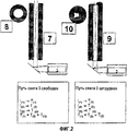
На фиг.2 схематически показаны подробные виды в разрезе и снизу измерительного канала (который на фиг.1 обозначен А). Электромагнитное излучение может беспрепятственно распространяться через свободный измерительный канал 7, что схематически показано на виде 8 снизу. Зарастание, имеющее место вверху измерительного канала, препятствует распространению электромагнитного излучения, что схематически показано в виде 9 снизу. Измерительный блок 3 больше не может регистрировать интенсивность электромагнитного излучения во всей области канала.Figure 2 schematically shows detailed views in section and below the measuring channel (which in figure 1 is indicated by A). Electromagnetic radiation can freely propagate through a
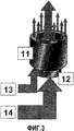
На фиг.3 подробно показано, как может быть сформирован измерительный канал (обозначенный А на фиг.1). Предпочтительно, используется набор из двух концентрических трубок. Измерительный канал, предпочтительно, включает в себя внешнюю трубку 11 и внутреннюю трубку 12, что позволяет вдувать разные газы или газовые смеси в контейнер. Например, газовый поток 13, содержащий азот и/или аргон и метан, можно пропускать через внутреннюю трубку 12, тогда как газовый поток, содержащий азот и/или аргон и кислород, можно пропускать через внешнюю трубку 11. Внутренняя трубка 12 также образует измерительный канал. Поэтому кислород не влияет на измерение.Figure 3 shows in detail how a measuring channel can be formed (indicated by A in figure 1). Preferably, a set of two concentric tubes is used. The measuring channel preferably includes an
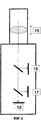
На фиг.4 схематически показан предпочтительный вариант осуществления измерительного блока 3 (фиг.1). Он включает в себя регулируемую линзу 15, два регулируемых зеркала 16, 17 и детектор 18 для сбора видеосигнала. Регулируемая линза 15, предпочтительно, является линзой с автофокусировкой и приводится в действие мотором (не показан).Figure 4 schematically shows a preferred embodiment of the measuring unit 3 (figure 1). It includes an
Процесс определения интервала для пропускания кислородосодержащего газа через фурму начинается с регистрации электромагнитного излучения, исходящего от пятна внутри расплава, посредством двухцветового пирометра и сравнения интенсивности сигналов пирометра с отношением сигналов пирометра. Интервал для пропускания кислородосодержащего газа через фурму инициируется при условии, что суммарная интенсивность сигналов ниже заранее определенного порогового значения и отношение сигналов остается, по существу, постоянным. Пороговое значение нужно заранее определить только один раз визуально на основании изображения видеосигнала. На основании изображения принимается решение, достигнуто ли состояние зарастания, и определяется соответствующая интенсивность совокупного сигнала пирометра. Это пороговое значение затем используется для автоматического инициирования интервала для пропускания кислородосодержащего газа через фурму.The process of determining the interval for passing an oxygen-containing gas through a lance begins with the registration of electromagnetic radiation coming from a spot inside the melt, using a two-color pyrometer and comparing the intensity of the pyrometer signals with the ratio of the pyrometer signals. An interval for passing an oxygen-containing gas through a lance is initiated provided that the total signal intensity is below a predetermined threshold value and the signal ratio remains substantially constant. The threshold value must be determined in advance only once visually based on the image of the video signal. Based on the image, a decision is made whether the overgrowth state is reached, and the corresponding intensity of the total pyrometer signal is determined. This threshold value is then used to automatically initiate an interval for passing oxygen-containing gas through the lance.
Основная идея изобретения заключается в использовании двухцветового пирометра вместо стандартного пирометра. Помимо информации об интенсивности на каждой из двух длин волны, на которых производится измерение, можно вычислять частное двух длин волны.The main idea of the invention is to use a two-color pyrometer instead of a standard pyrometer. In addition to information about the intensity at each of the two wavelengths at which the measurement is performed, the quotient of the two wavelengths can be calculated.
Это обеспечивает дополнительную информацию, которую можно использовать для определения момента времени, когда кислород нужно вдувать через измерительную фурму. Если измеряется интенсивность только на одной длине волны, невозможно решить, вызвано ли изменение интенсивности изменением температуры расплава или формированием настыли на конце фурмы. Благодаря измерению интенсивности на двух длинах волны и сопоставления их друг с другом, например, путем формирования частного двух значений, можно получить информацию о причине такого изменения. Например, если оба значения измеренных интенсивностей падают, но частное этих значений примерно постоянно, можно предполагать, что фурма заросла, тогда как, например, в случае, когда оба значения измеренных интенсивностей падают, но отношение интенсивностей изменяется, можно предположить, что изменяется температура расплава.This provides additional information that can be used to determine the point in time when oxygen needs to be blown through the measuring lance. If the intensity is measured at only one wavelength, it is impossible to decide whether the change in intensity is caused by a change in the temperature of the melt or by the formation of a crust at the end of the lance. By measuring the intensity at two wavelengths and comparing them with each other, for example, by forming a quotient of two values, you can get information about the reason for this change. For example, if both values of the measured intensities fall, but the quotient of these values is approximately constant, we can assume that the lance is overgrown, whereas, for example, in the case when both values of the measured intensities fall, but the ratio of intensities changes, we can assume that the melt temperature changes .
Поэтому преимущество способа, согласно настоящему изобретению, состоит в том, что кислород не нужно без необходимости продувать через измерительный канал только потому, что интенсивность сигнала пирометра падает ниже заранее определенного порогового значения.Therefore, the advantage of the method according to the present invention is that oxygen does not need to be purged unnecessarily through the measuring channel only because the intensity of the pyrometer signal falls below a predetermined threshold value.
Авторами было установлено, что такой вариант осуществления также пригоден для регулировки оптической оси прибора для измерения электромагнитного излучения, например пирометра и спектрометра.The authors found that this embodiment is also suitable for adjusting the optical axis of the device for measuring electromagnetic radiation, such as a pyrometer and spectrometer.
Для регулировки одного или нескольких измерительных устройств, предпочтительно, двухцветового пирометра и/или спектрометра, его/их оптическую/ие ось/и перемещают, пока ближний конец измерительного канала и соответствующее изображение его дальнего конца не будут изображены надлежащим образом согласно геометрии измерительного канала, например, пока правильный трубчатый измерительный канал не даст изображение круга. Эту регулировку предпочтительно производить с помощью видеокамеры. С этой целью видеокамеру и прибор для измерения электромагнитного излучения располагают вдоль одного оптического пути.To adjust one or more measuring devices, preferably a two-color pyrometer and / or spectrometer, its / their optical axis is moved until the near end of the measuring channel and the corresponding image of its far end are properly displayed according to the geometry of the measuring channel, for example until the correct tubular measuring channel gives an image of a circle. This adjustment is preferably performed using a video camera. For this purpose, a video camera and a device for measuring electromagnetic radiation are arranged along one optical path.
Регулировку производят на основании видеоизображения, варьируя ориентацию прибора(ов) и видеокамеры, чтобы первый конец и второй конец в видеоизображении образовывали концентрические круги, это другая задача настоящего изобретения.The adjustment is made based on the video image, varying the orientation of the device (s) and the video camera so that the first end and second end in the video image form concentric circles, this is another objective of the present invention.
Оптимальное положение измерительного(ых) устройства(), то есть двухцветового пирометра и/или спектрометра, достигается, когда геометрии обоих концов измерительного канала представляют собой концентрические изображения, то есть в случае вышеописанного (для примера) трубчатого измерительного канала получаются концентрические круги.The optimal position of the measuring device (s), i.e., a two-color pyrometer and / or spectrometer, is achieved when the geometries of both ends of the measuring channel are concentric images, i.e., in the case of the above-described (for example) tubular measuring channel, concentric circles are obtained.
Для визуализации «ближнего конца» измерительного канала, то есть конца измерительного канала, который обращен к измерительному(ым) устройству(ам) и камере, предпочтительно использовать вспомогательный источник света.To visualize the “near end” of the measuring channel, that is, the end of the measuring channel that faces the measuring device (s) and the camera, it is preferable to use an auxiliary light source.
Неожиданно было обнаружено, что данная конфигурация позволяет также измерять длину фурмы, проходящей через металлургическую емкость 3. Эта информация важна, поскольку она свидетельствует об износе футеровки контейнера. Информация также необходима для фокусировки лазерного пучка.It was unexpectedly found that this configuration also allows you to measure the length of the lance passing through the metallurgical tank 3. This information is important because it indicates the wear of the lining of the container. Information is also needed to focus the laser beam.
С этой целью линзовую систему видеокамеры с автофокусировкой настраивают так, чтобы первый конец фурмы, обращенный внутрь металлургической емкости, был в фокусе. Длину фурмы определяют на основании фокусного расстояния и известного положения второго конца фурмы относительно камеры.For this purpose, the lens system of the autofocus video camera is adjusted so that the first end of the lance, facing the inside of the metallurgical vessel, is in focus. The lance length is determined based on the focal length and the known position of the second end of the lance relative to the camera.
С помощью этой информации лазерный пучок можно сфокусировать таким образом, чтобы интенсивность, достаточная для формирования плазмы, излучение которой можно зарегистрировать спектрометром, присутствовала только на поверхности анализируемого расплава или внутри расплава, но не внутри газовой полости, образованной газом, вдуваемым через измерительный канал.Using this information, the laser beam can be focused so that the intensity sufficient to form a plasma, the radiation of which can be detected by a spectrometer, is present only on the surface of the analyzed melt or inside the melt, but not inside the gas cavity formed by the gas injected through the measuring channel.
Claims (7)
Applications Claiming Priority (2)
| Application Number | Priority Date | Filing Date | Title |
|---|---|---|---|
| DE10259830A DE10259830A1 (en) | 2002-12-19 | 2002-12-19 | Method for keeping a blow nozzle that passes through a metallurgical vessel free of ladle residue |
| DE10259830.4 | 2002-12-19 |
Publications (2)
| Publication Number | Publication Date |
|---|---|
| RU2005122651A RU2005122651A (en) | 2006-01-20 |
| RU2336503C2 true RU2336503C2 (en) | 2008-10-20 |
Family
ID=32404019
Family Applications (1)
| Application Number | Title | Priority Date | Filing Date |
|---|---|---|---|
| RU2005122651/28A RU2336503C2 (en) | 2002-12-19 | 2003-11-05 | Method of preventing formation of crust on tuyere entering into metallurgical capacity and device for implementation of such method |
Country Status (20)
| Country | Link |
|---|---|
| US (1) | US20070132161A1 (en) |
| EP (1) | EP1585950B1 (en) |
| JP (1) | JP2006511702A (en) |
| KR (1) | KR20050092715A (en) |
| CN (1) | CN1729390A (en) |
| AR (1) | AR042324A1 (en) |
| AT (1) | ATE382144T1 (en) |
| AU (1) | AU2003283354A1 (en) |
| BR (1) | BR0317513A (en) |
| CA (1) | CA2510963A1 (en) |
| DE (2) | DE10259830A1 (en) |
| ES (1) | ES2297236T3 (en) |
| IL (1) | IL169194A0 (en) |
| MX (1) | MXPA05006686A (en) |
| NO (1) | NO20053419L (en) |
| PL (1) | PL375984A1 (en) |
| RU (1) | RU2336503C2 (en) |
| TW (1) | TW200420729A (en) |
| WO (1) | WO2004057286A1 (en) |
| ZA (1) | ZA200505414B (en) |
Cited By (1)
| Publication number | Priority date | Publication date | Assignee | Title |
|---|---|---|---|---|
| RU2820634C1 (en) * | 2021-02-10 | 2024-06-06 | ДжФЕ СТИЛ КОРПОРЕЙШН | Electric furnace equipped with video device |
Families Citing this family (4)
| Publication number | Priority date | Publication date | Assignee | Title |
|---|---|---|---|---|
| SE527898C2 (en) | 2004-12-22 | 2006-07-04 | Astrazeneca Ab | Procedure for drug preparation |
| WO2018165937A1 (en) * | 2017-03-16 | 2018-09-20 | 深圳市大疆创新科技有限公司 | Distance-measuring sensor and plant protection unmanned aerial vehicle having distance-measuring sensor |
| US20210146613A1 (en) * | 2017-06-06 | 2021-05-20 | Dmg Mori Advanced Solutions | Systems and Methods for Solidification Rate Control During Additive Manufacturing |
| CN109489823B (en) * | 2018-11-09 | 2020-07-14 | 哈尔滨工业大学 | High temperature measurement device and measurement method of liquid photothermal properties based on sprayed liquid film |
Citations (2)
| Publication number | Priority date | Publication date | Assignee | Title |
|---|---|---|---|---|
| US4400097A (en) * | 1981-02-07 | 1983-08-23 | Ruhrchemie Aktiengesellschaft | System for measuring temperatures in pressurized reactors |
| US4619533A (en) * | 1984-04-24 | 1986-10-28 | Noranda Inc. | Tuyere pyrometer |
Family Cites Families (18)
| Publication number | Priority date | Publication date | Assignee | Title |
|---|---|---|---|---|
| US3161499A (en) * | 1960-10-12 | 1964-12-15 | Percy James Ward | Metallurgical process control |
| FR2238395A5 (en) * | 1973-07-17 | 1975-02-14 | Est Aciers Fins | |
| AR207871A1 (en) * | 1974-08-08 | 1976-11-08 | Maximilianshuette Eisenwerk | REACTIVE GAS INJECTION NOZZLE IN FUSION OR REFINING VESSELS FOR METALS |
| FR2517699A1 (en) * | 1981-12-08 | 1983-06-10 | Lorraine Laminage | METHOD AND DEVICE FOR DETECTING THE CLOGGING OF A BLOW NOZZLE BY THE BOTTOM OF A REFINING CONVERTER |
| JPS60187608A (en) * | 1984-03-06 | 1985-09-25 | Kawasaki Steel Corp | Apparatus for monitoring condition in front of blast furnace tuyere |
| JPH01314928A (en) * | 1988-06-15 | 1989-12-20 | Sumitomo Metal Ind Ltd | Temperature measuring method and apparatus for melting steel |
| DE58908876D1 (en) * | 1988-10-03 | 1995-02-23 | Krupp Ag Hoesch Krupp | Method for the optical coupling of an element analysis system and a laser to liquid metal in a melting vessel. |
| JP3163543B2 (en) * | 1991-03-04 | 2001-05-08 | テキサコ・デベロップメント・コーポレーション | Internal temperature measurement device for processing vessels in severe internal environmental conditions |
| US5315341A (en) * | 1991-12-18 | 1994-05-24 | Eastman Kodak Company | Method and apparatus for through-the-lens distance determination |
| US5283608A (en) * | 1992-02-07 | 1994-02-01 | Samsung Aerospace Industries, Inc. | Camera capable of outputting brightness and measured distance information |
| JP2750995B2 (en) * | 1993-08-19 | 1998-05-18 | 日鉱金属株式会社 | Temperature measuring device for solution in converter |
| FR2710740B1 (en) * | 1993-09-29 | 1995-11-17 | Lorraine Laminage | Method for measuring the evolution of the length of a nozzle for the introduction of a fluid into a liquid metal contained in a metallurgical container, and device for its implementation. |
| US5830407A (en) * | 1996-10-17 | 1998-11-03 | Kvaerner U.S. Inc. | Pressurized port for viewing and measuring properties of a molten metal bath |
| US5963311A (en) * | 1997-09-12 | 1999-10-05 | Stratonics, Inc. | Surface and particle imaging pyrometer and method of use |
| EP0973950A1 (en) * | 1997-12-20 | 2000-01-26 | POHANG IRON & STEEL CO., LTD. | Apparatus for manufacturing molten pig iron and reduced iron by utilizing fluidized bed, and method therefor |
| JPH11326061A (en) * | 1998-05-20 | 1999-11-26 | Sumitomo Metal Ind Ltd | Method and apparatus for measuring temperature of molten metal in furnace |
| EP1134295A1 (en) * | 2000-03-17 | 2001-09-19 | Voest Alpine Industries, Inc. | Submergible probe for viewing and analyzing properties of a molten metal bath |
| LU90610B1 (en) * | 2000-07-10 | 2002-01-11 | Wurth Paul Sa | Optical system for monitoring operating conditions in the tuyere zone of a blast furnace |
-
2002
- 2002-12-19 DE DE10259830A patent/DE10259830A1/en not_active Withdrawn
-
2003
- 2003-11-05 KR KR1020057011220A patent/KR20050092715A/en not_active Ceased
- 2003-11-05 RU RU2005122651/28A patent/RU2336503C2/en not_active IP Right Cessation
- 2003-11-05 AU AU2003283354A patent/AU2003283354A1/en not_active Abandoned
- 2003-11-05 ES ES03775298T patent/ES2297236T3/en not_active Expired - Lifetime
- 2003-11-05 MX MXPA05006686A patent/MXPA05006686A/en unknown
- 2003-11-05 AT AT03775298T patent/ATE382144T1/en active
- 2003-11-05 CN CNA2003801067691A patent/CN1729390A/en active Pending
- 2003-11-05 US US10/576,735 patent/US20070132161A1/en not_active Abandoned
- 2003-11-05 WO PCT/EP2003/012349 patent/WO2004057286A1/en not_active Ceased
- 2003-11-05 JP JP2004561155A patent/JP2006511702A/en active Pending
- 2003-11-05 PL PL03375984A patent/PL375984A1/en unknown
- 2003-11-05 EP EP03775298A patent/EP1585950B1/en not_active Expired - Lifetime
- 2003-11-05 CA CA002510963A patent/CA2510963A1/en not_active Abandoned
- 2003-11-05 DE DE60318333T patent/DE60318333T2/en not_active Expired - Lifetime
- 2003-11-05 BR BR0317513-8A patent/BR0317513A/en not_active IP Right Cessation
- 2003-11-06 TW TW092131091A patent/TW200420729A/en unknown
- 2003-12-05 AR ARP030104505A patent/AR042324A1/en unknown
-
2005
- 2005-06-15 IL IL169194A patent/IL169194A0/en unknown
- 2005-07-05 ZA ZA200505414A patent/ZA200505414B/en unknown
- 2005-07-14 NO NO20053419A patent/NO20053419L/en unknown
Patent Citations (2)
| Publication number | Priority date | Publication date | Assignee | Title |
|---|---|---|---|---|
| US4400097A (en) * | 1981-02-07 | 1983-08-23 | Ruhrchemie Aktiengesellschaft | System for measuring temperatures in pressurized reactors |
| US4619533A (en) * | 1984-04-24 | 1986-10-28 | Noranda Inc. | Tuyere pyrometer |
Cited By (1)
| Publication number | Priority date | Publication date | Assignee | Title |
|---|---|---|---|---|
| RU2820634C1 (en) * | 2021-02-10 | 2024-06-06 | ДжФЕ СТИЛ КОРПОРЕЙШН | Electric furnace equipped with video device |
Also Published As
| Publication number | Publication date |
|---|---|
| ZA200505414B (en) | 2006-04-26 |
| ES2297236T3 (en) | 2008-05-01 |
| IL169194A0 (en) | 2009-02-11 |
| WO2004057286A1 (en) | 2004-07-08 |
| NO20053419L (en) | 2005-09-06 |
| EP1585950A1 (en) | 2005-10-19 |
| US20070132161A1 (en) | 2007-06-14 |
| ATE382144T1 (en) | 2008-01-15 |
| RU2005122651A (en) | 2006-01-20 |
| PL375984A1 (en) | 2005-12-12 |
| CN1729390A (en) | 2006-02-01 |
| DE10259830A1 (en) | 2004-07-01 |
| DE60318333T2 (en) | 2008-06-26 |
| AR042324A1 (en) | 2005-06-15 |
| DE60318333D1 (en) | 2008-02-07 |
| EP1585950B1 (en) | 2007-12-26 |
| CA2510963A1 (en) | 2004-07-08 |
| AU2003283354A1 (en) | 2004-07-14 |
| JP2006511702A (en) | 2006-04-06 |
| KR20050092715A (en) | 2005-09-22 |
| NO20053419D0 (en) | 2005-07-14 |
| BR0317513A (en) | 2005-11-16 |
| MXPA05006686A (en) | 2006-02-22 |
| TW200420729A (en) | 2004-10-16 |
Similar Documents
| Publication | Publication Date | Title |
|---|---|---|
| US6172367B1 (en) | Method and device for measuring electromagnetic waves emanating from a melt | |
| TW562866B (en) | Temperature measuring apparatus and method for molten metal | |
| US10060725B2 (en) | Scanning laser range finder with surface temperature measurement using two-color pyrometry | |
| RU2336503C2 (en) | Method of preventing formation of crust on tuyere entering into metallurgical capacity and device for implementation of such method | |
| CA1250356A (en) | Method and apparatus for measuring slag-forming conditions within converter | |
| US5830407A (en) | Pressurized port for viewing and measuring properties of a molten metal bath | |
| ZA200302380B (en) | Device used for the chemical analysis of material samples and corresponding metallurgical vessel. | |
| JP3266858B2 (en) | Slag detection method, slag detection device, and continuous casting facility | |
| JP2006126062A (en) | Method and apparatus for measuring temperature of molten metal | |
| JPS58196406A (en) | Device for measuring furnace wall profile | |
| US20090262780A1 (en) | Device for Measuring and Analyzing Melt in Metallurgical Vessels | |
| KR102500640B1 (en) | Furnace control method | |
| JP4954688B2 (en) | Coke oven carbonization chamber furnace wall displacement measurement system, and coke oven carbonization chamber furnace wall displacement measurement method | |
| JP4439991B2 (en) | Hot spot radiation measuring method and apparatus | |
| JPH0778248B2 (en) | Blast furnace raceway observation device | |
| JP2005315779A (en) | Hot spot radiation measuring method and apparatus | |
| JP5222812B2 (en) | Hot spot radiation measuring method and apparatus | |
| JP2004037163A (en) | Temperature measuring device for molten metal | |
| WO2024250110A1 (en) | Inspection assembly for a furnace environment | |
| JPH0631683B2 (en) | Position measurement method for molten metal lining surface | |
| JPH06235015A (en) | Sloping prediction method and device for refining vessel | |
| JPS59166612A (en) | Detection of abnormal reaction in converter |
Legal Events
| Date | Code | Title | Description |
|---|---|---|---|
| MM4A | The patent is invalid due to non-payment of fees |
Effective date: 20101106 |