RU2322541C2 - Method of production of endless tape impregnated with gum and tape for paper-making machines and similar industrial applications - Google Patents
Method of production of endless tape impregnated with gum and tape for paper-making machines and similar industrial applications Download PDFInfo
- Publication number
- RU2322541C2 RU2322541C2 RU2005124305A RU2005124305A RU2322541C2 RU 2322541 C2 RU2322541 C2 RU 2322541C2 RU 2005124305 A RU2005124305 A RU 2005124305A RU 2005124305 A RU2005124305 A RU 2005124305A RU 2322541 C2 RU2322541 C2 RU 2322541C2
- Authority
- RU
- Russia
- Prior art keywords
- polymer resin
- substrate
- deposited
- tape
- base substrate
- Prior art date
Links
Images

Classifications
-
- B—PERFORMING OPERATIONS; TRANSPORTING
- B29—WORKING OF PLASTICS; WORKING OF SUBSTANCES IN A PLASTIC STATE IN GENERAL
- B29C—SHAPING OR JOINING OF PLASTICS; SHAPING OF MATERIAL IN A PLASTIC STATE, NOT OTHERWISE PROVIDED FOR; AFTER-TREATMENT OF THE SHAPED PRODUCTS, e.g. REPAIRING
- B29C39/00—Shaping by casting, i.e. introducing the moulding material into a mould or between confining surfaces without significant moulding pressure; Apparatus therefor
- B29C39/14—Shaping by casting, i.e. introducing the moulding material into a mould or between confining surfaces without significant moulding pressure; Apparatus therefor for making articles of indefinite length
- B29C39/18—Shaping by casting, i.e. introducing the moulding material into a mould or between confining surfaces without significant moulding pressure; Apparatus therefor for making articles of indefinite length incorporating preformed parts or layers, e.g. casting around inserts or for coating articles
-
- D—TEXTILES; PAPER
- D21—PAPER-MAKING; PRODUCTION OF CELLULOSE
- D21F—PAPER-MAKING MACHINES; METHODS OF PRODUCING PAPER THEREON
- D21F1/00—Wet end of machines for making continuous webs of paper
-
- D—TEXTILES; PAPER
- D21—PAPER-MAKING; PRODUCTION OF CELLULOSE
- D21F—PAPER-MAKING MACHINES; METHODS OF PRODUCING PAPER THEREON
- D21F3/00—Press section of machines for making continuous webs of paper
- D21F3/02—Wet presses
-
- D—TEXTILES; PAPER
- D21—PAPER-MAKING; PRODUCTION OF CELLULOSE
- D21F—PAPER-MAKING MACHINES; METHODS OF PRODUCING PAPER THEREON
- D21F3/00—Press section of machines for making continuous webs of paper
- D21F3/02—Wet presses
- D21F3/0209—Wet presses with extended press nip
- D21F3/0218—Shoe presses
- D21F3/0227—Belts or sleeves therefor
-
- D—TEXTILES; PAPER
- D21—PAPER-MAKING; PRODUCTION OF CELLULOSE
- D21F—PAPER-MAKING MACHINES; METHODS OF PRODUCING PAPER THEREON
- D21F3/00—Press section of machines for making continuous webs of paper
- D21F3/02—Wet presses
- D21F3/029—Wet presses using special water-receiving belts
-
- D—TEXTILES; PAPER
- D21—PAPER-MAKING; PRODUCTION OF CELLULOSE
- D21F—PAPER-MAKING MACHINES; METHODS OF PRODUCING PAPER THEREON
- D21F7/00—Other details of machines for making continuous webs of paper
- D21F7/08—Felts
-
- Y—GENERAL TAGGING OF NEW TECHNOLOGICAL DEVELOPMENTS; GENERAL TAGGING OF CROSS-SECTIONAL TECHNOLOGIES SPANNING OVER SEVERAL SECTIONS OF THE IPC; TECHNICAL SUBJECTS COVERED BY FORMER USPC CROSS-REFERENCE ART COLLECTIONS [XRACs] AND DIGESTS
- Y10—TECHNICAL SUBJECTS COVERED BY FORMER USPC
- Y10S—TECHNICAL SUBJECTS COVERED BY FORMER USPC CROSS-REFERENCE ART COLLECTIONS [XRACs] AND DIGESTS
- Y10S162/00—Paper making and fiber liberation
- Y10S162/901—Impermeable belts for extended nip press
-
- Y—GENERAL TAGGING OF NEW TECHNOLOGICAL DEVELOPMENTS; GENERAL TAGGING OF CROSS-SECTIONAL TECHNOLOGIES SPANNING OVER SEVERAL SECTIONS OF THE IPC; TECHNICAL SUBJECTS COVERED BY FORMER USPC CROSS-REFERENCE ART COLLECTIONS [XRACs] AND DIGESTS
- Y10—TECHNICAL SUBJECTS COVERED BY FORMER USPC
- Y10T—TECHNICAL SUBJECTS COVERED BY FORMER US CLASSIFICATION
- Y10T428/00—Stock material or miscellaneous articles
- Y10T428/24—Structurally defined web or sheet [e.g., overall dimension, etc.]
- Y10T428/24802—Discontinuous or differential coating, impregnation or bond [e.g., artwork, printing, retouched photograph, etc.]
- Y10T428/2481—Discontinuous or differential coating, impregnation or bond [e.g., artwork, printing, retouched photograph, etc.] including layer of mechanically interengaged strands, strand-portions or strand-like strips
-
- Y—GENERAL TAGGING OF NEW TECHNOLOGICAL DEVELOPMENTS; GENERAL TAGGING OF CROSS-SECTIONAL TECHNOLOGIES SPANNING OVER SEVERAL SECTIONS OF THE IPC; TECHNICAL SUBJECTS COVERED BY FORMER USPC CROSS-REFERENCE ART COLLECTIONS [XRACs] AND DIGESTS
- Y10—TECHNICAL SUBJECTS COVERED BY FORMER USPC
- Y10T—TECHNICAL SUBJECTS COVERED BY FORMER US CLASSIFICATION
- Y10T428/00—Stock material or miscellaneous articles
- Y10T428/249921—Web or sheet containing structurally defined element or component
- Y10T428/249953—Composite having voids in a component [e.g., porous, cellular, etc.]
- Y10T428/249955—Void-containing component partially impregnated with adjacent component
- Y10T428/249958—Void-containing component is synthetic resin or natural rubbers
-
- Y—GENERAL TAGGING OF NEW TECHNOLOGICAL DEVELOPMENTS; GENERAL TAGGING OF CROSS-SECTIONAL TECHNOLOGIES SPANNING OVER SEVERAL SECTIONS OF THE IPC; TECHNICAL SUBJECTS COVERED BY FORMER USPC CROSS-REFERENCE ART COLLECTIONS [XRACs] AND DIGESTS
- Y10—TECHNICAL SUBJECTS COVERED BY FORMER USPC
- Y10T—TECHNICAL SUBJECTS COVERED BY FORMER US CLASSIFICATION
- Y10T428/00—Stock material or miscellaneous articles
- Y10T428/249921—Web or sheet containing structurally defined element or component
- Y10T428/249953—Composite having voids in a component [e.g., porous, cellular, etc.]
- Y10T428/249975—Void shape specified [e.g., crushed, flat, round, etc.]
-
- Y—GENERAL TAGGING OF NEW TECHNOLOGICAL DEVELOPMENTS; GENERAL TAGGING OF CROSS-SECTIONAL TECHNOLOGIES SPANNING OVER SEVERAL SECTIONS OF THE IPC; TECHNICAL SUBJECTS COVERED BY FORMER USPC CROSS-REFERENCE ART COLLECTIONS [XRACs] AND DIGESTS
- Y10—TECHNICAL SUBJECTS COVERED BY FORMER USPC
- Y10T—TECHNICAL SUBJECTS COVERED BY FORMER US CLASSIFICATION
- Y10T442/00—Fabric [woven, knitted, or nonwoven textile or cloth, etc.]
- Y10T442/20—Coated or impregnated woven, knit, or nonwoven fabric which is not [a] associated with another preformed layer or fiber layer or, [b] with respect to woven and knit, characterized, respectively, by a particular or differential weave or knit, wherein the coating or impregnation is neither a foamed material nor a free metal or alloy layer
Abstract
Description
Область техники, к которой относится изобретениеFIELD OF THE INVENTION
Настоящее изобретение относится, в частности, к механизмам для удаления воды из полотна материала, а более конкретно - из волокнистого полотна, перерабатываемого в бумажное изделие на бумагоделательной машине. В частности, в настоящем изобретении предложен способ производства структур бесконечных лент, пропитанных смолами, предназначенных для использования на прессе с длинным зажимом башмачного типа, а также для других использований, связанных с производством бумаги и обработкой бумаги.The present invention relates, in particular, to mechanisms for removing water from a web of material, and more specifically, from a fibrous web processed into a paper product on a paper machine. In particular, the present invention provides a method for producing resin impregnated tape structures for use on a shoe-type long press, as well as for other uses related to paper production and paper processing.
Характеристика предшествующего уровня техникиDescription of the Related Art
В процессе бумажного производства осуществляют формирования волокнистого полотна на формующей ткани путем осаждения на ней суспензии волокон в формирующей секции бумагоделательной машины. В этой формирующей секции происходит приток большого количества воды из суспензии, после чего вновь сформированное полотно поступает в прессующую секцию. Прессующая секция включает в себя ряд прессующих зажимов, в которых волокнистое полотно, опертое на прессующей ткани, подвергается воздействию сжимающих сил, предназначенных для удаления из нее воды. В заключение, полотно поступает в сушильную секцию, которая включает в себя нагретые сушильные барабаны, вокруг которых направляется полотно. Нагретые сушильные барабаны уменьшают влагосодержание полотна до желаемого уровня посредством испарения, вследствие чего получается бумажное изделие.In the papermaking process, fibrous webs are formed on the forming fabric by depositing a suspension of fibers on it in the forming section of the paper machine. In this forming section, a large amount of water flows from the suspension, after which the newly formed web enters the pressing section. The pressing section includes a number of pressing clips in which a fibrous web supported on a pressing fabric is subjected to compressive forces for removing water from it. In conclusion, the web enters the drying section, which includes heated drying drums around which the web is guided. Heated drying drums reduce the moisture content of the web to the desired level by evaporation, resulting in a paper product.
Растущие цены на энергоносители сделали все белее и более желательным удаление как можно большего количества воды из полотна до его попадания в сушильную секцию. Сушильные барабаны часто нагреваются изнутри водяным паром, а соответствующие затраты могут оказаться значительными, особенно когда приходится удалять из полотна большое количество воды.Rising energy prices have made it whiter and more desirable to remove as much water as possible from the canvas before it enters the drying section. Drying drums are often heated from the inside with water vapor, and the corresponding costs can be significant, especially when you have to remove a large amount of water from the canvas.
Сушильные секции традиционно включали в себя ряд зажимов, образованных парами соседних цилиндрических прессующих валиков. В последние годы обнаружено, что использование длинных прессующих зажимов имеет преимущество над использованием зажимов, образованных парами соседних прессующих валиков. Чем больше время, в течение которого полотно может подвергаться прессованию в зажиме, тем больше воды можно извлечь в нем и, следовательно, тем меньше воды останется после этого в полотне для удаления посредством испарения в сушильной секции.Drying sections have traditionally included a number of clamps formed by pairs of adjacent cylindrical pressing rollers. In recent years, it has been found that the use of long pressing clamps has an advantage over the use of clamps formed by pairs of adjacent pressing rollers. The longer the time during which the web can be pressed in the clamp, the more water can be extracted in it and, therefore, the less water will then remain in the web for removal by evaporation in the drying section.
Настоящее изобретение относится, в частности, к прессам с длинными зажимами башмачного типа. В этом семействе прессов с длинными зажимами, зажим образован между цилиндрическим прессующим валиком и дугообразным прижимным башмаком. Последний имеет цилиндрическую вогнутую поверхность, радиус кривизны которой близок к радиусу кривизны цилиндрического прессующего валика. Когда валик и башмак оказываются в тесном физическом соседстве друг с другом, образуется зажим, который может быть в пять - десять раз длиннее в продольном направлении машины, чем зажим, образующийся между двумя прижимными валиками. Поскольку длинный зажим может быть в пять - десять раз длиннее в продольном направлении машины, чем в обычном прессе с двумя валиками, так называемое время пребывания в длинном зажиме, в течение которого волокнистое полотно находится под давлением в длинном зажиме, может оказаться соответственно больше, чем оно было бы в прессе с двумя валиками. Результатом является резкая интенсификация обезвоживания волокнистого полотна в длинном зажиме по сравнению с обычными зажимами на бумагоделательных машинах.The present invention relates in particular to shoe presses with long clamps. In this family of presses with long clamps, a clamp is formed between the cylindrical pressing roller and the arcuate clamping shoe. The latter has a cylindrical concave surface, the radius of curvature of which is close to the radius of curvature of the cylindrical pressing roller. When the roller and the shoe are in close physical proximity to each other, a clamp is formed that can be five to ten times longer in the longitudinal direction of the machine than the clamp formed between the two pressure rollers. Since the long clamp can be five to ten times longer in the longitudinal direction of the machine than in a conventional press with two rollers, the so-called residence time in the long clamp, during which the fibrous web is under pressure in the long clamp, can be correspondingly longer than it would be in a press with two rollers. The result is a sharp intensification of dewatering of the fibrous web in a long clamp compared to conventional clamps on paper machines.
Пресс с длинным зажимом башмачного типа требует специальной ленты, такой, как та, которая проиллюстрирована в патенте США №5238537 (Dutt, Abany International Corp.). Эта лента предназначена для защиты прессующей ткани, которая подпирает, переносит и обезвоживает волокнистое полотно, от ускоренного износа, который должен был бы происходить в случае непосредственного скользящего контакта на поверхности неподвижного прижимного башмака. Такой ленте можно придать гладкую непроницаемую поверхность, которая движется или скользит по неподвижному башмаку на смазочной пленке масла. Эта лента движется примерно с той же скоростью, что и прессующая ткань, вследствие чего прессующая ткань подвергается минимальному трению у поверхности ленты.A press with a long shoe-type clamp requires a special tape, such as that illustrated in US Pat. No. 5,238,537 (Dutt, Abany International Corp.). This tape is designed to protect the pressing fabric, which supports, transfers and dehydrates the fibrous web, from the accelerated wear that would have occurred in the event of direct sliding contact on the surface of the fixed clamping shoe. Such a tape can be given a smooth, impermeable surface that moves or slides along a fixed shoe on an oil lubricating film. This tape moves at about the same speed as the pressing fabric, as a result of which the pressing fabric undergoes minimal friction at the surface of the tape.
Ленты того вида, который проиллюстрирован в патенте США №5238537, изготавливают путем пропитки текстильной ткани основы, которая принимает форму бесконечной петли, синтетической полимерной смолой. В предпочтительном варианте, смола образует покрытие некоторой заранее определенной толщины, по меньшей мере, на внутренней поверхности ленты, так что нити, из которых соткана ткань основы, могут быть защищены от непосредственного контакта с дугообразной составной частью прижимного башмака пресса с длинным зажимом. В частности, именно это покрытие должно иметь гладкую непроницаемую поверхность для легкого скольжения по смазанному башмаку и для предотвращения проникновения любого количества смазочного масла в структуру ленты, что могло бы вызывать загрязнение прессующей ткани - или прессующих тканей - и волокнистого полотна. Ткань основы ленты, проиллюстрированной в патенте США №5238537, может быть соткана из мононитевых нитей в структуре одно- или многослойного плетения и может быть соткана так, чтобы быть достаточно открытой, чтобы обеспечить полную пропитку плетения пропиточным материалом. Это исключает возможность формирования любых пустот в готовой ленте. Такие пустоты могут допускать прохождение смазки, используемой между лентой и башмаком, сквозь эту ленту и загрязнение прижимной ткани - или прижимных тканей - и волокнистого полотна. Ткань основы может быть соткана в плоскости, а затем сшита с приданием бесконечной формы, или может быть соткана бесконечной - в трубчатой форме.Tapes of the kind illustrated in US Pat. No. 5,238,537 are made by impregnating a textile base fabric, which takes the form of an endless loop, with a synthetic polymer resin. In a preferred embodiment, the resin forms a coating of a certain predetermined thickness, at least on the inner surface of the tape, so that the threads of which the warp fabric is woven can be protected from direct contact with the arcuate part of the press shoe with a long clip. In particular, it is this coating that should have a smooth, impermeable surface for easy sliding on the greased shoe and to prevent the penetration of any amount of lubricating oil into the structure of the tape, which could cause contamination of the pressing fabric - or pressing fabrics - and the fibrous web. The warp fabric of the tape illustrated in US Pat. No. 5,238,537 may be woven from monofilament yarns in a single or multi-layered weave structure and may be woven so as to be sufficiently open to provide complete impregnation of the weave with an impregnating material. This eliminates the possibility of the formation of any voids in the finished tape. Such voids may allow the lubricant used between the tape and shoe to pass through the tape and contaminate the pressure fabric — or pressure fabrics — and the fibrous web. The warp fabric may be woven in a plane and then sewn into an infinite shape, or it may be woven endless in a tubular shape.
Когда пропиточный материал затвердевает до достижения твердого состояния, он преимущественно сцепляется с тканью основы за счет механической взаимоблокировки, при этом затвердевший пропиточный материал окружает нити ткани основы. Кроме того, возможно и некоторое химическое сцепление или слипание между затвердевшим пропиточным материалом и материалом нитей ткани основы.When the impregnating material hardens to a solid state, it predominantly adheres to the base fabric due to mechanical interlock, while the hardened impregnating material surrounds the threads of the base fabric. In addition, some chemical adhesion or adhesion between the hardened impregnating material and the material of the warp yarns is possible.
Ленты прессов с длинными зажимами, такие, как та, которая проиллюстрирована в патенте США №5238537, в зависимости от габаритных требований прессов с длинными зажимами, на которых эти ленты устанавливают, имеют длины примерно от 10 до 35 футов (приблизительно 3-11 метров), измеренные в продольном направлении вокруг их форм бесконечных лент, и ширины примерно от 6 до 35 футов (приблизительно 2-11 метров), измеренные в направлении поперек этих форм. Изготовление таких лент осложняется требованием, согласно которому ткань основы должна стать бесконечной до ее пропитки синтетической полимерной смолой.Long clamp press tapes, such as that illustrated in US Pat. No. 5,238,537, depending on the dimensional requirements of the long clamp presses on which these tapes are mounted, have lengths of about 10 to 35 feet (about 3-11 meters) measured in the longitudinal direction around their shapes of endless tapes, and widths of about 6 to 35 feet (about 2-11 meters), measured in the direction across these shapes. The manufacture of such tapes is complicated by the requirement that the base fabric must become infinite before it is impregnated with a synthetic polymer resin.
Зачастую желательно снабдить ленту смоляным покрытием некоторой заранее определенной толщины, располагающимся на внешней поверхности ленты, а также на ее внутренней поверхности. За счет нанесения покрытия на обе стороны ленты, ее текстильная ткань основы становится ближе к нейтральной оси ленты, если не оказывается вообще совпадающей с этой осью. В такой ситуации, внутренние напряжения, которые возникают, когда лента изгибается по мере прохождения вокруг валика или аналогичного средства на бумагоделательной машине, вероятно, будут в меньшей степени вызывать отслаивание покрытия с любой стороны ленты.It is often desirable to provide the tape with a resin coating of a certain predetermined thickness located on the outer surface of the tape, as well as on its inner surface. Due to the coating on both sides of the tape, its textile base fabric becomes closer to the neutral axis of the tape, if it does not even coincide with this axis. In such a situation, the internal stresses that occur when the tape bends as it passes around a roller or similar means on a paper machine are less likely to cause peeling of the coating on either side of the tape.
Более того, когда внешняя поверхность ленты имеет смоляное покрытие некоторой заранее определенной толщины, это позволяет формировать канавки, просверленные вглухую отверстия или другие полости на такой поверхности, не раскрывая какую-либо часть текстильной ткани основы. Эти особенности обеспечивают временное хранение воды, выдавленной из полотна в прессующем зазоре, и обычно получаются путем проточки канавок и сверления отверстий на отдельном технологическом этапе, следующем за отверждением смоляного покрытия.Moreover, when the outer surface of the tape has a resin coating of a certain predetermined thickness, this allows the formation of grooves, drilled blind holes or other cavities on such a surface without revealing any part of the base fabric. These features provide temporary storage of water squeezed out of the web in the pressing gap, and are usually obtained by grooving and drilling holes in a separate process step following the curing of the resin coating.
Настоящее изобретение обеспечивает решение этой конкретной проблемы, то есть, необходимости отдельного технологического этапа или отдельных технологических этапов, которая характеризует известные способы производства структур бесконечных лент, пропитанных смолами, имеющих незаполненный объем в форме канавок, просверленных вглухую отверстий и т.п. на внешних поверхностях упомянутых структур. Более того, настоящее изобретение обеспечивает альтернативный способ производства структур бесконечных лент, пропитанных смолами, используемых в других использованиях, связанных с производством бумаги и обработкой бумаги.The present invention provides a solution to this particular problem, that is, the need for a separate process step or separate process steps, which characterizes known methods for producing structures of endless tapes impregnated with resins, having an unfilled volume in the form of grooves, blind holes, and the like. on the outer surfaces of the mentioned structures. Moreover, the present invention provides an alternative method for the production of structures of endless tapes impregnated with resins used in other uses related to paper production and paper processing.
Краткое изложение сущности изобретенияSummary of the invention
Соответственно, в настоящем изобретении предложен способ производства структур бесконечных лент, пропитанных смолами, предназначенных для использования на прессе с длинным зажимом башмачного типа на бумагоделательной машине и для других использований, связанных с производством бумаги и обработкой бумаги. Этот способ включает в себя первый этап создания основы-подложки для ленты. Эта основа-подложка может быть пропитана ранее материалом полимерной смолы, который образует слой на ее внутренней или внешней поверхности.Accordingly, the present invention provides a method for producing resin impregnated tape structures for use on a shoe-type long press on a paper machine and other uses related to paper production and paper processing. This method includes the first step in creating a base substrate for the tape. This base substrate may be previously impregnated with a polymer resin material that forms a layer on its inner or outer surface.
В альтернативном варианте, основа-подложка может быть выполнена непроницаемой путем осаждения материала полимерной смолы на основу-подложку с целью покрытия всей ее поверхности во время осуществления настоящего изобретения.Alternatively, the substrate substrate may be impermeable by depositing the polymer resin material on the substrate substrate to cover its entire surface during the implementation of the present invention.
Затем на основу-подложку осаждают расходуемый материал в виде рисунка, точно определенного заранее, причем этот заранее определенный рисунок должен характеризовать поверхность изготавливаемой ленты. Расходуемый материал образует слой желаемой толщины поверх основы-подложки, обеспечивая, таким образом, технологическую форму. Расходуемый материал осаждают каплями, имеющими средний диаметр 10 мкм (микрон) или более. Для осаждения расходуемого материала на основу-подложку можно использовать, по меньшей мере, одну пьезоэлектрическую форсунку, хотя вместо пьезоэлектрической форсунки можно использовать другие средства осаждения капель указанного размера, которые известны рядовым специалистам в данной области техники или могут быть разработаны в будущем. После этого на основу-подложку осаждают материал функциональной полимерной смолы, чтобы покрыть ее зоны, не покрытые ранее расходуемым материалом, слоем желаемой толщины, то есть, заполнить технологическую форму, ограниченную расходуемым материалом. Затем обеспечивают отверждение или затвердевание материала полимерной смолы с помощью подходящих средств.Then, the consumable is deposited on the base substrate in the form of a pattern precisely defined in advance, and this predetermined pattern should characterize the surface of the manufactured tape. The consumable material forms a layer of the desired thickness over the base substrate, thus providing a technological form. Consumable material is precipitated with droplets having an average diameter of 10 μm (microns) or more. At least one piezoelectric nozzle can be used to deposit the consumable material on the base substrate, although instead of the piezoelectric nozzle, other means for depositing droplets of a specified size that are known to ordinary specialists in the art or may be developed in the future can be used. After that, the material of the functional polymer resin is deposited on the base substrate in order to cover its zones not previously covered with the consumable material with a layer of the desired thickness, that is, fill the technological form limited by the consumable material. The curing or hardening of the polymer resin material is then ensured by suitable means.
В заключение, удаляют расходуемый материал с ленты, только что изготовленной из подложки, покрытой смолой. Как правило, расходуемый материал удаляют посредством нанесения соответствующего растворителя или приложения тепла. Либо перед удалением расходуемого материала, либо после удаления, осажденный материал полимерной смолы можно - по выбору - подвергнуть абразивной обработке для придания ему одинаковой толщины и гладкой, макроскопически монопланарной поверхности, или раскрыть любой расходуемый материал, который мог быть покрыт материалом полимерной смолы, для последующего удаления.In conclusion, consumable material is removed from the tape just made from the resin coated substrate. Typically, consumables are removed by applying an appropriate solvent or applying heat. Either before removal of the consumable material, or after removal, the deposited polymer resin material can optionally be abraded to give it the same thickness and a smooth, macroscopically monoplanar surface, or any consumable material that may have been coated with the polymer resin material may be opened for later removal.
В одном варианте осуществления изобретения, на ленту, только что изготовленную из основы-подложки, наносят второй материал функциональной полимерной смолы, чтобы заполнить области, ранее занятые удаляемым материалом, чтобы сделать ленту непроницаемой, если она уже не является таковой, и снабдить ленту областями поверхности, имеющими разные свойства.In one embodiment of the invention, a second functional polymer resin material is applied to the tape just made from the base substrate to fill the areas previously occupied by the material to be removed, to make the tape impervious, if not already, and to provide the tape with surface areas having different properties.
Теперь будет приведено более подробное описание настоящего изобретения с частыми ссылками на прилагаемые чертежи, на которых:Now will be given a more detailed description of the present invention with frequent references to the accompanying drawings, in which:
Фиг.1 - схематический вид установки, используемой для производства лент в соответствии со способом согласно настоящему изобретению;Figure 1 is a schematic view of an apparatus used to manufacture tapes in accordance with the method of the present invention;
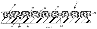
Фиг.2 - поперечное сечение основы-подложки, имеющей слой материала полимерной смолы на своей внутренней поверхности;Figure 2 is a cross section of a base substrate having a layer of polymer resin material on its inner surface;
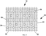
Фиг.3 - вид в плане основы-подложки в том виде, который она должна иметь, выходя со станции формирования и коррекции изображения в установке, показанной на фиг.1;Figure 3 is a plan view of the base substrate in the form that it should have, leaving the image forming and correction station in the apparatus shown in Figure 1;
Фиг.4 - вид в плане основы-подложки в том виде, который она должна иметь, выходя со станции осаждения полимера в установке, показанной на фиг.1;Figure 4 is a plan view of the base substrate in the form that it should have, leaving the deposition station of the polymer in the installation shown in figure 1;
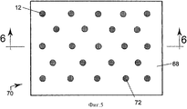
Фиг.5 - вид в плане готовой ленты в том виде, который она должна иметь, выходя со станции удаления элементов технологической формы и станции шлифования установки, показанной на фиг.1;Figure 5 is a plan view of the finished tape in the form that it should have, leaving the station for removing the elements of the technological form and the grinding station of the installation shown in figure 1;
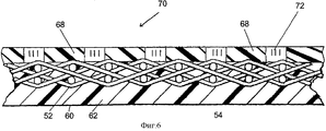
Фиг.6 - поперечное сечение, проведенное так, как показано на фиг.5;6 is a cross-section taken as shown in figure 5;
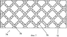
Фиг.7 - вид в плане второго варианта осуществления ленты;7 is a plan view of a second embodiment of a tape;
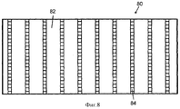
Фиг.8 - вид в плане третьего варианта осуществления ленты;Fig. 8 is a plan view of a third embodiment of a tape;
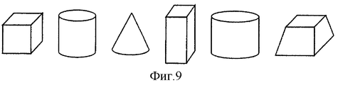
Фиг.9 - перспективное изображение множества характерных форм осажденного материала.9 is a perspective view of a plurality of characteristic forms of deposited material.
Подробное описание предпочтительных вариантов осуществленияDetailed Description of Preferred Embodiments
Способ производства ленты в соответствии с настоящим изобретением начинается с создания структуры основы или основы-подложки. Как правило, основа-подложка представляет собой материал, сотканный из мононитевой пряжи. Вместе с тем, в более широком смысле основа-подложка может быть тканым, нетканым или вязаным материалом, содержащим нити любой из разновидностей, используемых в производстве тканей или лент бумагоделательных машин, используемых для производства нетканых изделий и материалов, и сюда относятся нити из мононитей, наслоенных мононитей, комплексных нитей (мультинитей) и наслоенных комплексных нитей. Эти нити могут быть получены посредством экструзии из любого из материалов полимерных смол, используемых для этой цели специалистами в данной области техники. Соответственно, можно использовать смолы из семейств полиамидных, сложных полиэфирных, полиуретановых, полиарамидных, полиолефиновых и других смол.A method of manufacturing a tape in accordance with the present invention begins with the creation of the structure of the substrate or substrate. Typically, the base substrate is a material woven from monofilament yarn. However, in a broader sense, the base substrate may be a woven, non-woven or knitted material containing yarns of any of the varieties used in the manufacture of fabrics or tapes of paper machines used to produce non-woven products and materials, and this includes monofilament yarns, layered monofilaments, multifilament yarns, and multilayer layered yarns. These filaments can be obtained by extrusion from any of the materials of polymer resins used for this purpose by specialists in this field of technology. Accordingly, resins from the families of polyamide, polyester, polyurethane, polyaramide, polyolefin and other resins can be used.
В альтернативном варианте, основа-подложка может состоять из ячеистых тканей, таких, как те, которые проиллюстрированы в патенте США №4427734 (Johnson). Основа-подложка также может быть спирально-вязаной лентой, принадлежащей к тому семейству, которое проиллюстрировано во многих патентах США, таких, как патент США №4567077 (Gauthier).Alternatively, the base substrate may consist of cellular fabrics, such as those illustrated in US patent No. 4427734 (Johnson). The base substrate may also be a spiral knit tape belonging to the family that is illustrated in many US patents, such as US patent No. 4567077 (Gauthier).
Кроме того, основу-подложку также можно получать путем спирального витья полосы тканого, нетканого, вязаного или ячеистого материала в соответствии со способами, описанными в патенте США №5360656 (Rexfelt и др.). Основа-подложка может соответственно содержать спирально свитую полосу, при этом каждый виток спирали соединен со следующим посредством непрерывного шва, делающего основу-подложку бесконечной в продольном направлении.In addition, the base substrate can also be obtained by spiral winding a strip of woven, non-woven, knitted or cellular material in accordance with the methods described in US patent No. 5360656 (Rexfelt and others). The substrate base may accordingly comprise a spirally twisted strip, wherein each coil of the spiral is connected to the next by means of a continuous seam making the substrate base infinite in the longitudinal direction.
Вышеизложенное не следует считать единственно возможными формами основы-подложки. В качестве альтернативы, можно использовать любые варианты основы-подложки, используемые специалистами в данной области техники в тканях для бумагоделательных машин и соответствующих областях деятельности.The foregoing should not be considered the only possible forms of the substrate substrate. Alternatively, you can use any of the options for the substrate, used by specialists in this field of technology in fabrics for paper machines and related fields of activity.
Сразу же после создания основы-подложки, на одну или обе ее стороны можно нанести один или более слоев войлока из штапельных волокон, делая это способами, хорошо известными обычным специалистам в данной области техники. Возможно, что способом, который лучше всего известен или наиболее распространен, является вшивание, при котором отдельные штапельные волокна в войлоке вводятся в структуру основы совокупностью совершающих возвратно-поступательное движение игл с бородками. В альтернативном варианте, отдельные штапельные волокна можно крепить к основе-подложке посредством гидропереплетения, при котором высоконапорные струи воды выполняют такую же функцию, как вышеупомянутые совершающие возвратно-поступательное движение иглы с бородками. Следует понять, что сразу же после прикрепления войлока из штапельных волокон к основе-подложке любым из этих или других способов, известных специалистам в данной области техники, возможно получение структуры, идентичной структуре прессующей ткани из того семейства, которое обычно используется для обезвоживания влажного бумажного полотна в прессующей секции бумагоделательной машины.Immediately after creating the base substrate, one or more layers of staple fiber felt can be applied to one or both sides of the substrate, using methods well known to those of ordinary skill in the art. It is possible that the method that is best known or most common is stitching, in which individual staple fibers in the felt are introduced into the base structure by a set of reciprocating needles with barbs. Alternatively, individual staple fibers can be attached to the base substrate by means of hydroweaving, in which high-pressure jets of water perform the same function as the aforementioned reciprocating needles with barbs. It should be understood that immediately after attaching the staple fiber felt to the base substrate by any of these or other methods known to those skilled in the art, it is possible to obtain a structure identical to that of the press fabric from the family that is commonly used to dehydrate a wet paper web in the press section of the paper machine.
В качестве еще одной альтернативы отметим, что основа-подложка может быть структурой, которая выполнена непроницаемой для текучих сред, таких, как воздух и вода, и имеет покрытие из материала полимерной смолы, которое, по меньшей мере, частично пропитывает эту структуру и может образовывать слой желаемой толщины на одной или обеих ее сторонах. В частности, это имеет место, когда лента предназначена для использования на прессе с длинным зажимом и требует слоя материала полимерной смолы некоторой заранее определенной толщины на своей внутренней поверхности, чтобы можно было защитить основу-подложку от непосредственного контакта с дугообразной составной частью прижимного башмака пресса с длинным зажимом.As another alternative, we note that the base substrate may be a structure that is impervious to fluids, such as air and water, and has a coating of a polymer resin material that at least partially impregnates this structure and can form a layer of the desired thickness on one or both of its sides. In particular, this occurs when the tape is intended for use on a press with a long clamp and requires a layer of polymer resin material of a certain predetermined thickness on its inner surface so that the substrate substrate can be protected from direct contact with the arcuate constituent part of the press shoe with long clamp.
Ленты, изготавливаемые в соответствии с настоящим изобретением, можно использовать в качестве лент прессов с длинным зажимом, применяемых в прессах с длинным зажимом, и для других приложений, связанных с производством бумаги и обработкой бумаги, например, для каландрирования и переноса листов.Tapes made in accordance with the present invention can be used as tapes of long-press presses used in long-press presses and for other applications related to paper production and paper processing, for example, calendaring and sheet transfer.
Сразу же после создания основы-подложки с добавкой материала войлока из штапельных волокон, ее устанавливают на установке 10, показанной схематически на фиг.1. Следует понять, что основа-подложка может быть либо бесконечной, либо сшиваемой с приданием ей бесконечной формы во время установки на бумагоделательной машине. А если так, то основу-подложку 12, показанную на фиг.1, следует понимать как относительно короткий участок всей длины реальной основы-подложки 12.Immediately after creating the base substrate with the addition of felt material from staple fibers, it is installed on the installation 10, shown schematically in figure 1. It should be understood that the base substrate can be either infinite or stitched to give it an infinite shape during installation on a paper machine. And if so, then the
Когда основа-подложка 12 является бесконечной, наиболее практичной будет ее установка вокруг пары валиков, не показанных на чертеже, но в большинстве случаев знакомых специалистам в области производства тканей для бумагоделательных машин. В такой ситуации, установку 10 можно расположить над одним из двух пролетов основы-подложки 12 между двумя валиками, причем наиболее удобным будет расположение над верхним пролетом. Однако вне зависимости от того, бесконечная она или нет, основе-подложке 12 предпочтительно сообщают подходящую степень натяжения во время процесса. Более того, чтобы предотвратить провисание, основу-подложку, когда она движется через установку 10, можно опереть снизу на горизонтальный опорный элемент.When the
Переходя теперь к более конкретному рассмотрению фиг.1, где основа-подложка 12 показана движущейся в направлении вверх через установку 10 при осуществлении способа согласно настоящему изобретению, отмечаем, что установка 10 содержит цепочку из нескольких станций, через которые в процессе шагового перемещения может проходить основа-подложка 12 по мере выхода из них изготавливаемой ленты.Turning now to a more specific consideration of FIG. 1, where the
Эти станции идентифицируются следующим образом:These stations are identified as follows:
1) станция 14 осаждения элементов технологической формы;1) station 14 deposition of elements of the technological form;
2) станция 24 формирования и коррекции изображения;2) station 24 of the formation and correction of the image;
3) станция 36 осаждения полимера;3) a polymer deposition station 36;
4) станция 48 удаления элементов технологической формы; 4) station 48 removal of technological elements;
5) станция 50 шлифования по выбору.5) optionally grinding station 50.
С соответствии с настоящим изобретением, если подложка уже не сделана непроницаемой для текучих сред, таких, как вода и воздух, сначала может понадобиться снабдить ее покрытием из материала полимерной смолы, который, по меньшей мере, частично пропитывает основу-подложку, чтобы покрыть всю поверхность основы-подложки для придания непроницаемости основе-подложке. Этого можно достичь путем использования станции 36 осаждения полимера установки 10, или с помощью других средств, подходящих для этой цели.In accordance with the present invention, if the substrate is not already impervious to fluids, such as water and air, it may first be necessary to provide it with a coating of a polymer resin material that at least partially impregnates the base substrate to cover the entire surface substrate substrates for impenetration of the substrate substrate. This can be achieved by using the polymer deposition station 36 of the installation 10, or by other means suitable for this purpose.
На станции 36 осаждения полимера, поперечные направляющие 38, 40 служат опорой дозировочному устройству, такому, как матрица 42 мощных форсунок, совершающая поступательное движение вдоль них в направлении, поперечном направлению движения основы-подложки 12 через установку 10, а также между ними в направлении, параллельном направлению движения основы-подложки 12, когда последняя находится в покое. Матрицу 42 мощных форсунок можно использовать на основу-подложку 12 или внутри нее с целью придания непроницаемости и - по выбору - для формирования слоя желаемой толщины на ней. Для осаждения желаемого количества материала, матрица 42 мощных форсунок может совершить один или более проходов над основой-подложкой 12.At the polymer deposition station 36, the transverse guides 38, 40 support the metering device, such as an array of powerful nozzles 42, which translates along them in a direction transverse to the direction of movement of the
Разобравшись с этим предварительным этапом, который выполняют при необходимости, вернемся теперь к первой станции. На первой станции - станции 14 осаждения элементов технологической формы - матрица 16 пьезоэлектрических форсунок, установленная на поперечных направляющих 18, 20 и совершающая поступательное движение вдоль них в направлении, поперечном направлению движения основы-подложки 12 через установку 10, а также между ними в направлении, параллельном направлению движения основы-подложки 12, используется для осаждения в процессе повторяемых этапов, чтобы нанести желаемое количество расходуемого материала на основу-подложку 12 в виде заранее определенного рисунка. В альтернативном варианте, при воплощении настоящего изобретения на практике можно использовать другие средства для осаждения малых капель, необходимых для практического воплощения настоящего изобретения, которые будут рассмотрены ниже и могут быть уже известны обычным специалистам в данной области техники или могут быть разработаны в будущем. Кроме того, осаждение расходуемого материала не обязательно должно происходить поперек движения основы-подложки, а может происходить и параллельно такому движению, может быть спиральным по отношению к такому движению или может осуществляться любым другим образом, подходящим для рассматриваемого назначения.Having dealt with this preliminary stage, which is carried out if necessary, we will now return to the first station. At the first station - station 14 deposition of technological elements - a matrix of 16 piezoelectric nozzles mounted on the transverse guides 18, 20 and performing translational motion along them in the direction transverse to the direction of movement of the
Расходуемый материал может проникать в основу-подложку, если на последнюю не нанесен слой материала функциональной полимерной смолы, покрывающий и делающий ее непроницаемой, и - если это желательно - образует слой желаемой толщины на ней с получением заранее определенного рисунка. Этот рисунок может быть матрицей дискретных площадок, которые, в конце концов, становятся площадками соответствующей матрицы дискретных отверстий, обеспечивающими незаполненный объем на поверхности ленты. В таком случае расходуемый материал, который в дальнейшем удаляют в процессе производства ленты и которого нет в готовой ленте, осаждают в этих дискретных площадках, где он становится сцепленным и может наращиваться до достижения заранее определенной высоты и/или формы над поверхностью основы-подложки 12. В своей совокупности, дискретные площадки, имеющие удаляемый материал, представляют собой технологическую форму, которую впоследствии заполняют функциональным материалом полимерной смолы, называемым так потому, что он является функциональной частью ленты, когда ее изготовление завершено.Consumable material can penetrate the base substrate if the last is not coated with a layer of functional polymer resin material that covers and makes it impermeable, and - if desired - forms a layer of the desired thickness on it to obtain a predetermined pattern. This pattern can be a matrix of discrete pads, which, in the end, become pads of the corresponding matrix of discrete holes, providing an empty space on the surface of the tape. In this case, the consumable material, which is subsequently removed during the production of the tape and which is not present in the finished tape, is deposited in these discrete areas where it becomes entangled and can grow until a predetermined height and / or shape above the surface of the
В альтернативном варианте, удаляемый материал может быть осажден в виде полунепрерывной сетки, например, полунепрерывного рисунка, простирающегося, по существу по всей основе-подложке 12, по существу, линейно, так что удаляемый материал сцепляется с основой-подложкой 12 или с материалом полимерной смолы, нанесенным ранее для придания непроницаемости основе-подложке, вдоль линий, которые в основном параллельны друг другу и равноотстоят друг от друга. Такие линии могут быть либо прямыми, либо кривыми, либо зигзагообразными. В более обобщенном случае, полунепрерывная сетка содержит прямые или кривые линии, или линии, имеющие и прямые, и кривые сегменты, которые отстоят друг от друга и не пересекаются друг с другом. В итоге, полунепрерывная сетка обеспечивает поверхность готовой ленты с совокупностью канавок, которые могут обеспечить незаполненный объем для временного хранения воды, выдавленной из влажного листа бумаги.Alternatively, the material to be removed may be deposited in the form of a semicontinuous mesh, for example, a semicontinuous pattern, extending substantially along the
В еще одном альтернативном варианте, удаляемый материал может быть осажден в виде непрерывной сетки, простирающейся, по существу, на всем протяжении обоих размеров поверхности основы-подложки 12 и ограничивающей совокупность дискретных открытых зон в виде заранее определенной матрицы. Эти дискретные открытые зоны, в конце концов, заполняются материалом полимерной смолы и, в конце концов, становятся площадками дискретных зон, заполненными материалом полимерной смолы, на поверхности ленты. Непрерывная сетка может обеспечить, например, получение поверхности готовой ленты с совокупностью пересекающихся крест-накрест канавок. Отметим, что до сих пор канавки, как правило, выполняли в ленте путем проточки. Соответственно, они были в основном прямыми или, по существу, прямыми в результате операций расточки. Также отметим, что просверленные вглухую отверстия были в основном круглыми - тоже в результате операций сверления или расточки. Настоящее изобретение преимущественно позволяет избежать этих ограничений, и это приводит к тому, что можно создавать пустоты любой желаемой формы благодаря свободе осаждения удаляемого материала в виде любого рисунка, конечной целью которого является создание этих пустот.In yet another alternative embodiment, the material to be removed can be deposited in the form of a continuous grid extending substantially along the entire length of both surface sizes of the
Переходя теперь к рассмотрению чертежей, отмечаем, что матрица 16 пьезоэлектрических форсунок содержит, по меньшей мере, одну, а предпочтительно - совокупность отдельных управляемых компьютером пьезоэлектрических форсунок, каждая из которых функционирует как насос, активным компонентом которого является пьезоэлектрический элемент. На практике можно использовать матрицу, содержащую до 256-ти пьезоэлектрических форсунок или более, если технология позволяет это. Активный компонент представляет собой кристалл или керамический элемент, который физически деформируется за счет прикладываемого электрического сигнала. Эта деформация позволяет кристаллу или керамическому элементу функционировать как насос, который физически выбрасывает каплю жидкого материала каждый раз, когда принимается соответствующий электрический сигнал. Как таковой, способ использования пьезоэлектрических форсунок для повторяющейся подачи капель желаемого материала с целью нанесения желаемого количества материала в желаемой форме в ответ на управляемые компьютером электрические сигналы обычно называют способом "подачи капель по потребности".Turning now to the consideration of the drawings, we note that the matrix 16 of piezoelectric nozzles contains at least one, and preferably a combination of separate computer-controlled piezoelectric nozzles, each of which functions as a pump, the active component of which is a piezoelectric element. In practice, you can use a matrix containing up to 256 piezoelectric nozzles or more, if the technology allows it. The active component is a crystal or ceramic element that is physically deformed due to the applied electrical signal. This deformation allows the crystal or ceramic element to function as a pump that physically ejects a drop of liquid material each time an appropriate electrical signal is received. As such, the method of using piezoelectric nozzles to repeatedly supply droplets of the desired material in order to deposit the desired amount of material in the desired form in response to computer-controlled electrical signals is commonly referred to as the “droplet on demand” method.
Степень точности форсунки при осаждении материала будет зависеть от размеров и формы формируемой структуры. Тип используемой форсунки и вязкость наносимого материала также будут влиять на точность выбранной форсунки.The degree of accuracy of the nozzle during deposition of the material will depend on the size and shape of the formed structure. The type of nozzle used and the viscosity of the applied material will also affect the accuracy of the selected nozzle.
Обращаясь снова к фиг.1, отметим, что матрица 16 пьезоэлектрических форсунок, начиная от края основы-подложки 12 или - что предпочтительно - от опорной нити, проходящей в направлении ее длины, совершает поступательное движение в продольном и поперечном направлениях над основой-подложкой 12, а когда основа-подложка 12 находится в покое - осаждает материал полимерной смолы в виде исключительно маленьких капель, имеющих номинальный диаметр 10 мкм (10 микрон) или более, например, 50 мкм (50 микрон) или 100 мкм (100 микрон), в виде одного из вышеописанных рисунков. Поступательным движением матрицы 16 пьезоэлектрических форсунок в продольном и поперечном направлениях относительно основы-подложки 12 и осаждением капель удаляемого материала из каждой пьезоэлектрической форсунки в матрице 16 контролируемым образом управляет компьютер, вследствие чего получается заранее определенный рисунок расходуемого материала, геометрия которого является управляемой в трех плоскостях - по длине, ширине и глубине или высоте (то есть, по размерам х, у, z или в соответствующих направлениях) на основе-подложке 12. Для осаждения желаемого количества удаляемого материала, матрица 16 пьезоэлектрических форсунок может совершить один или более проходов над основой-подложкой 12. То есть, за счет осаждения капель в виде повторяющегося рисунка, что реализуется путем наслаивания одной капли поверх другой, обеспечивается возможность регулирования высоты или размера в направлении z удаляемого материала на подложке 12 (или предварительно нанесенного материала полимерной смолы), и этот параметр можно сделать везде одинаковым, переменным или регулируемым каким-то иным образом по желанию.Turning again to FIG. 1, we note that the matrix 16 of piezoelectric nozzles, starting from the edge of the
Для осаждения желаемого количества материала и придания ему желаемой формы, матрица 16 пьезоэлектрических форсунок может совершить один или более проходов над основой-подложкой 12. В этой связи отметим, что осадки могут принимать любое количество форм, изображенных в общих чертах на фиг.9. Эти формы могут представлять собой куб, круговой цилиндр или конус, прямоугольный параллелепипед, овальный цилиндр, трапецеидальную призму с более широким основанием внизу и сужением кверху, и т.д. В зависимости от конструкторского выбора, необходимое количество осаждаемого материала можно наслаивать, постепенно уменьшая подачу по мере повторных проходов форсунки над зоной осаждения.To deposit the desired amount of material and give it the desired shape, the matrix 16 of piezoelectric nozzles can make one or more passes over the
Когда рисунок на основе-подложке 12 завершен в полосе между поперечными направляющими 18, 20, эту основу-подложку 12 перемещают в направлении длины на расстояние, величина которого равна ширине полосы, и повторяют вышеописанную процедуру, чтобы получить заранее определенный рисунок в новой полосе, соседней с той, которая завершена ранее. Посредством этого повторения можно снабдить основу-подложку 12 заранее определенным рисунком.When the
В альтернативном варианте, матрицу 16 пьезоэлектрических форсунок - снова начиная от края основы-подложки 12 или - что предпочтительно - от опорной нити, проходящей в направлении ее длины, поддерживают в некотором фиксированном положении относительно поперечных направляющих 18, 20, а основу-подложку 12 перемещают под матрицей для осаждения материала полимерной смолы в виде желаемого рисунка в продольной полосе около основы-подложки 12. После завершения этой продольной полосы, матрицу 16 пьезоэлектрических форсунок перемещают в поперечном направлении по поперечным направляющим 18, 20 на расстояние, величина которого равна ширине продольной полосы, и повторяют вышеописанную процедуру, чтобы получить заранее определенный рисунок в новой полосе, соседней с той, которая завершена ранее. Посредством этого повторения можно снабдить всю основу-подложку 12 заранее определенным рисунком.Alternatively, the matrix 16 of piezoelectric nozzles — again starting from the edge of the
На одном конце поперечных направляющих 18, 20 предусмотрена станция 22 контроля форсунок, предназначенная для тестирования каждого потока материала полимерной смолы из каждой форсунки. В данном случае форсунки можно прочищать и очищать, чтобы автоматически восстанавливать работу любого неправильно функционирующего блока форсунок.At one end of the transverse guides 18, 20, a nozzle control station 22 is provided for testing each flow of polymer resin material from each nozzle. In this case, the nozzles can be cleaned and cleaned to automatically restore the operation of any incorrectly functioning nozzle block.
Удаляемый материал является твердым материалом, который быстро плавится при нагревании и затвердевает, жестко сцепляясь с основой-подложкой 12 при охлаждении. Удаляемый материал можно подавать из нагретого резервуара, где он поддерживается в жидком состоянии, и перекачивать по питающей трубе к пьезоэлектрической форсунке или пьезоэлектрическим форсункам. Вязкость удаляемого материала в точке подачи важна при определении размера и формы капель, образующихся на основе-подложке (или предварительно нанесенном материале полимерной смолы) и заблаговременного определения разрешения рисунка, который, в конечном счете, получается.The material to be removed is a solid material that quickly melts when heated and solidifies, adhering to the
Отметим, что рисунок может быть произвольным, т.е. повторяющимся произвольным рисунком на основе-подложке, или такие рисунки могут повторяться от ленты к ленте для управления качеством.Note that the pattern can be arbitrary, i.e. repeating arbitrary pattern on a substrate basis, or such patterns can be repeated from tape to tape to control quality.
Удаляемый материал может быть безводным удаляемым растворителем парафином или водорастворимым парафином, таким, как водорастворимый полиэтиленгликоль или поливиниловый спирт. Обобщая, можно сказать, что удаляемый материал может быть любым материалом, который можно выпускать через пьезоэлектрическую форсунку исключительно малыми каплями, размеры которых находятся в вышеуказанном диапазоне, и который, в конце концов, можно удалить с основы-подложки 12 с помощью средств, не разрушающих основу-подложку 12 и какой-либо материал полимерной смолы, нанесенный на нее. В дополнение к этим требованиям, удаляемый материал должен быть наделен способностью к как можно более быстрому затвердеванию или отверждению на основе-подложке 12 после осаждения на нее, чтобы можно было управлять его распределением на или в основе-подложке 12.The material to be removed may be an anhydrous solvent to be removed with paraffin or a water-soluble paraffin such as water-soluble polyethylene glycol or polyvinyl alcohol. Summarizing, we can say that the material to be removed can be any material that can be discharged through the piezoelectric nozzle in extremely small droplets, the sizes of which are in the above range, and which, in the end, can be removed from the
На второй станции - станции 24 формирования и коррекции изображения - имеются поперечные направляющие 26, 28, которые служат опорой цифровой камере 30 передачи изображения, выполненной с возможностью поступательного движения по ширине основы-подложки 12, и матрица 32 корректирующих форсунок, выполненная с возможностью поступательного движения, как по ширине основы-подложки 12, так и в продольном направлении относительно нее между поперечными направляющими 26, 28, а сама основа-подложка 12 при этом неподвижна.At the second station — the image forming and correction station 24 — there are transverse guides 26, 28 that support the digital image transfer camera 30, which is capable of translational movement along the width of the
Цифровая камера 30 передачи изображения осуществляет осмотр осажденного удаляемого материала, чтобы локализовать любые дефектные или пропущенные дискретные элементы технологической формы или аналогичные неоднородности в полунепрерывном или непрерывном рисунке, полученном упомянутым образом на основе-подложке 12. Сравнения между реальным и желаемым рисунками проводятся с помощью процессора быстрого распознавания образов (БРО), работающего вместе с цифровой камерой 30 передачи изображения. Процессор БРО выдает в матрицу 32 корректирующих форсунок сигналы осаждения дополнительного материала полимерной смолы на элементы, определенные как дефектные или пропущенные. Аналогично сказанному ранее, на одном конце поперечных направляющих 26, 28 предусмотрена станция 34 контроля корректирующих форсунок, предназначенная для тестирования каждого потока материала полимерной смолы из каждой корректирующей форсунки. В данном случае каждую корректирующую форсунку можно прочищать и очищать, чтобы автоматически восстанавливать работу любого неправильно функционирующего блока корректирующих форсунок.The digital image transfer camera 30 inspects the deposited material being removed to locate any defective or missing discrete technological form elements or similar heterogeneities in the semi-continuous or continuous pattern obtained in the aforementioned manner on the basis of the
На третьей станции - станции 36 осаждения полимера, рассмотренной ранее, поперечные направляющие 38, 40 служат опорой дозировочному устройству, такому, как матрица 42 мощных форсунок, совершающая поступательное движение вдоль них в направлении, поперечном направлению движения основы-подложки 12 через установку 10, а также между ними в направлении, параллельном направлению движения основы-подложки, когда последняя находится в покое. Матрицу 42 мощных форсунок можно использовать для осаждения материала функциональной полимерной смолы на поверхность основы-подложки 12, за исключением областей, имеющих удаляемый материал, с целью заполнения технологической формы, образованной удаляемым материалом на основе-подложке 12, для формирования слоя желаемой толщины на ней. Последний может быть полиуретановой или фоторезистивной смолой, а также другими смолами из классов, указанных ниже, как обеспечивающих возможность осаждения посредством матрицы пьезоэлектрических форсунок. Матрица 42 мощных форсунок оставляет на основе-подложке 12 слой одинаковой толщины материала функциональной полимерной смолы, который предпочтительно не толще, чем области удаляемого материала. Для осаждения желаемого количества материала полимерной смолы, матрица 42 мощных форсунок может совершить один или более проходов над основой-подложкой 12.At the third station, the polymer deposition station 36, previously discussed, the transverse guides 38, 40 support the metering device, such as a matrix of powerful nozzles 42, which translates along them in the direction transverse to the direction of movement of the
Если это потребуется для отверждения или затвердевания используемого материала полимерной смолы, то на поперечных направляющих 38, 40 можно также установить устройство 44 отверждения, которое следует за матрицей 42 мощных форсунок по основе-подложке 12 для осуществления отверждения или затвердевания нанесенного на нее материала. Устройство 44 отверждения может быть источником инфракрасного излучения, горячего воздуха, микроволнового излучения или лазерным источником, холодным воздухом, либо источником ультрафиолетового или видимого света, причем выбор определяется требованиями используемого материала полимерной смолы.If this is required for curing or hardening of the used polymer resin material, a curing device 44 can also be installed on the transverse guides 38, 40, which follows the matrix 42 of powerful nozzles on the
Следует понять, что материал полимерной смолы также должен затвердеть на основе-подложке 12 после его осаждения на ней. Средства, обеспечивающие отверждение или затвердевание материала полимерной смолы, зависят от физических и/или химических требований к нему. Фотополимеры отверждают с помощью света, тогда как отверждение термоклеевых материалов проводят за счет охлаждения. Латексы и дисперсии на водной основе сушат, а затем отверждают с помощью тепла; теплом отверждают и химически активные системы. Соответственно, придание твердости материалам полимерных смол можно реализовать методами отверждения, охлаждения, сушки или любой комбинации этих методов.It should be understood that the polymer resin material must also harden on the
Аналогично сказанному ранее, на одном конце поперечных направляющих 38, 40 предусмотрена станция 46 контроля мощных форсунок, предназначенная для тестирования потока материала из каждой мощной форсунки. В данном случае каждую мощную форсунку можно прочищать и очищать, чтобы автоматически восстанавливать работу любого неправильно функционирующего блока мощных форсунок.Similar to what was said earlier, at one end of the transverse guides 38, 40, a powerful nozzle control station 46 is provided for testing the flow of material from each powerful nozzle. In this case, each powerful nozzle can be cleaned and cleaned to automatically restore the operation of any incorrectly functioning block of powerful nozzles.
В альтернативном варианте, материал полимерной смолы можно осаждать на основе-подложке 12 или внутри нее (или на заранее нанесенный полимерный материал, как упоминалось выше) путем напыления, нанесения покрытия с помощью ракельного ножа, нанесения покрытия за один проход по спирали (ОПС), нанесения покрытия за несколько проходов по спирали (НПС), или любыми другими способами, практикуемыми в данной области техники для нанесения жидкого материала на текстильную подложку.Alternatively, the polymer resin material can be deposited on or inside the base 12 (or on a previously applied polymer material, as mentioned above) by spraying, coating with a doctor blade, coating in a single pass in a spiral (OPS), coating in a few spiral passes (NPS), or by any other methods practiced in the art for applying liquid material to a textile substrate.
Четвертой станцией является станция 48 удаления элементов технологической формы. Здесь удаляемый материал, изначально осажденный на станции 14 осаждения элементов технологической формы, удаляется с помощью подходящих средств. Например, если удаляемый материал является парафином, то станция 48 удаления элементов технологической формы может включать в себя источник тепла подходящей температуры для плавки воска и гарантирования его стекания с основы-подложки 12. С другой стороны, если удаляемый материал является материалом, удаляемым растворителем, то станция 48 удаления элементов технологической формы должна обеспечивать обработку соответствующим растворителем, например, водой, такую, как напыление растворителя или погружение в растворитель. На практике, основу-подложку 12 можно перемещать по извилистой траектории, вводя в ванну с растворителем или выводя из этой ванны, чтобы обеспечить смывку с целью более эффективного удаления удаляемого материала. В альтернативном варианте, извилистая траектория может полностью проходить внутри ванны с растворителем, в которой осуществляется перемешивание. Увеличивая температуру ванны, можно провести удаление удаляемого материала еще эффективнее.The fourth station is the station 48 removal of the elements of the technological form. Here, the material to be removed, initially deposited at the deposition station 14 of the process mold elements, is removed using suitable means. For example, if the material to be removed is paraffin, then the mold removal station 48 may include a heat source of suitable temperature to melt the wax and ensure that it drains from the
В любом случае, удаление удаляемого материала проводится с помощью средства, не разрушающего основу-подложку 12 и находящийся на ней функциональный полимерный материал, и оставляет на основе-подложке 12 функциональную смолу в виде желаемого рисунка.In any case, the removal of the material to be removed is carried out using a means that does not destroy the
С этой точки зрения, в некоторых использованиях может оказаться желательным заполнить области, ранее имевшие удаляемый материал, функциональным материалом полимерной смолы, который отличается от уже нанесенного, чтобы заполнить технологическую форму, ранее образованную удаляемым материалом на основе-подложке 12. При этом отметим, что так можно исключить необходимость предварительного нанесения материала полимерной смолы для придания непроницаемости основе-подложке, поскольку заполнение проемов, образованных удаляемым материалом снаружи и внутри самой основы-подложки, делает ленту непроницаемой.From this point of view, in some applications it may be desirable to fill the areas that previously had the material to be removed with a functional polymer resin material, which is different from the already applied one, in order to fill the technological form previously formed by the removable material based on the
Если материал функциональной полимерной смолы, используемый сначала, является гидрофильным материалом, то может оказаться желательным наносить гидрофобный материал функциональной полимерной смолы для заполнения областей, ранее занятых удаляемым материалом, чтобы придать ленте одинаковую толщину и обеспечить наличие на ее поверхности как гидрофильных, так и гидрофобных областей. Такую ленту можно впоследствии использовать в качестве ленты для переноса листов. Станцию 36 осаждения полимера можно использовать для нанесения второго функционального полимерного материала в областях, ранее занятых удаляемым материалом.If the functional polymer resin material used first is a hydrophilic material, it may be desirable to apply the hydrophobic material of the functional polymer resin to fill the areas previously occupied by the material to be removed, to give the tape the same thickness and ensure that both hydrophilic and hydrophobic areas are present on its surface . Such a tape can subsequently be used as a sheet transfer tape. The polymer deposition station 36 can be used to deposit a second functional polymer material in areas previously occupied by the material to be removed.
И, наконец, пятой и последней станцией является станция 50 шлифования по выбору, где используется подходящий абразив для придания одинаковой толщины и гладкой, макроскопически монопланарной поверхности материалу полимерной смолы. Следует понять, что в альтернативном варианте можно расположить станцию 50 шлифования в технологической цепочке перед станцией 48 удаления элементов технологической формы, чтобы раскрыть любой удаляемый материал, который мог оказаться покрытым материалом полимерной смолы. В любом случае, станция 50 шлифования по выбору может содержать валик, имеющий абразивную поверхность, и еще один валик или опорную поверхность с другой стороны от основы-подложки 12 для гарантии, что шлифование приведет к одинаковой толщине и гладкой, макроскопически монопланарной поверхности.And finally, the fifth and final station is the optional grinding station 50, where a suitable abrasive is used to impart the same thickness and smooth, macroscopically monoplanar surface to the polymer resin material. It should be understood that, in an alternative embodiment, it is possible to arrange the grinding station 50 in the processing chain in front of the station 48 for removing the elements of the technological form in order to reveal any removable material that could be coated with a polymer resin material. In any case, the grinding station 50 may optionally comprise a roller having an abrasive surface and another roller or abutment surface on the other side of the
В качестве примера, обратимся теперь к фиг.2, где представлено поперечное сечение основы-подложки 12, имеющей слой материала полимерной смолы на своей внутренней поверхности. Такую основу-подложку 12 используют, когда нужно изготовить ленту пресса с длинным зажимом. Эта основа-подложка 12 соткана из продольных нитей 52 и поперечных нитей 54 в рисунке многослойного плетения. Бугорки 56, появляющиеся на поверхности основы-подложки 12 там, где продольные нити 52 переплетаются с поперечными нитями 54, могут быть видимыми на внешней поверхности 58 основы-подложки 12. Внутренняя поверхность 60 основы-подложки 12 образована покрытием 62 из полимерной смолы.As an example, we turn now to figure 2, which shows a cross section of the
Покрытие 62 из полимерной смолы защищает основу-подложку 12 от скользящего контакта и износа за счет абразивного истирания, которое могло бы происходить, когда внутренняя поверхность 60 скользит по смазываемому дугообразному прижимному башмаку пресса с длинным зажимом. Полимерная смола также пропитывает основу-подложку 12, делая ее непроницаемой для масла и воды. Покрытие 62 из полимерной смолы может быть выполнено из полиуретана, а в предпочтительном варианте на 100% состоит из твердых частиц этого вещества во избежание образования пузырьков во время процесса отверждения, которому подвергается полимерная смола после нанесения ее на основу-подложку 12. После затвердевания, покрытие 62 из полимерной смолы можно шлифовать и полировать, чтобы придать ему гладкую поверхность и одинаковую толщину.A
На фиг.3 представлен вид в плане основы-подложки 12 в том виде, который она должна иметь, выходя со станции 24 формирования и коррекции изображения. Как таковая, внешняя поверхность 58 основы-подложки 12 включает в себя совокупность элементов 64 технологической формы, выполненных из удаляемого материала, отвержденного в виде заранее определенного рисунка, принимающего форму матрицы дискретных площадок, которые должны, в конце концов, стать площадками соответствующей матрицы дискретных отверстий, обеспечивающей незаполненный объем на поверхности изготавливаемой ленты.Figure 3 presents a plan view of the
На фиг.4 представлен вид в плане основы-подложки 12 в том виде, который она должна иметь, выходя со станции 36 осаждения полимера. В этот момент, основу-подложку 12 уместно называть промежуточным ленточным изделием 66 с учетом того, что лента здесь изображена на промежуточной стадии своего изготовления. Материал 68 полимерной смолы покрывает основу-подложку 12, за исключением площадок, занятых элементами 64 технологической формы, выполненными из удаляемого материала.Figure 4 presents a plan view of the
На фиг.5 представлен вид в плане готовой ленты 70 в том виде, который она должна иметь, выходя со станции 48 удаления элементов технологической формы и станции 50 шлифования. Лента 70 включает в себя материал 68 полимерной смолы, за исключением тех площадок, которые ранее были заняты элементами 64 технологической формы, выполненными из удаляемого материала, удаление которого оставляет в материале 68 полимерной смолы совокупность дискретных отверстий 72 в виде заранее определенного рисунка.Figure 5 presents a view in plan of the
На фиг.6 представлено поперечное сечение готовой ленты 70, проведенное так, как показано на фиг.5. В этом примере материал 68 полимерной смолы образует слой желаемой толщины поверх основы-подложки 12, за исключением зон, отображенных в виде дискретных отверстий 72.Figure 6 presents a cross section of the
Альтернативные варианты осуществления ленты показаны на фиг.7 и 8. На фиг.7 представлен вид в плане ленты 74, основа-подложка 12 которой имеет совокупность дискретных зон 76 материала полимерной смолы в виде заранее определенной матрицы на своей внешней поверхности, вследствие чего обеспечивается получение поверхности ленты 74 с совокупностью пересекающихся крест-накрест канавок 78.Alternative embodiments of the tape are shown in FIGS. 7 and 8. FIG. 7 is a plan view of a
На фиг.8 представлен вид в плане ленты 80, имеющей полунепрерывную сетку материала полимерной смолы на своей поверхности. Полунепрерывная сетка простирается, по существу, по всей ленте 80, по существу, линейно. Каждый участок 82 полунепрерывной сетки простирается, по существу, вдоль прямой линии, которая может быть частью некоторой зигзагообразной линии, параллельной другим таким линиям, образующим сетку. Каждый участок 82 состоит из материала полимерной смолы и представляет собой зону островка, которая вместе с прилегающими к ней участками 82 ограничивает заключенные между ними канавки 84. Зоны островков могут также иметь непараллельные стенки и изменяющееся поперечное сечение, например, трапецеидальное, на всем своем протяжении.FIG. 8 is a plan view of a
В альтернативном варианте осуществления настоящего изобретения, станция 14 осаждения полимера, станция 24 формирования и коррекции изображения и станция 36 осаждения полимера могут быть адаптированы к получению ленты из основы-подложки 12 спиральным методом, а не за счет шагового перемещения в поперечном направлении машины, как описано выше. При осуществлении спирального метода, станция 14 осаждения элементов технологической матрицы, станция 24 формирования и коррекции изображения и станция 36 осаждения полимера начинают работать на одном краю основы-подложки 12, например, на левом краю согласно фиг.1, и постепенно перемещаются над основой-подложкой 12 по мере движения основы-подложки 12 в направлении, обозначенном на фиг.1. Скорости, с которыми движутся станции 14, 24, 36 и основа-подложка 12, заданы таким образом, что рисунок, который желательно получить в готовой ленте, непрерывно "вплетается по спирали" в основу-подложку 12. В этом варианте, материал полимерной смолы, осаждаемый с помощью станции 36 осаждения полимера, может частично отверждаться или затвердевать по мере пропускания каждой спирали под устройством 44 отверждения, а полностью отверждается, когда вся поверхность основы-подложки 12 пропущена через установку 10.In an alternative embodiment of the present invention, the polymer deposition station 14, the image forming and correction station 24, and the polymer deposition station 36 can be adapted to produce the tape from the
В альтернативном варианте, где матрица 16 пьезоэлектрических форсунок осаждает материал полимерной смолы в виде желаемого рисунка в продольной полосе около поверхности основы-подложки 12, станцию 24 формирования и коррекции изображения и станцию 36 осаждения полимера также можно удерживать в фиксированном положении выровненными с матрицей 16 пьезоэлектрических форсунок, перемещая основу-подложку 12 под ними таким образом, что рисунок, который желательно получить в готовой ленте, будет наноситься на продольную полосу около основы-подложки 12. После завершения этой продольной полосы, матрицу 16 пьезоэлектрических форсунок, станцию 24 формирования и коррекции изображения и станцию 36 осаждения полимера перемещают в поперечном направлении на расстояние, величина которого равна ширине продольной полосы, и повторяют процедуру для новой продольной полосы, находящейся рядом с той, которая завершена ранее. Посредством этого повторения можно всю основу-подложку 12 переработать в ленту.Alternatively, where the matrix of piezoelectric nozzles 16 deposits the polymer resin material in the form of a desired pattern in a longitudinal strip near the surface of the
Кроме того, всю установку можно оставлять в фиксированном положении с обрабатываемым материалом. Следует отметить, что материал не обязательно должен быть лентой полной ширины, а может быть полосой материала, такой, как та, которая описана в патенте США №5360656 (Rexfelt), описание которого упоминается здесь для справок, а затем может быть переработана в ленту полной ширины. Полосу можно разматывать с набора бобин и наматывать на них после полной обработки. Эти бобины ленточных материалов можно хранить, а затем использовать для формирования бесконечной структуры полной ширины, действуя на основании, например, положений только что упомянутого патента.In addition, the entire installation can be left in a fixed position with the material being processed. It should be noted that the material does not have to be a full-width tape, but may be a strip of material, such as that described in US Pat. width. The strip can be unwound from a set of bobbins and wound on them after full processing. These bobbins of tape materials can be stored and then used to form an infinite structure of full width, acting on the basis of, for example, the provisions of the just mentioned patent.
Для долговечности ленты важны такие свойства материала функциональной полимерной смолы, как его износостойкость и стойкость к окислению. Помимо важности времен отверждения, затвердевания или реакции материала функциональной полимерной смолы, что рассмотрено выше, вязкость материала полимерной смолы во время подачи на ленту также может оказаться важной, как упоминалось выше. В частности, в еще одном варианте осуществления настоящего изобретения, станция 36 осаждения полимера содержит вторую матрицу пьезоэлектрических форсунок вместо матрицы 42 мощных форсунок. В случае, когда матрица пьезоэлектрических форсунок используется для осаждения полимерной смолы на основу-подложку 12 или внутри нее, за исключением областей, заполненных удаляемым материалом, на выбор материала полимерной смолы накладывается требование, заключающееся в том, что его вязкость должна составлять 100 сП (100 сантипуаз) или менее в момент подачи, то есть, когда материал полимерной смолы находится в сопле пьезоэлектрической форсунки и готов к осаждению, так что отдельные пьезоэлектрические форсунки могут выдавать материал полимерной смолы с постоянной скоростью подачи капель.For the durability of the tape, such properties of the functional polymer resin material as its wear resistance and oxidation resistance are important. In addition to the importance of the cure, hardening, or reaction times of the functional polymer resin material as discussed above, the viscosity of the polymer resin material during feeding to the tape can also be important, as mentioned above. In particular, in yet another embodiment of the present invention, the polymer deposition station 36 comprises a second matrix of piezoelectric nozzles instead of a matrix of powerful nozzles 42. In the case when the matrix of piezoelectric nozzles is used to deposit polymer resin on or inside the
Материалы полимерной смолы, которые можно наносить либо с помощью матрицы пьезоэлектрических форсунок, либо с помощью мощных форсунок, включают в себя материалы следующих четырех классов:Materials of polymer resin, which can be applied either using a matrix of piezoelectric nozzles, or using powerful nozzles, include materials of the following four classes:
1) термоклеи и отверждаемые во влажных условиях термоклеи;1) hot melt adhesives and cured in wet conditions hot melt adhesives;
2) двухкомпонентные химически активные системы на основе уретанов и эпоксидных смол;2) two-component chemically active systems based on urethanes and epoxies;
3) фотополимерные композиции, состоящие из химически активных акрилированных мономеров и акрилированных олигомеров, полученных из уретанов, сложных полиэфиров, простых полиэфиров и силиконов; и3) photopolymer compositions consisting of chemically active acrylated monomers and acrylated oligomers obtained from urethanes, polyesters, polyethers and silicones; and
4) латексы и дисперсии на водной основе и составы с наполнителями в виде крупных частиц, включая акриловые смолы и полиуретаны.4) water-based latexes and dispersions and compositions with fillers in the form of large particles, including acrylic resins and polyurethanes.
Как отмечалось выше, матрица пьезоэлектрических форсунок выполнена с возможностью подачи материала полимерной смолы в виде очень маленьких капель, имеющих средний диаметр 10 мкм (10 микрон) или более, поскольку вязкость этого материала в момент подачи составляет менее 100 сП (100 сантипуаз) или еще меньше. Кроме того, матрица пьезоэлектрических форсунок может осаждать материал полимерной смолы с большой точностью по одному слою за раз, делая необязательным шлифование поверхности покрытия, сформированного так, как описано выше, с целью достижения одинаковой толщины, что гарантирует обычному специалисту в данной области техники управление геометрией в направлении z покрытия. То есть, матрица пьезоэлектрических форсунок может осаждать материал полимерной смолы с такой точностью, что поверхность будет монопланарной и необходимость шлифования отпадет, или - в альтернативном варианте - что поверхность будет иметь некоторую заранее определенную трехмерную структуру. Кроме того, в этом варианте осуществления некоторые из отдельных пьезоэлектрических форсунок в матрице пьезоэлектрических форсунок можно использовать для осаждения одного материала полимерной смолы, такого, как гидрофильный материал полимерной смолы, а другие можно использовать для осаждения другого материала полимерной смолы, такого, как гидрофобный материал полимерной смолы, чтобы получить поверхность, имеющую микро-области с полимерными материалами более чем одного типа.As noted above, the matrix of piezoelectric nozzles is configured to feed the polymer resin material in the form of very small droplets having an average diameter of 10 μm (10 microns) or more, since the viscosity of this material at the time of supply is less than 100 cP (100 centipoise) or even less . In addition, the matrix of piezoelectric nozzles can precipitate the polymer resin material with great accuracy one layer at a time, making it unnecessary to grind the surface of the coating formed as described above in order to achieve the same thickness, which ensures that a person skilled in the art will control geometry in direction z of the coating. That is, a matrix of piezoelectric nozzles can precipitate a polymer resin material with such accuracy that the surface will be monoplanar and grinding will disappear, or - alternatively - that the surface will have some predetermined three-dimensional structure. In addition, in this embodiment, some of the individual piezoelectric nozzles in the matrix of piezoelectric nozzles can be used to deposit one polymer resin material, such as a hydrophilic polymer resin material, and others can be used to deposit another polymer resin material, such as a hydrophobic polymer material resins to obtain a surface having micro-areas with polymer materials of more than one type.
Модификации вышеизложенных решений будут очевидны для специалистов в данной области техники, но не следует считать изобретение, модифицированное таким образом, выходящим за рамки притязаний прилагаемой формулы изобретения. В частности, хотя пьезоэлектрические форсунки были описаны выше как средства, используемые для осаждения удаляемого материала и - возможно - материала полимерной смолы в заранее выбранных местах на основе-подложке, специалистам в данной области техники могут быть известны или могут быть разработаны в будущем другие средства для осаждения капель этого материала в желаемом диапазоне размеров, и эти другие средства можно использовать при практическом воплощении настоящего изобретения. Например, в процессах, требующих относительно крупномасштабного рисунка, заключительными элементами которого могут быть, например, закругленные полусферы, сравнительно большой и даже - единственный насадок для осаждения смолы может содержать всю матрицу форсунок. Использование таких средств не выводит изобретение, если его осуществление предусматривает их наличие, за рамки притязаний прилагаемой формулы изобретения.Modifications of the foregoing solutions will be apparent to those skilled in the art, but the invention should not be considered as having been modified in such a way that goes beyond the scope of the claims of the appended claims. In particular, although the piezoelectric nozzles have been described above as means used to deposit the material to be removed and - possibly the polymer resin material in preselected locations on the base substrate, other means for the deposition of drops of this material in the desired size range, and these other means can be used in the practical embodiment of the present invention. For example, in processes requiring a relatively large-scale pattern, the final elements of which can be, for example, rounded hemispheres, a relatively large and even a single nozzle for resin deposition can contain the entire nozzle matrix. The use of such funds does not lead the invention, if its implementation provides for their availability, beyond the scope of the claims of the attached claims.
Claims (73)
Applications Claiming Priority (2)
| Application Number | Priority Date | Filing Date | Title |
|---|---|---|---|
| US10/334,210 US7169265B1 (en) | 2002-12-31 | 2002-12-31 | Method for manufacturing resin-impregnated endless belt and a belt for papermaking machines and similar industrial applications |
| US10/334,210 | 2002-12-31 |
Publications (2)
| Publication Number | Publication Date |
|---|---|
| RU2005124305A RU2005124305A (en) | 2006-01-20 |
| RU2322541C2 true RU2322541C2 (en) | 2008-04-20 |
Family
ID=32710868
Family Applications (1)
| Application Number | Title | Priority Date | Filing Date |
|---|---|---|---|
| RU2005124305A RU2322541C2 (en) | 2002-12-31 | 2003-11-13 | Method of production of endless tape impregnated with gum and tape for paper-making machines and similar industrial applications |
Country Status (17)
| Country | Link |
|---|---|
| US (1) | US7169265B1 (en) |
| EP (1) | EP1579058B1 (en) |
| JP (1) | JP4768269B2 (en) |
| KR (1) | KR101085515B1 (en) |
| CN (1) | CN100532707C (en) |
| AT (1) | ATE510958T1 (en) |
| AU (1) | AU2003290915C1 (en) |
| BR (1) | BRPI0317859B1 (en) |
| CA (2) | CA2510601C (en) |
| ES (1) | ES2366086T3 (en) |
| MX (1) | MXPA05007187A (en) |
| NO (1) | NO20053697L (en) |
| NZ (1) | NZ540786A (en) |
| RU (1) | RU2322541C2 (en) |
| TW (1) | TWI309268B (en) |
| WO (1) | WO2004061205A1 (en) |
| ZA (1) | ZA200504942B (en) |
Cited By (1)
| Publication number | Priority date | Publication date | Assignee | Title |
|---|---|---|---|---|
| RU2690382C2 (en) * | 2014-01-30 | 2019-06-03 | Сакми Кооператива Мекканичи Имола Сочьета' Кооператива | Continuous press belt for ceramic plates having a structural surface, a method of making the tape and use thereof |
Families Citing this family (16)
| Publication number | Priority date | Publication date | Assignee | Title |
|---|---|---|---|---|
| US7014735B2 (en) * | 2002-12-31 | 2006-03-21 | Albany International Corp. | Method of fabricating a belt and a belt used to make bulk tissue and towel, and nonwoven articles and fabrics |
| US7919173B2 (en) * | 2002-12-31 | 2011-04-05 | Albany International Corp. | Method for controlling a functional property of an industrial fabric and industrial fabric |
| US20060046593A1 (en) * | 2004-08-27 | 2006-03-02 | Jean Senellart | Antistatic transfer belt for nonwovens process |
| DE102006003705A1 (en) * | 2006-01-26 | 2007-08-02 | Voith Patent Gmbh | conveyor belt |
| RU2519879C2 (en) | 2008-09-11 | 2014-06-20 | Олбани Интернешнл Корп. | Technical fabric and method of its manufacturing |
| CA2751352C (en) | 2008-09-11 | 2017-01-31 | Albany International Corp. | Permeable belt for the manufacture of tissue towel and nonwovens |
| BRPI0923260A2 (en) * | 2008-12-12 | 2016-01-26 | Albany Int Corp | industrial fabric, belt or sleeve and its method of forming |
| US8764943B2 (en) | 2008-12-12 | 2014-07-01 | Albany International Corp. | Industrial fabric including spirally wound material strips with reinforcement |
| US8728280B2 (en) | 2008-12-12 | 2014-05-20 | Albany International Corp. | Industrial fabric including spirally wound material strips with reinforcement |
| EP2391754B1 (en) * | 2009-01-28 | 2016-04-13 | Albany International Corp. | Industrial fabric for production of nonwovens, and method of making thereof |
| EP2712736B1 (en) * | 2012-09-27 | 2016-05-18 | Hewlett-Packard Industrial Printing Ltd. | Method and system for modifying a surface topography |
| MX2017006840A (en) | 2014-12-05 | 2018-11-09 | Manufacturing process for papermaking belts using 3d printing technology. | |
| EP3162577B1 (en) * | 2015-10-27 | 2020-08-12 | Agfa Nv | Inkjet printing method for heat sensitive substrates |
| CN117283450A (en) * | 2016-01-19 | 2023-12-26 | 应用材料公司 | Porous chemical mechanical polishing pad |
| MX2020012258A (en) * | 2018-05-15 | 2021-01-29 | Manufacturing process for papermaking endless belts using 3d printing technology. | |
| DE102018114748A1 (en) | 2018-06-20 | 2019-12-24 | Voith Patent Gmbh | Laminated paper machine clothing |
Family Cites Families (91)
| Publication number | Priority date | Publication date | Assignee | Title |
|---|---|---|---|---|
| GB1053282A (en) | ||||
| GB885952A (en) | 1960-02-23 | |||
| US3149003A (en) | 1960-04-18 | 1964-09-15 | Huyck Corp | Apparatus for treating endless fabrics |
| US3175792A (en) | 1961-09-13 | 1965-03-30 | Smallian Robert James | Wear resistant wire screen |
| GB1008703A (en) | 1963-07-29 | 1965-11-03 | Crompton & Bros James R | Improvements in or relating to a method of manufacturing a fibrous web |
| GB1110793A (en) | 1964-05-29 | 1968-04-24 | Anthony Bramley | Netting and the production thereof |
| US3549742A (en) | 1967-09-29 | 1970-12-22 | Scott Paper Co | Method of making a foraminous drainage member |
| BE755432A (en) | 1969-08-29 | 1971-03-01 | Freudenberg Carl Fa | PRINTED METAL CANVAS OR FABRICS |
| US3613258A (en) | 1969-09-15 | 1971-10-19 | Draper Brothers Co | Felt for papermaking machine |
| US3673023A (en) | 1970-06-24 | 1972-06-27 | Grace W R & Co | Process of producing reinforced laminate |
| GB1517712A (en) | 1974-08-20 | 1978-07-12 | Bramley A | Manufacture of netting |
| US4300982A (en) | 1976-01-02 | 1981-11-17 | Albany International Corp. | Wet press felt |
| US4109543A (en) | 1976-05-10 | 1978-08-29 | The Goodyear Tire & Rubber Company | Flexible composite laminate of woven fabric and thermoplastic material and method of making said laminate |
| US4111634A (en) | 1976-09-16 | 1978-09-05 | H. Waterbury & Sons Company | Apparatus for producing papermaker's felt |
| US4187618A (en) | 1978-04-21 | 1980-02-12 | The Orr Felt Company | Papermakers' felt |
| US4251928A (en) | 1978-05-30 | 1981-02-24 | Asten Group Inc. | Metal impregnated dryer fabric |
| FR2448979B1 (en) | 1979-02-16 | 1986-05-23 | Havas Machines | DEVICE FOR DEPOSITING INK DROPS ON A SUPPORT |
| US4239065A (en) | 1979-03-09 | 1980-12-16 | The Procter & Gamble Company | Papermachine clothing having a surface comprising a bilaterally staggered array of wicker-basket-like cavities |
| US4191609A (en) | 1979-03-09 | 1980-03-04 | The Procter & Gamble Company | Soft absorbent imprinted paper sheet and method of manufacture thereof |
| US4383495A (en) | 1980-06-02 | 1983-05-17 | Western Electric Company, Inc. | Apparatus for coating surfaces of a substrate |
| FR2494318B1 (en) | 1980-11-14 | 1986-10-10 | Feutres Papeteries Tissus Indl | BAND CONSISTING OF SPIRALS |
| US5238537A (en) | 1981-09-15 | 1993-08-24 | Dutt William H | Extended nip press belt having an interwoven base fabric and an impervious impregnant |
| FI75620C (en) | 1982-04-01 | 1988-07-11 | Tampella Oy Ab | LAONGZONSPRESS FOER EN PAPPERSMASKIN. |
| US4427734A (en) | 1982-04-19 | 1984-01-24 | Albany International Corp. | Wet press felt for papermaking machines |
| US4382987A (en) | 1982-07-30 | 1983-05-10 | Huyck Corporation | Papermaker's grooved back felt |
| US4637859A (en) | 1983-08-23 | 1987-01-20 | The Procter & Gamble Company | Tissue paper |
| US4528239A (en) | 1983-08-23 | 1985-07-09 | The Procter & Gamble Company | Deflection member |
| US4529480A (en) | 1983-08-23 | 1985-07-16 | The Procter & Gamble Company | Tissue paper |
| US4514345A (en) * | 1983-08-23 | 1985-04-30 | The Procter & Gamble Company | Method of making a foraminous member |
| US4571798A (en) | 1983-09-19 | 1986-02-25 | Beloit Corporation | Urethane covered paper machine roll |
| US5066532A (en) | 1985-08-05 | 1991-11-19 | Hermann Wangner Gmbh & Co. | Woven multilayer papermaking fabric having increased stability and permeability and method |
| US4752519A (en) | 1986-12-10 | 1988-06-21 | Albany International Corp. | Papermakers felt with a resin matrix surface |
| US5804036A (en) | 1987-07-10 | 1998-09-08 | The Procter & Gamble Company | Paper structures having at least three regions including decorative indicia comprising low basis weight regions |
| US5277761A (en) | 1991-06-28 | 1994-01-11 | The Procter & Gamble Company | Cellulosic fibrous structures having at least three regions distinguished by intensive properties |
| US5240531A (en) | 1988-10-26 | 1993-08-31 | Ricoh Company, Ltd. | Endless belt |
| FI80489C (en) | 1988-12-08 | 1990-06-11 | Tamfelt Oy Ab | The paper machine |
| DE3909534A1 (en) | 1989-03-22 | 1990-09-27 | Oberdorfer Fa F | FORMING SCREEN FOR THE WET SECTION OF A PAPER MACHINE |
| US4981745A (en) | 1989-05-26 | 1991-01-01 | Lefkowitz Leonard R | Forming fabric for papermaking |
| US5121329A (en) | 1989-10-30 | 1992-06-09 | Stratasys, Inc. | Apparatus and method for creating three-dimensional objects |
| US5136515A (en) | 1989-11-07 | 1992-08-04 | Richard Helinski | Method and means for constructing three-dimensional articles by particle deposition |
| US5679222A (en) | 1990-06-29 | 1997-10-21 | The Procter & Gamble Company | Paper having improved pinhole characteristics and papermaking belt for making the same |
| AU663467B2 (en) | 1990-06-29 | 1995-10-12 | Procter & Gamble Company, The | Papermaking belt and method of making the same using differential light transmission techniques |
| US5397438A (en) | 1990-07-06 | 1995-03-14 | Valmet Paper Machinery, Inc. | Method and device for reduction and equalization of transverse shrinkage of paper in single-wire draw in a drying section |
| FI92419C (en) | 1990-11-19 | 1994-11-10 | Valmet Paper Machinery Inc | Roll coating method and roll coating |
| SE468602B (en) | 1990-12-17 | 1993-02-15 | Albany Int Corp | PRESS FILT AND WAY TO MANUFACTURE THEM |
| US5740051A (en) | 1991-01-25 | 1998-04-14 | Sanders Prototypes, Inc. | 3-D model making |
| US5506607A (en) | 1991-01-25 | 1996-04-09 | Sanders Prototypes Inc. | 3-D model maker |
| US5245025A (en) | 1991-06-28 | 1993-09-14 | The Procter & Gamble Company | Method and apparatus for making cellulosic fibrous structures by selectively obturated drainage and cellulosic fibrous structures produced thereby |
| FI90098C (en) | 1992-04-14 | 1993-12-27 | Valmet Paper Machinery Inc | FOERFARANDE VID BELAEGGNINGEN AV EN MITTVALS I PRESSEN AV EN PAPPERSMASKIN OCH MITTVALS FOER EN PRESS I EN PAPPERSMASKIN |
| US5298124A (en) | 1992-06-11 | 1994-03-29 | Albany International Corp. | Transfer belt in a press nip closed draw transfer |
| ATE172260T1 (en) * | 1992-08-26 | 1998-10-15 | Procter & Gamble | PAPER MACHINE CLOTHING WITH SEMI-CONTINUOUS PATTERN AND PAPER PRODUCED THEREOF |
| US5292438A (en) | 1992-08-28 | 1994-03-08 | Cer-Wat, Inc. | Filtration medium including uniformly porous planar substrate and uniformly spaced apart thermoplastic resin |
| FI92734C (en) | 1993-02-11 | 1994-12-27 | Valmet Paper Machinery Inc | Method of coating a roll in a paper machine and a coated roll in a paper machine |
| US5422166A (en) | 1993-02-12 | 1995-06-06 | Wangner Systems Corporation | Abrasion resisting edge for a forming fabric |
| US5731059A (en) | 1993-04-07 | 1998-03-24 | Wangner Systems Corporation | Dryer fabric having an abrasion resistant edge |
| US5462642A (en) | 1993-09-16 | 1995-10-31 | Kajander; Richard E. | Method of forming a fibrous mat |
| US5518680A (en) | 1993-10-18 | 1996-05-21 | Massachusetts Institute Of Technology | Tissue regeneration matrices by solid free form fabrication techniques |
| GB9401902D0 (en) | 1994-02-01 | 1994-03-30 | Scape Group Plc | Industrial fabric |
| CA2134594A1 (en) | 1994-04-12 | 1995-10-13 | Kimberly-Clark Worldwide, Inc. | Method for making soft tissue products |
| CA2142805C (en) | 1994-04-12 | 1999-06-01 | Greg Arthur Wendt | Method of making soft tissue products |
| US5556509A (en) | 1994-06-29 | 1996-09-17 | The Procter & Gamble Company | Paper structures having at least three regions including a transition region interconnecting relatively thinner regions disposed at different elevations, and apparatus and process for making the same |
| US5515779A (en) | 1994-10-13 | 1996-05-14 | Huyck Licensco, Inc. | Method for producing and printing on a piece of paper |
| WO1996024088A1 (en) | 1995-02-02 | 1996-08-08 | Minnesota Mining And Manufacturing Company | Method and apparatus for applying thin fluid coating stripes |
| US5629052A (en) | 1995-02-15 | 1997-05-13 | The Procter & Gamble Company | Method of applying a curable resin to a substrate for use in papermaking |
| US6203663B1 (en) | 1995-05-05 | 2001-03-20 | Kimberly-Clark Worldwide, Inc. | Decorative formation of tissue |
| SE504975C2 (en) | 1995-09-08 | 1997-06-02 | Albany Int Corp | dryer screen |
| GB9521299D0 (en) | 1995-10-18 | 1995-12-20 | Scapa Group Plc | Papermakers dryer fabric |
| SE509731C2 (en) | 1996-05-14 | 1999-03-01 | Labwell Ab | Method of palladium-catalyzed organic reactions comprising a heating step performed with microwave energy |
| US5817374A (en) | 1996-05-31 | 1998-10-06 | Electrox Corporation | Process for patterning powders into thick layers |
| JP2001501261A (en) | 1996-09-06 | 2001-01-30 | キンバリー クラーク ワールドワイド インコーポレイテッド | Method for producing high-bulk tissue web using non-woven support |
| DE19651557A1 (en) | 1996-12-11 | 1998-06-18 | Voith Sulzer Papiermasch Gmbh | Paper-making press mantle for excess water removal |
| US5713399A (en) | 1997-02-07 | 1998-02-03 | Albany International Corp. | Ultrasonic seaming of abutting strips for paper machine clothing |
| AU6464698A (en) | 1997-03-21 | 1998-10-20 | Kimberly-Clark Worldwide, Inc. | Dual-zoned absorbent webs |
| US5787602A (en) | 1997-03-31 | 1998-08-04 | Wangner Systems Corporation | Dryer fabric with adhesive tacky surface for web |
| US5936861A (en) | 1997-08-15 | 1999-08-10 | Nanotek Instruments, Inc. | Apparatus and process for producing fiber reinforced composite objects |
| FI103209B2 (en) | 1998-01-02 | 2005-04-04 | Valmet Corp | Method for surface coating of press or conveyor belts and corresponding surface-coated belt |
| SE511736C2 (en) | 1998-03-20 | 1999-11-15 | Nordiskafilt Ab Albany | Embossing ribbon for a paper machine |
| US6419795B1 (en) | 1998-04-22 | 2002-07-16 | Albany International Corp. | Resin-impregnated belt having a texturized outer surface for application on papermaking machines |
| US6149849A (en) | 1998-08-14 | 2000-11-21 | The Procter & Gamble Copmany | Process and apparatus for making papermaking belt |
| US6099781A (en) | 1998-08-14 | 2000-08-08 | The Procter & Gamble Company | Papermaking belt and process and apparatus for making same |
| US6251331B1 (en) * | 1998-09-09 | 2001-06-26 | The Procter & Gamble Company | Process and apparatus for making papermaking belt using fluid pressure differential |
| US6136151A (en) | 1998-12-18 | 2000-10-24 | Albany International Corp. | Press belt and press roll cover for papermaking |
| US6344241B1 (en) * | 1999-06-07 | 2002-02-05 | The Procter & Gamble Company | Process and apparatus for making papermaking belt using extrusion |
| US6358594B1 (en) | 1999-06-07 | 2002-03-19 | The Procter & Gamble Company | Papermaking belt |
| US6350336B1 (en) | 1999-06-22 | 2002-02-26 | Albany International Corp. | Method of manufacturing a press fabric by spirally attaching a top laminate layer with a heat-activated adhesive |
| US6117270A (en) | 1999-07-01 | 2000-09-12 | The Procter & Gamble Company | Papermaking belts having a patterned framework with synclines therein and paper made therewith |
| DE60032020T2 (en) | 1999-12-29 | 2007-03-29 | Kimberly-Clark Worldwide, Inc., Neenah | DECORATIVE FABRIC FOR WET FORMING TISSUE PAPER |
| US6576090B1 (en) * | 2000-10-24 | 2003-06-10 | The Procter & Gamble Company | Deflection member having suspended portions and process for making same |
| ES2292745T3 (en) | 2001-05-01 | 2008-03-16 | Glatfelter - Uk Limited | PROCEDURE TO PRODUCE PAPER WITH DRAWINGS. |
| JP2003239192A (en) * | 2002-02-15 | 2003-08-27 | Shizuoka Prefecture | Method for making paper machine wire with watermark pattern, the resulting machine wire and apparatus for making the same |
| GB0227185D0 (en) | 2002-11-21 | 2002-12-24 | Voith Fabrics Heidenheim Gmbh | Nonwoven fabric |
-
2002
- 2002-12-31 US US10/334,210 patent/US7169265B1/en active Active
-
2003
- 2003-11-13 AT AT03783499T patent/ATE510958T1/en active
- 2003-11-13 MX MXPA05007187A patent/MXPA05007187A/en active IP Right Grant
- 2003-11-13 ES ES03783499T patent/ES2366086T3/en not_active Expired - Lifetime
- 2003-11-13 AU AU2003290915A patent/AU2003290915C1/en not_active Ceased
- 2003-11-13 CA CA2510601A patent/CA2510601C/en not_active Expired - Lifetime
- 2003-11-13 EP EP03783499A patent/EP1579058B1/en not_active Expired - Lifetime
- 2003-11-13 CA CA2931724A patent/CA2931724A1/en not_active Abandoned
- 2003-11-13 NZ NZ540786A patent/NZ540786A/en unknown
- 2003-11-13 ZA ZA200504942A patent/ZA200504942B/en unknown
- 2003-11-13 KR KR1020057012397A patent/KR101085515B1/en not_active IP Right Cessation
- 2003-11-13 CN CNB200380107847XA patent/CN100532707C/en not_active Expired - Lifetime
- 2003-11-13 BR BRPI0317859-5A patent/BRPI0317859B1/en active IP Right Grant
- 2003-11-13 RU RU2005124305A patent/RU2322541C2/en active
- 2003-11-13 JP JP2004564996A patent/JP4768269B2/en not_active Expired - Lifetime
- 2003-11-13 WO PCT/US2003/036473 patent/WO2004061205A1/en active Application Filing
- 2003-11-24 TW TW92132903A patent/TWI309268B/en not_active IP Right Cessation
-
2005
- 2005-07-29 NO NO20053697A patent/NO20053697L/en not_active Application Discontinuation
Cited By (1)
| Publication number | Priority date | Publication date | Assignee | Title |
|---|---|---|---|---|
| RU2690382C2 (en) * | 2014-01-30 | 2019-06-03 | Сакми Кооператива Мекканичи Имола Сочьета' Кооператива | Continuous press belt for ceramic plates having a structural surface, a method of making the tape and use thereof |
Also Published As
| Publication number | Publication date |
|---|---|
| WO2004061205A1 (en) | 2004-07-22 |
| AU2003290915C1 (en) | 2009-05-28 |
| BRPI0317859B1 (en) | 2015-07-28 |
| CN1732304A (en) | 2006-02-08 |
| US7169265B1 (en) | 2007-01-30 |
| CA2510601A1 (en) | 2004-07-22 |
| NO20053697L (en) | 2005-09-28 |
| ATE510958T1 (en) | 2011-06-15 |
| CA2510601C (en) | 2016-09-13 |
| AU2003290915B2 (en) | 2008-11-20 |
| KR101085515B1 (en) | 2011-11-23 |
| NO20053697D0 (en) | 2005-07-29 |
| EP1579058B1 (en) | 2011-05-25 |
| NZ540786A (en) | 2006-11-30 |
| JP2006512499A (en) | 2006-04-13 |
| TW200422482A (en) | 2004-11-01 |
| CN100532707C (en) | 2009-08-26 |
| ES2366086T3 (en) | 2011-10-17 |
| AU2003290915A1 (en) | 2004-07-29 |
| BR0317859A (en) | 2005-12-06 |
| RU2005124305A (en) | 2006-01-20 |
| JP4768269B2 (en) | 2011-09-07 |
| MXPA05007187A (en) | 2005-09-12 |
| ZA200504942B (en) | 2006-08-30 |
| CA2931724A1 (en) | 2004-07-22 |
| TWI309268B (en) | 2009-05-01 |
| EP1579058A1 (en) | 2005-09-28 |
| KR20050091043A (en) | 2005-09-14 |
Similar Documents
| Publication | Publication Date | Title |
|---|---|---|
| RU2322541C2 (en) | Method of production of endless tape impregnated with gum and tape for paper-making machines and similar industrial applications | |
| KR101158104B1 (en) | Method for controlling a selected deposition of a polymer on an industrial fabric and industrial fabric | |
| KR101075858B1 (en) | Method for manufacturing resin-impregnated endless belt structures for papermaking and paperprocessing applications and belt | |
| RU2363795C2 (en) | Belt or roller with relief coating and method of their manufacturing |