RU2321744C1 - Birotatory generator - Google Patents
Birotatory generator Download PDFInfo
- Publication number
- RU2321744C1 RU2321744C1 RU2007103683/09A RU2007103683A RU2321744C1 RU 2321744 C1 RU2321744 C1 RU 2321744C1 RU 2007103683/09 A RU2007103683/09 A RU 2007103683/09A RU 2007103683 A RU2007103683 A RU 2007103683A RU 2321744 C1 RU2321744 C1 RU 2321744C1
- Authority
- RU
- Russia
- Prior art keywords
- magnets
- stator
- rotor
- generator
- cavity
- Prior art date
Links
Images
Landscapes
- Connection Of Motors, Electrical Generators, Mechanical Devices, And The Like (AREA)
- Other Liquid Machine Or Engine Such As Wave Power Use (AREA)
Abstract
Description
Изобретение относится к электрическим машинам. Конкретно изобретение предназначено для электрогенератора питания скважинной аппаратуры и передающего устройства забойной телеметрической системы. Электрогенератор преобразует энергию промывочной жидкости в электрическую, необходимую для питания скважинных навигационных и геофизических приборов в процессе бурения и передатчика электромагнитного канала связи. Для работы телеметрической системы на большой глубине требуется увеличение мощности передающего устройства до 1 кВт и более. Получить большую мощность при малых габаритах генератора весьма проблематично.The invention relates to electric machines. Specifically, the invention is intended for a power generator for supplying downhole equipment and a transmission device for a downhole telemetry system. An electric generator converts the energy of the flushing fluid into electrical energy, which is necessary for supplying downhole navigation and geophysical instruments during drilling and the transmitter of the electromagnetic communication channel. For the telemetry system to work at great depths, an increase in the power of the transmitting device to 1 kW or more is required. To get more power with the small dimensions of the generator is very problematic.
Известен генератор переменного тока для питания телеметрической системы в процессе бурения скважин малого диаметра, включающий неподвижный внутренний статор с коллектором и закрепленный на приводном валу внешний ротор, снабженный электромагнитами (патент РФ №2060383, МКП Е21В 47/022, 47/00, приоритет от 21.02.92 г). Система смазки представляет собой полость между ротором и статором, заполненную смазывающей жидкостью.A known alternator for powering the telemetric system in the process of drilling small diameter wells, including a fixed internal stator with a collector and an external rotor mounted on the drive shaft, equipped with electromagnets (RF patent No. 2060383, MKP ЕВВ 47/022, 47/00, priority from 21.02 .92 g). The lubrication system is a cavity between the rotor and the stator, filled with lubricating fluid.
Известен автономный турбинный агрегат (электрогенератор), также предназначенный для питания электрической энергией телеметрической системы, содержащий гидротурбину, приводимую в движение потоком промывочной жидкости, маслозаполненный статор, залитый эпоксидным компаундом, и ротор генератора переменного тока на постоянных магнитах, расположенный на одном валу с гидротурбиной (Молчанов А.А., Сираев А.X., «Скважинные автономные системы с магнитной регистрацией», М., Недра, 1979, с.102-103).A self-contained turbine unit (electric generator) is also intended for supplying electric energy to the telemetry system, containing a hydroturbine driven by a washing fluid stream, an oil-filled stator filled with an epoxy compound, and a rotor of an alternating current generator with permanent magnets located on the same shaft with a hydraulic turbine ( Molchanov A.A., Siraev A.X., “Borehole autonomous systems with magnetic recording”, M., Nedra, 1979, pp. 102-103).
Этот генератор состоит из статора, размещенного внутри агрегата и шестиполюсного кольцевого магнитного ротора, выполненного снаружи. Ротор одновременно является корпусом для рабочих лопаток трехступенчатой гидротурбины. Перед каждой ступенью рабочих лопаток гидротурбины, в свою очередь, установлены три ступени направляющих аппаратов, собранных на внешнем корпусе, что увеличивает диаметр устройства. Для предотвращения попадания промывочной жидкости в электрогенератор и подшипниковые узлы установлены уплотняющие устройства, внутренняя полость электрогенератора заполнена трансформаторным маслом.This generator consists of a stator located inside the unit and a six-pole annular magnetic rotor made from the outside. The rotor is also a casing for the working blades of a three-stage hydraulic turbine. In front of each stage of the working blades of the hydraulic turbine, in turn, there are three stages of guide vanes assembled on the outer casing, which increases the diameter of the device. To prevent the flushing fluid from entering the generator and the bearing units, sealing devices are installed, the internal cavity of the generator is filled with transformer oil.
Ввиду того, что электрогенератор работает в интервале температур от -40 до +130°С, при глубинах бурения до 3500 м и более, а объем масла изменяется при изменении температуры, введен компенсатор давления и температурного расширения смазывающей жидкости (масла). Компенсатор давления и температурного расширения смазывающей жидкости выполнен внутри входного обтекателя генератора. Он состоит из двух тонких профильных пластин, одна из которых выпуклая, а другая вогнутая. Компенсатор давления и температурного расширения смазывающей жидкости предназначен для компенсации изменения объема масла в маслозаполненной полости генератора в рабочих условиях при повышении температуры, а также выравнивания давления внутри и снаружи генератора.Due to the fact that the generator operates in the temperature range from -40 to + 130 ° С, at drilling depths up to 3500 m and more, and the oil volume changes with temperature, a compensator for pressure and thermal expansion of the lubricating fluid (oil) is introduced. The compensator for pressure and thermal expansion of the lubricating fluid is made inside the inlet fairing of the generator. It consists of two thin profile plates, one of which is convex and the other is concave. The compensator for pressure and thermal expansion of the lubricating fluid is designed to compensate for changes in the volume of oil in the oil-filled cavity of the generator under operating conditions with increasing temperature, as well as equalizing the pressure inside and outside the generator.
Недостатками этого генератора являются:The disadvantages of this generator are:
- низкая надежность,- low reliability
- малый ресурс,- small resource
- большие габариты и масса устройства,- large dimensions and mass of the device,
- сложность конструкции.- the complexity of the design.
Эти недостатки обусловлены, в первую очередь тем, что в качестве привода используется многоступенчатая турбина с направляющими аппаратами. Использование гидротурбины с направляющими аппаратами в качестве привода предъявляет повышенные требования к качеству очистки промывочной жидкости от фракций выбуренной породы и посторонних предметов, попадание которых в зазор между рабочими и направляющими лопатками гидротурбины может привести к ее остановке (заклиниванию). Наличие направляющих аппаратов гидротурбины увеличивает диаметральный габарит электрогенератора, что нежелательно при бурении скважин относительно малого диаметра.These shortcomings are caused, first of all, by the fact that a multistage turbine with guide vanes is used as a drive. The use of a hydraulic turbine with guide vanes as a drive places high demands on the quality of cleaning the washing liquid from fractions of drill cuttings and foreign objects, the ingress of which into the gap between the working and guide vanes of the hydraulic turbine can cause it to stop (jamming). The presence of guiding devices of a hydraulic turbine increases the diametrical dimension of the electric generator, which is undesirable when drilling wells of relatively small diameter.
Второй конструктивный недостаток - это сложность и ненадежность компенсатора давления и температурного расширения смазывающей жидкости. Из-за упругости стенок компенсатора давление смазывающей жидкости всегда меньше давления окружающей среды. Это может привести к попаданию промывочной жидкости в систему смазки электрогенератора и к износу подшипников, уплотнений и других деталей.The second design flaw is the complexity and unreliability of the pressure compensator and thermal expansion of the lubricating fluid. Due to the elasticity of the walls of the compensator, the pressure of the lubricating fluid is always less than the pressure of the environment. This can result in flushing fluid entering the generator’s lubrication system and in the wear of bearings, seals and other parts.
Известен также электрогенератор по пат. РФ №2173925, основной особенностью которого можно считать систему смазки. Система смазки этого электрогенератора содержит заправочное устройство на его переднем торце, полость между внешним ротором и статором, заполненную смазывающей жидкостью, и компенсатор давления и температурного расширения смазывающей жидкости, размещенный со стороны устройства для крепления генератора, выполненный в виде поршня, установленного с возможностью осевого перемещения и уплотнения, установленного внутри поршня с возможностью осевого перемещения вместе с ним. Недостатком этого устройства является сложность заправки системы смазывающей жидкостью и низкий ресурс уплотнения.Also known generator according to US Pat. RF №2173925, the main feature of which can be considered a lubrication system. The lubrication system of this generator contains a filling device at its front end, a cavity between the external rotor and the stator, filled with lubricating fluid, and a pressure compensator and thermal expansion of the lubricating fluid located on the side of the generator mounting device, made in the form of a piston mounted with axial movement and seals mounted inside the piston with the possibility of axial movement with it. The disadvantage of this device is the difficulty of filling the system with lubricating fluid and a low seal life.
Известен электрогенератор питания телеметрических систем по св. РФ №34638.Known power generator telemetry systems according to St. RF №34638.
Этот электрогенератор содержит заправочное устройство в его передней части, полость между внешним ротором и статором, заполненную смазывающей жидкостью, и компенсатор давления и температурного расширения смазывающей жидкости, размещенный со стороны устройства для крепления генератора, выполненный в виде поршня, установленного внутри ротора с возможностью осевого перемещения, и уплотнения, установленного в свою очередь внутри поршня с возможностью осевого перемещения вместе с ним, поршень выполнен с возможностью дренажа смазывающей жидкости в полностью заправленном положении в зазор между ротором и узлом крепления генератора.This electric generator contains a filling device in its front part, a cavity between the external rotor and the stator filled with a lubricating fluid, and a compensator for pressure and thermal expansion of the lubricating fluid located on the side of the generator mounting device, made in the form of a piston mounted inside the rotor with axial movement , and the seal installed in turn inside the piston with the possibility of axial movement with it, the piston is made with the possibility of drainage lubricating fluid in a fully charged position in the gap between the rotor and the generator mount.
Недостатком этой системы смазки является то, что из-за совмещения функций компенсатора и уплотнения снижается их ресурс.The disadvantage of this lubrication system is that due to the combination of the functions of the compensator and the seal, their life is reduced.
Известен генератор по св. РФ №13123, который содержит ротор с турбиной, статор, узел крепления и емкость для резервного запаса смазывающей жидкости, выполненную в виде стакана, выполненного в передней части генератора с установленным внутри подпружиненным поршнем и заправочное устройство. Генератор и турбина значительно отдалены друг от друга в осевом направлении и разобщены магнитной муфтой, что увеличивает габариты генератора и снижает надежность смазки.Known generator for St. RF №13123, which contains a rotor with a turbine, a stator, a mounting unit and a reservoir for the reserve supply of lubricating fluid, made in the form of a cup made in the front of the generator with a spring-loaded piston installed inside and a refueling device. The generator and turbine are significantly distant from each other in the axial direction and are separated by a magnetic coupling, which increases the dimensions of the generator and reduces the reliability of the lubricant.
Известен генератор по патенту РФ на изобретение №2264537, прототип, содержащий корпус с обмотками возбуждения, узел крепления, ротор с валом, магнитами и турбиной, установленный через подшипники в корпусе, и емкость для резервного запаса смазывающей жидкости в виде стакана, выполненного в передней части генератора с установленным внутри подпружиненным поршнем и заправочным устройством, отличающийся тем, что, по меньшей мере, один передний подшипник установлен во втулке, которая сцентрирована в выступающей части корпуса, закрытого с другой стороны осью, зафиксированной от поворота и имеющей кольцевую проточку под обмотку и цилиндрический выступ, во внутренней расточке которого установлен, по меньшей мере, один задний подшипник, а внутри вала выполнено сквозное осевое отверстие. Между передним подшипником и ротором установлена регулировочная шайба. Обмотки возбуждения установлены в корпусе и зафиксированы штифтами от смещения. Пружина частично размещена внутри поршня. Заправочное устройство выполнено в виде клапана, установленного в канале штока, закрытом пробкой. Заправочное устройство выполнено в виде клапана, установленного в канале штока, закрытом пробкой.A known generator according to the patent of the Russian Federation for invention No. 2264537, a prototype comprising a housing with field windings, a mount, a rotor with a shaft, magnets and a turbine mounted through bearings in the housing, and a reservoir for a reserve supply of lubricating fluid in the form of a cup made in front generator with a spring-loaded piston installed inside and a refueling device, characterized in that at least one front bearing is mounted in a sleeve that is centered in the protruding part of the housing, closed on the other Torons axis fixed against rotation and having an annular groove for winding and a cylindrical protrusion in the inner bore of which is mounted on at least one rear bearing and the inside shaft provided with a through axial aperture. An adjustment washer is installed between the front bearing and the rotor. Field windings are installed in the housing and are fixed with pins against bias. The spring is partially placed inside the piston. The filling device is made in the form of a valve installed in the stem channel, closed by a plug. The filling device is made in the form of a valve installed in the stem channel, closed by a plug.
Недостатки - недостаточная мощность электрогенератора при ограниченных диаметральных габаритах.Disadvantages - insufficient power of the generator with limited diametrical dimensions.
Задачи его создания - повышение мощности при уменьшении диаметральных габаритов и веса генератора.The tasks of its creation are to increase power while reducing the diametrical dimensions and weight of the generator.
Решение указанной задачи достигнуто за счет того, что биротативный электрогенератор, содержащий, по меньшей мере, один узел крепления, внешний ротор с биротативной гидротурбиной и магнитами возбуждения, статор, на котором установлена обмотка возбуждения и электрический разъем, отличается тем, что внутренние полости статора и внешнего ротора загерметизированы магнитопроницаемыми перегородками, по обе стороны которых находятся ведомые магниты двух торцовых муфт, при этом концентрично внешнему ротору, на подшипниках, выполненных внутри него, установлены верхний промежуточный ротор с ведомыми магнитами, верхний внутренний вал, ведущие магниты торцовых магнитных муфт установлены против магнитопроницаемых перегородок во внутренней полости внешнего ротора, ведомые магниты торцовых магнитных муфт установлены против магнитопроницаемых перегородок во внутренней полости статора, при этом ведомые магниты внутренней торцовой магнитной муфты установлены на нижнем внутреннем валу, а ведомые магниты внешней магнитной муфты установлены на нижнем промежуточном валу, магниты возбуждения установлены на нижнем внутреннем валу. Гидротурбины установлены рядом в передней части генератора. Провода от обмотки к электрическому разъему проходят через отверстия, выполненные в статоре. Внутренняя полость магнитной муфты заполнена смазывающей жидкостью, а внутренняя полость обмотки возбуждения и магнитов возбуждения заполнена компенсаторной жидкостью. Отверстие для заправки смазывающей жидкости выполнено сверху, а электрический разъем - снизу. Электрический разъем выполнен коаксиальным.The solution to this problem was achieved due to the fact that the rotational generator, containing at least one attachment point, an external rotor with a rotational hydroturbine and field magnets, a stator with a field winding and an electrical connector, is characterized in that the internal stator cavities and the outer rotor is sealed with magnetically permeable partitions, on both sides of which are driven magnets of two end couplings, while concentrically to the outer rotor, on bearings made inside him, installed the upper intermediate rotor with driven magnets, the upper inner shaft, the driving magnets of the end magnetic couplings are installed against the magnetically permeable partitions in the inner cavity of the outer rotor, the driven magnets of the end magnetic couplings are installed against the magnetically permeable partitions in the inner cavity of the stator, while the driven magnets of the inner end magnetic the couplings are mounted on the lower inner shaft, and the driven magnets of the external magnetic coupling are mounted on the lower intermediate shaft, the magnets in Excitations are mounted on the lower inner shaft. Hydroturbines are installed side by side in front of the generator. The wires from the winding to the electrical connector pass through the holes made in the stator. The inner cavity of the magnetic coupling is filled with a lubricating fluid, and the inner cavity of the field coil and field magnets is filled with a compensating fluid. The hole for filling the lubricant is made from above, and the electrical connector is from below. The electrical connector is coaxial.
Предложенное техническое решение обладает новизной, изобретательским уровнем и промышленной применимостью, т.е. всеми критериями изобретения. Новизна подтверждается патентными исследованиями, изобретательский уровень - новой компоновкой генератора. Для изготовления всех узлов электрогенератора не требуются дефицитные материалы и вновь разработанные технологии, что гарантирует промышленную применимость.The proposed technical solution has novelty, inventive step and industrial applicability, i.e. all the criteria of the invention. The novelty is confirmed by patent research, the inventive step - a new layout of the generator. For the manufacture of all nodes of the electric generator, scarce materials and newly developed technologies are not required, which guarantees industrial applicability.
Сущность изобретения поясняется на фиг.1...2, где:The invention is illustrated in figure 1 ... 2, where:
на фиг.1 приведен сборочный чертеж биротативного генератора,figure 1 shows the assembly drawing of a biotational generator,
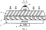
на фиг.2 приведена схема расположения гидротурбин.figure 2 shows the arrangement of hydraulic turbines.
Биротативный электрогенератор, предназначенный для питания скважинной аппаратуры, установлен в колонне бурильных труб или в обсадной колонне и содержит, по меньшей мере, одно устройство крепления генератора 1 на статоре 2. В устройстве крепления электрогенератора 1 выполнены отверстия «Б» для прохода бурового раствора.A biotic generator designed to power the downhole equipment is installed in the drill pipe string or in the casing and contains at least one device for attaching the generator 1 to the stator 2. In the device for attaching the generator 1, holes “B” are made for drilling fluid passage.
Биротативный электрогенератор содержит внешний ротор 3 с задней гидротурбиной 4 и внутренний ротор 5 с передней гидротурбиной 6, т.е гидротурбина выполнена двухступенчатой биротативной. Передняя гидротурбина 6 имеет наклонно-установленные плоские лопатки, установленные под углом 20...45°, а лопатки гидротурбины 4 выполнены профилированными для того, чтобы эффективнее сработать перепад давления на гидротурбинах, т.к. выполнение обеих турбин одинаковыми не позволило бы сработать перепад на второй по потоку, т.е. задней турбине 4.The biirotational electric generator contains an
Статор 2 имеет в нижней части электрический разъем 7, а внутри статора 2 установлена обмотка возбуждения 8.The stator 2 has an electrical connector 7 at the bottom, and an excitation winding 8 is installed inside the stator 2.
Генератор имеет две магнитопроницаемые перегородки - верхнюю 9 и нижнюю 10, которые отделяют внешний ротор 3 от статора 2 и создают негерметичную полость внешнего ротора «В» и внутреннюю полость статора «Г». По обе стороны от немагнитных перегородок - верхней 9 и нижней 10 расположены магниты двух торцовых магнитных муфт, а именно: внутренней и внешней, конкретно ведомые магниты внутренней и внешней муфт, соответственно поз.11 и 12. Магниты 11 установлены на верхнем валу 13, а магниты 12 установлены на роторе 5, который установлен на подшипнике 14 в стакане 15. Герметичная полость ротора «Д» заполнена смазывающей жидкостью. Заправка смазывающей жидкостью полости «Д» осуществляется через канал «Е», закрытый при работе винтом 16. Полость «В» сообщается с внешней средой посредством отверстия «Ж». Внутри статора 2 у его верхнего торца около немагнитной перегородки 9 установлены ведомые магниты внутренней и внешней торцовых муфт 16 и 17, соответственно. На нижнем валу 18 установлены магниты возбуждения 19, а на нижнем промежуточном валу 20 установлена обмотка возбуждения 8. Нижний вал 18 установлен в подшипниках 21 и 22, а промежуточный вал 20 на подшипниках 21 и 23. Нижний вал 19 имеет упорный бурт 24, под которым установлены токосъемные кольца 25, с которыми контактируют токосъемники 26. Провода 27 через отверстия «Д» соединены с электрическим разъемом 7 и загерметизированы компаундом 28. Для заправки полости «Г» компенсаторной жидкостью служит отверстие в статоре генератора 2, закрытое пробкой 29.The generator has two magnetically permeable partitions - the upper 9 and lower 10, which separate the
Гидротурбины 4 и 6 установлены рядом, на расстоянии 2 ... 5 мм друг от друга в передней части генератора, для более полного срабатывания перепада давления за счет профилирования лопаток турбины 4 и 6 с разным углом установки лопаток. Гидротурбина 6 является одновременно сопловым аппаратом для гидротурбины 4 (фиг.3). Это позволяет отказаться от применения сопловых аппаратов, что упростит сборку генератора и уменьшит его диаметральные габариты и вес электрогенератора.Hydroturbines 4 and 6 are installed side by side, at a distance of 2 ... 5 mm from each other in the front of the generator, for a more complete operation of the pressure drop due to the profiling of the
Внутренняя полость статора «Г» и герметичная полость «Д» заполнены смазывающей жидкостью. Отверстие «Е» для заправки герметичной полости «Д» смазывающей жидкостью выполнено в верхней части внутреннего ротора 5 и закрыто винтом 16.The internal stator cavity "G" and the sealed cavity "D" are filled with lubricating fluid. The hole "E" for filling the sealed cavity "D" with lubricating fluid is made in the upper part of the
Полость «Ж», в которой находятся обмотка возбуждения 8 и возбуждающие магниты 8, заполнена компенсаторной жидкостью. Компенсаторная жидкость имеет удельный объемный коэффициент расширения, равный удельному объемному коэффициенту расширения металла, из которого выполнен статор 2, при этом компенсаторная жидкость не обязательно должна иметь смазывающие свойства.The cavity "G" in which the excitation winding 8 and the exciting magnets 8 are located is filled with a compensating liquid. The compensating liquid has a specific volume expansion coefficient equal to the specific volume expansion coefficient of the metal from which the stator 2 is made, while the compensating liquid does not have to have lubricating properties.
На статоре 2 в нижней части выполнено заправочное отверстие для компенсаторной жидкости, закрытое винтом 29.On the stator 2 in the lower part there is a filling hole for the compensating liquid, closed by a screw 29.
При работе генератора буровой раствор проходит через гидротурбины 6 и 4, которые начинают вращаться с ротором 3 и верхним внутренним валом 13 в разные стороны.When the generator is operating, the drilling fluid passes through the
Первая по потоку гидротурбина 6 будет выполнять роль соплового аппарата для второй по потоку гидротурбины 4. Это позволит упростить сборку генератора, отказаться от применения направляющих аппаратов и увеличить КПД и мощность турбины. Также появилась возможность значительно уменьшить диаметральные габариты генератора или увеличить его мощность примерно в 2 раза при тех же габаритах и весе. Это позволит спроектировать скважинные приборы для бурильных и обсадных колонн малого диаметра. Применение проводов для передачи электрической энергии, размещенных в отверстиях «И» статора 2, позволит вывести значительную мощность с использованием скользящих токосъемников 26. Генератор со скважинным прибором забойной телеметрической системы может устанавливаться в бурильную или обсадную колонну, собранную из труб длиной до 10-12 м, т.е. ограничение по длине не критично, в отличие от ограничений по диаметру. Диаметр компоновки: генератор-скважинный прибор строго ограничен диаметром колонны. Электроэнергия по проводам 27 передается от обмотки возбуждения 8 электрическому разъему 7. Электрический разъем 7 предпочтительно выполнить коаксиальным, это позволит отказаться от угловой ориентации электрогенератора внутри колонны бурильных или обсадных труб при его стыковке со скважинным прибором (на фиг.1-3 скважинный прибор не показан).The
Применение изобретения позволило:The application of the invention allowed:
1. Значительно уменьшить диаметральные габариты и вес биротативного электрогенератора за счет применения биротативной турбины и увеличения его длины на длину магнитной муфты.1. Significantly reduce the diametric dimensions and weight of the birobotative electric generator through the use of the birobative turbine and increase its length by the length of the magnetic coupling.
2. Увеличить мощность и напряжение на электрических выводах электрогенератора за счет применения биротативной турбины.2. To increase the power and voltage at the electrical terminals of the generator through the use of a biotic turbine.
3. Значительно увеличить ресурс работы опор за счет применения многоопорных схем, уменьшения диаметра двух уплотнений до минимально-возможного, т.е. до диаметра вала и минимизации скорости проскальзывания верхнего уплотнения по валу относительно вала практически до нуля.3. Significantly increase the service life of the supports due to the use of multi-bearing schemes, reducing the diameter of two seals to the minimum possible, ie to the shaft diameter and to minimize the sliding speed of the upper seal on the shaft relative to the shaft to almost zero.
4. Уменьшить дисбаланс ротора биротативного электрогенератора за счет уменьшения их диаметра в 1,5-2,0 раза.4. To reduce the imbalance of the rotor of the birotative electric generator by reducing their diameter by 1.5-2.0 times.
5. Повысить надежность уплотнения полости биротативного электрогенератора за счет отделения масляной полости «Д» от полости с компенсаторной жидкостью «Г» с объемным коэффициентом температурного расширения, равным объемному коэффициенту температурного расширения металла, из которого выполнен статор, и отказа от компенсатора температурного расширения, без которого электрогенераторы в забое обычно не применяются.5. To increase the reliability of sealing the cavity of the birobotative electric generator by separating the oil cavity “D” from the cavity with the compensating liquid “G” with a volume coefficient of thermal expansion equal to the volume coefficient of thermal expansion of the metal from which the stator is made, and failure of the expansion valve, without which electric generators in the face are usually not used.
6. Упростить конструкцию биротативного электрогенератора, за счет отказа от применения направляющих аппаратов турбины и максимального упрощения конструкции уплотнения.6. To simplify the design of the birobotative electric generator, due to the rejection of the use of turbine guides and the maximum simplification of the seal design.
7. Упростить сборку и разборку биротативного электрогенератора за счет выполнения модульной конструкции и применения коаксиального электрического разъема.7. To simplify the assembly and disassembly of the birobotative electric generator through the implementation of a modular design and the use of a coaxial electrical connector.
8. Улучшить ремонтопригодность биротативного электрогенератора за счет предельно простой конструкции, минимального числа деталей и простой конфигурации всех деталей.8. Improve the maintainability of the birotative electric generator due to the extremely simple design, the minimum number of parts and the simple configuration of all parts.
Claims (6)
Priority Applications (1)
| Application Number | Priority Date | Filing Date | Title |
|---|---|---|---|
| RU2007103683/09A RU2321744C1 (en) | 2007-01-30 | 2007-01-30 | Birotatory generator |
Applications Claiming Priority (1)
| Application Number | Priority Date | Filing Date | Title |
|---|---|---|---|
| RU2007103683/09A RU2321744C1 (en) | 2007-01-30 | 2007-01-30 | Birotatory generator |
Publications (1)
| Publication Number | Publication Date |
|---|---|
| RU2321744C1 true RU2321744C1 (en) | 2008-04-10 |
Family
ID=39366783
Family Applications (1)
| Application Number | Title | Priority Date | Filing Date |
|---|---|---|---|
| RU2007103683/09A RU2321744C1 (en) | 2007-01-30 | 2007-01-30 | Birotatory generator |
Country Status (1)
| Country | Link |
|---|---|
| RU (1) | RU2321744C1 (en) |
Cited By (3)
| Publication number | Priority date | Publication date | Assignee | Title |
|---|---|---|---|---|
| RU2442890C2 (en) * | 2010-10-11 | 2012-02-20 | Николай Борисович Болотин | Well generator |
| RU2453698C2 (en) * | 2010-02-24 | 2012-06-20 | Николай Борисович Болотин | Downhole generator |
| RU221661U1 (en) * | 2023-04-05 | 2023-11-16 | Общество с ограниченной ответственностью "БИТАС" | TURBO GENERATOR FOR POWERING WELL EQUIPMENT |
-
2007
- 2007-01-30 RU RU2007103683/09A patent/RU2321744C1/en active
Non-Patent Citations (1)
| Title |
|---|
| МОЛЧАНОВ А.А., СИРАЕВ А.Х. Скважные автономные системы с магнитной регистрацией. - М.: Недра, 1979, с.102, 103. * |
Cited By (3)
| Publication number | Priority date | Publication date | Assignee | Title |
|---|---|---|---|---|
| RU2453698C2 (en) * | 2010-02-24 | 2012-06-20 | Николай Борисович Болотин | Downhole generator |
| RU2442890C2 (en) * | 2010-10-11 | 2012-02-20 | Николай Борисович Болотин | Well generator |
| RU221661U1 (en) * | 2023-04-05 | 2023-11-16 | Общество с ограниченной ответственностью "БИТАС" | TURBO GENERATOR FOR POWERING WELL EQUIPMENT |
Similar Documents
| Publication | Publication Date | Title |
|---|---|---|
| RU2421612C1 (en) | Multi-phase power generator of downhole equipment | |
| RU2321744C1 (en) | Birotatory generator | |
| RU2331149C1 (en) | Borehole electric generator | |
| RU2334340C1 (en) | Drilling electric generator | |
| RU2325519C1 (en) | Borehole birotatory electric generator | |
| RU2324815C1 (en) | Well electric generator | |
| RU2329377C1 (en) | Birotating power generator | |
| RU2321743C1 (en) | Birotatory generator | |
| RU2321742C1 (en) | Electric generator | |
| RU2321741C1 (en) | Autonomous electric generator | |
| RU2334099C1 (en) | Power generator for well equipment | |
| RU2324808C1 (en) | Power generator of well logging equipment | |
| RU2417311C1 (en) | Electro-generator of power supply for borehole equipment | |
| RU2418348C1 (en) | Electric power generator of downhole telemetric system | |
| RU2264537C1 (en) | Generator | |
| RU2337240C1 (en) | Downhole electric generator | |
| RU2417313C1 (en) | Generator of power supply for borehole equipment | |
| RU2333352C1 (en) | Borehole equipment supply generator | |
| RU2332564C1 (en) | Borehole telemetry system power supply generator | |
| RU2426875C1 (en) | Borehole generator | |
| RU2326238C1 (en) | Birotatory borehole electric generator | |
| RU2333353C1 (en) | Supply turbo generator for borehole equipment | |
| RU2432461C1 (en) | High-voltage borehole generator | |
| RU2442892C1 (en) | Well generator | |
| RU2419719C1 (en) | Birotary electric generator for power supply to downhole instrument |