RU2320373C2 - Device for manual metering of medical-purpose liquid matter, in particular, of bone cement - Google Patents
Device for manual metering of medical-purpose liquid matter, in particular, of bone cement Download PDFInfo
- Publication number
- RU2320373C2 RU2320373C2 RU2005101754/14A RU2005101754A RU2320373C2 RU 2320373 C2 RU2320373 C2 RU 2320373C2 RU 2005101754/14 A RU2005101754/14 A RU 2005101754/14A RU 2005101754 A RU2005101754 A RU 2005101754A RU 2320373 C2 RU2320373 C2 RU 2320373C2
- Authority
- RU
- Russia
- Prior art keywords
- handle
- plunger
- chamber
- screw
- internal thread
- Prior art date
Links
Images
Classifications
-
- B—PERFORMING OPERATIONS; TRANSPORTING
- B05—SPRAYING OR ATOMISING IN GENERAL; APPLYING FLUENT MATERIALS TO SURFACES, IN GENERAL
- B05C—APPARATUS FOR APPLYING FLUENT MATERIALS TO SURFACES, IN GENERAL
- B05C17/00—Hand tools or apparatus using hand held tools, for applying liquids or other fluent materials to, for spreading applied liquids or other fluent materials on, or for partially removing applied liquids or other fluent materials from, surfaces
- B05C17/005—Hand tools or apparatus using hand held tools, for applying liquids or other fluent materials to, for spreading applied liquids or other fluent materials on, or for partially removing applied liquids or other fluent materials from, surfaces for discharging material from a reservoir or container located in or on the hand tool through an outlet orifice by pressure without using surface contacting members like pads or brushes
- B05C17/01—Hand tools or apparatus using hand held tools, for applying liquids or other fluent materials to, for spreading applied liquids or other fluent materials on, or for partially removing applied liquids or other fluent materials from, surfaces for discharging material from a reservoir or container located in or on the hand tool through an outlet orifice by pressure without using surface contacting members like pads or brushes with manually mechanically or electrically actuated piston or the like
- B05C17/0116—Hand tools or apparatus using hand held tools, for applying liquids or other fluent materials to, for spreading applied liquids or other fluent materials on, or for partially removing applied liquids or other fluent materials from, surfaces for discharging material from a reservoir or container located in or on the hand tool through an outlet orifice by pressure without using surface contacting members like pads or brushes with manually mechanically or electrically actuated piston or the like characterised by the piston driving means
- B05C17/0133—Nut and bolt advancing mechanism, e.g. threaded piston rods
-
- A—HUMAN NECESSITIES
- A61—MEDICAL OR VETERINARY SCIENCE; HYGIENE
- A61B—DIAGNOSIS; SURGERY; IDENTIFICATION
- A61B17/00—Surgical instruments, devices or methods
- A61B17/56—Surgical instruments or methods for treatment of bones or joints; Devices specially adapted therefor
- A61B17/58—Surgical instruments or methods for treatment of bones or joints; Devices specially adapted therefor for osteosynthesis, e.g. bone plates, screws or setting implements
- A61B17/88—Osteosynthesis instruments; Methods or means for implanting or extracting internal or external fixation devices
- A61B17/8802—Equipment for handling bone cement or other fluid fillers
- A61B17/8805—Equipment for handling bone cement or other fluid fillers for introducing fluid filler into bone or extracting it
- A61B17/8822—Equipment for handling bone cement or other fluid fillers for introducing fluid filler into bone or extracting it characterised by means facilitating expulsion of fluid from the introducer, e.g. a screw pump plunger, hydraulic force transmissions, application of vibrations or a vacuum
-
- A—HUMAN NECESSITIES
- A61—MEDICAL OR VETERINARY SCIENCE; HYGIENE
- A61B—DIAGNOSIS; SURGERY; IDENTIFICATION
- A61B90/00—Instruments, implements or accessories specially adapted for surgery or diagnosis and not covered by any of the groups A61B1/00 - A61B50/00, e.g. for luxation treatment or for protecting wound edges
- A61B90/06—Measuring instruments not otherwise provided for
- A61B2090/063—Measuring instruments not otherwise provided for for measuring volume
-
- A—HUMAN NECESSITIES
- A61—MEDICAL OR VETERINARY SCIENCE; HYGIENE
- A61F—FILTERS IMPLANTABLE INTO BLOOD VESSELS; PROSTHESES; DEVICES PROVIDING PATENCY TO, OR PREVENTING COLLAPSING OF, TUBULAR STRUCTURES OF THE BODY, e.g. STENTS; ORTHOPAEDIC, NURSING OR CONTRACEPTIVE DEVICES; FOMENTATION; TREATMENT OR PROTECTION OF EYES OR EARS; BANDAGES, DRESSINGS OR ABSORBENT PADS; FIRST-AID KITS
- A61F2/00—Filters implantable into blood vessels; Prostheses, i.e. artificial substitutes or replacements for parts of the body; Appliances for connecting them with the body; Devices providing patency to, or preventing collapsing of, tubular structures of the body, e.g. stents
- A61F2/02—Prostheses implantable into the body
- A61F2/30—Joints
- A61F2/44—Joints for the spine, e.g. vertebrae, spinal discs
-
- A—HUMAN NECESSITIES
- A61—MEDICAL OR VETERINARY SCIENCE; HYGIENE
- A61F—FILTERS IMPLANTABLE INTO BLOOD VESSELS; PROSTHESES; DEVICES PROVIDING PATENCY TO, OR PREVENTING COLLAPSING OF, TUBULAR STRUCTURES OF THE BODY, e.g. STENTS; ORTHOPAEDIC, NURSING OR CONTRACEPTIVE DEVICES; FOMENTATION; TREATMENT OR PROTECTION OF EYES OR EARS; BANDAGES, DRESSINGS OR ABSORBENT PADS; FIRST-AID KITS
- A61F2/00—Filters implantable into blood vessels; Prostheses, i.e. artificial substitutes or replacements for parts of the body; Appliances for connecting them with the body; Devices providing patency to, or preventing collapsing of, tubular structures of the body, e.g. stents
- A61F2/02—Prostheses implantable into the body
- A61F2/30—Joints
- A61F2/46—Special tools for implanting artificial joints
- A61F2/4601—Special tools for implanting artificial joints for introducing bone substitute, for implanting bone graft implants or for compacting them in the bone cavity
-
- A—HUMAN NECESSITIES
- A61—MEDICAL OR VETERINARY SCIENCE; HYGIENE
- A61F—FILTERS IMPLANTABLE INTO BLOOD VESSELS; PROSTHESES; DEVICES PROVIDING PATENCY TO, OR PREVENTING COLLAPSING OF, TUBULAR STRUCTURES OF THE BODY, e.g. STENTS; ORTHOPAEDIC, NURSING OR CONTRACEPTIVE DEVICES; FOMENTATION; TREATMENT OR PROTECTION OF EYES OR EARS; BANDAGES, DRESSINGS OR ABSORBENT PADS; FIRST-AID KITS
- A61F2/00—Filters implantable into blood vessels; Prostheses, i.e. artificial substitutes or replacements for parts of the body; Appliances for connecting them with the body; Devices providing patency to, or preventing collapsing of, tubular structures of the body, e.g. stents
- A61F2/02—Prostheses implantable into the body
- A61F2/30—Joints
- A61F2/46—Special tools for implanting artificial joints
- A61F2/4657—Measuring instruments used for implanting artificial joints
- A61F2002/4663—Measuring instruments used for implanting artificial joints for measuring volumes or other three-dimensional shapes
Landscapes
- Health & Medical Sciences (AREA)
- Engineering & Computer Science (AREA)
- Orthopedic Medicine & Surgery (AREA)
- Surgery (AREA)
- Life Sciences & Earth Sciences (AREA)
- Animal Behavior & Ethology (AREA)
- Public Health (AREA)
- Heart & Thoracic Surgery (AREA)
- Medical Informatics (AREA)
- Molecular Biology (AREA)
- Nuclear Medicine, Radiotherapy & Molecular Imaging (AREA)
- General Health & Medical Sciences (AREA)
- Biomedical Technology (AREA)
- Veterinary Medicine (AREA)
- Mechanical Engineering (AREA)
- Surgical Instruments (AREA)
- Infusion, Injection, And Reservoir Apparatuses (AREA)
- Prostheses (AREA)
- Apparatus For Radiation Diagnosis (AREA)
- Materials For Medical Uses (AREA)
- Curing Cements, Concrete, And Artificial Stone (AREA)
Abstract
Description
Область техники, к которой относится изобретениеFIELD OF THE INVENTION
Настоящее изобретение относится к устройствам для ручного дозирования текучего вещества медицинского назначения, например медицинского материала в жидком или пастообразном состоянии, костного цемента, гипса или аналогичного материала.The present invention relates to devices for manual dosing of a fluid substance for medical use, for example, medical material in a liquid or pasty state, bone cement, gypsum or similar material.
Устройство в соответствии с настоящим изобретением, в предпочтительном варианте, находит практическое применение в вертебральной реконструктивной хирургии и других областях медицинского лечения и, в общем, во всех областях медицины, в которых необходимо доставлять и управляемым образом дозировать материал, который находится в вязкотекучем или вязком состоянии и должным образом приготовлен для лекарственной терапии, процедур или хирургических операций.The device in accordance with the present invention, in a preferred embodiment, finds practical application in vertebral reconstructive surgery and other areas of medical treatment and, in General, in all areas of medicine in which it is necessary to deliver and in a controlled manner to dose material that is in a viscous or viscous state and properly prepared for drug therapy, procedures, or surgeries.
Уровень техникиState of the art
Дозирующие устройства вышеуказанного типа известны и, в общем случае, содержат, по существу, цилиндрическую дозирующую камеру с выпускным отверстием для дозируемого текучего вещества или полимера, захватной рукояткой, которая может быть закреплена на дозирующей камере, и шток с плунжером, заключенные в дозирующую камеру для вытеснения текучего вещества через выпускное отверстие. Плунжер находится на продольном конце штока, который содержит на противоположном конце исполнительный элемент, который пользователем может быть приведен в действие вручную.Dosing devices of the above type are known and, in general, comprise a substantially cylindrical dosing chamber with an outlet for a dosing fluid or polymer, a gripping handle that can be attached to the dosing chamber, and a rod with a plunger enclosed in a dosing chamber for displacing the fluid through the outlet. The plunger is located on the longitudinal end of the rod, which contains at the opposite end an actuating element that can be manually actuated by the user.
Чтобы можно было осуществлять точное дозирование под давлением, в частности, когда текущее вещество находится в пастообразной форме или обладает высокой вязкостью, предусмотрено винтовое приводное приспособление, по существу, состоящее из резьбы, которая выполнена на внешней поверхности штока с плунжером и предназначена для взаимодействия с внутренней резьбой, относящейся к дозирующей камере. При приведении нарезного штока во вращение посредством исполнительного элемента, плунжер приводится в движение вдоль дозирующей камеры и вызывает управляемое вытеснение полимера.In order to be able to accurately dispense under pressure, in particular when the flowing substance is in a pasty form or has a high viscosity, a screw drive device is provided, essentially consisting of a thread, which is made on the outer surface of the stem with a plunger and is designed to interact with the inner thread related to the metering chamber. When the threaded rod is brought into rotation by means of an actuating element, the plunger is driven along the dosing chamber and causes controlled displacement of the polymer.
Пример дозирующего устройства вышеупомянутого типа приведен в заявке № DE-A-3443167, поданной в Германии. Недостаток данного известного устройства состоит в том, что для заполнения дозирующей камеры на месте дозируемым полимером или костным цементом нарезной шток необходимо вращать в направлении, противоположном направлению вращения при инъецировании, что требует определенного времени, в течение которого полимер может, по меньшей мере, частично затвердевать с результирующим снижением его текучести и пластичности.An example of a metering device of the aforementioned type is given in application No. DE-A-3443167 filed in Germany. The disadvantage of this known device is that to fill the metering chamber in place with the dosed polymer or bone cement, the threaded rod must be rotated in the direction opposite to the direction of rotation during injection, which requires a certain time during which the polymer can at least partially harden with a resulting decrease in its fluidity and ductility.
Для предотвращения данной проблемы предложено несколько ручных дозирующих устройств такого типа, которые описаны в заявке на европейский патент № EP-A-1054231 и заявке № FR-A-2690332, поданной во Франции, в которых предлагается дозирующая камера с боковым отверстием - отличающимся от выпускного отверстия - для ввода подлежащего дозированию текучего вещества в камеру.To prevent this problem, several hand-held metering devices of this type are proposed, which are described in European Patent Application No. EP-A-1054231 and French Patent Application No. FR-A-2690332, in which a metering chamber with a side opening different from the outlet is proposed openings - for introducing the fluid to be dosed into the chamber.
Отверстие для ввода полимера присоединено соединительной трубкой к складскому баку или вспомогательному шприцу для ввода текучего вещества, который должен быть предварительно наполнен из одного из упомянутых вспомогательных контейнеров.The polymer injection hole is connected by a connecting tube to a storage tank or auxiliary syringe for introducing a fluid that must be pre-filled from one of the aforementioned auxiliary containers.
Недостаток данного известного прежнего решения состоит в его относительной сложности и больших размерах. Кроме того, процедура перекачивания текучего вещества в камеру весьма продолжительна и трудоемка и может привести в частичному затвердеванию упомянутого полимера.The disadvantage of this known previous solution is its relative complexity and large size. In addition, the procedure for pumping a fluid into the chamber is very lengthy and time-consuming and can lead to partial hardening of the aforementioned polymer.
Устройства дозирования высоковязких текучих веществ, например гипса или мастик, известны по заявкам №№ US-A-4485944 и US-A-5253589, поданным в США, в которых можно переключаться с винтового привода плунжера на непосредственное приведение в движение в продольном направлении без применения винтовых приспособлений.Dosing devices for highly viscous fluid substances, such as gypsum or mastics, are known from US Pat. No. US-A-4485944 and US-A-5253589, filed in the USA, in which you can switch from a screw drive of the plunger to directly drive in the longitudinal direction without using screw devices.
Другое устройство данного типа, которое специально предназначено для выполнения операций в вертебральной реконструктивной хирургии, описано в заявке на европейский патент № EP-A-1157677 и содержит плунжер, который можно либо приводить в движение винтовым механизмом, либо просто перемещать в продольном направлении без использования винтового механизма. В частности, внутренняя резьба образована зубцами, которые входят в зацепление с нарезным штоком так, чтобы вращательное движение нарезного штока преобразовывалось в прямолинейное движение плунжера. Однако при отведении зубцов от нарезного штока данный шток можно свободно перемещать вдоль оси так, чтобы непосредственно оказывать давление на костный цемент. Для этого зубцы можно сдвигать внутрь захватной рукоятки против усилия пружины и можно отводить от нарезного штока и подводить к нему приведением в действие поперечного подвижного рабочего органа, который выступает из рукоятки.Another device of this type, which is specifically designed to perform operations in vertebral reconstructive surgery, is described in European patent application EP-A-1157677 and contains a plunger that can either be driven by a screw mechanism or simply moved in the longitudinal direction without using a screw mechanism. In particular, the internal thread is formed by teeth that engage with the threaded rod so that the rotational movement of the threaded rod is converted into a rectilinear movement of the plunger. However, when the teeth are removed from the threaded rod, this rod can be freely moved along the axis so as to directly exert pressure on the bone cement. To do this, the teeth can be shifted into the gripping handle against the force of the spring and can be retracted from the threaded rod and brought to it by actuating the transverse movable working body, which protrudes from the handle.
Благодаря описанной конфигурации, после приведения в действие подвижного рабочего органа для отвода зубцов от нарезного штока, возможно создание давления на костный цемент внутри дозирующей камеры как в процессе всасывания, так и в процессе инъекции, как в случае с обычным шприцом. С данного момента, после подвода зубцов к нарезному штоку приведением в действие подвижного рабочего органа, можно выполнять микрометрическую подачу плунжера вращением исполнительного элемента.Due to the described configuration, after actuating the movable working body to divert the teeth from the threaded rod, it is possible to create pressure on the bone cement inside the dosing chamber both during the suction process and during the injection, as in the case of a conventional syringe. From this moment, after the supply of the teeth to the threaded rod by actuating the movable working body, it is possible to perform micrometric feed of the plunger by rotation of the actuating element.
Основной недостаток данного известного устройства состоит в существенной конструктивной сложности механизма, приводящего в движение зубцы, а также большое число деталей, что обуславливает высокую стоимость устройства в целом.The main disadvantage of this known device is the significant structural complexity of the mechanism that drives the teeth, as well as a large number of parts, which leads to the high cost of the device as a whole.
С точки зрения затрат данная высокая стоимость делает невыгодным однократное применение устройства и тем самым приводит к необходимости производить очистку и стерилизацию устройства в автоклаве или использовать другие способы при каждом применении данного устройства, в результате чего требуется использовать материалы высокого качества и/или с высокой стойкостью к нагреванию и процедурам стерилизации.From the point of view of costs, this high cost makes it unprofitable to use the device once, and thus leads to the need to clean and sterilize the device in an autoclave or to use other methods each time this device is used, as a result of which it is necessary to use high quality materials and / or with high resistance to heating and sterilization procedures.
Другой и, возможно, более серьезный недостаток состоит в необходимости перемещения подвижного рабочего органа одним пальцем руки в то время, как другие пальцы сжимают рукоятку, что затрудняет операцию расцепления зубцов, особенно когда на рабочем месте присутствуют текучие среды и влага.Another and possibly more serious drawback is the need to move the movable working body with one finger while the other fingers squeeze the handle, which complicates the operation of disengaging the teeth, especially when fluids and moisture are present in the workplace.
Поэтому существует возможность, что врач или хирург, чьи руки обычно в крови или других биологических жидкостях, не сможет легко привести в действие подвижный рабочий орган и будет вынужден просить помощи или пользоваться другой рукой в условиях, когда необходимо действовать быстро, в том числе потому, что цемент твердеет всего за несколько минут.Therefore, it is possible that a doctor or surgeon, whose hands are usually in blood or other body fluids, will not be able to easily activate a mobile working body and will be forced to ask for help or use the other hand in conditions where it is necessary to act quickly, including because that cement hardens in just a few minutes.
Последний, но не менее важный недостаток состоит в том, что данное известное устройство содержит подвижный рабочий орган всего с одной стороны, в частности с левой стороны, чтобы нарезной шток можно было приводить в движение правой рукой, и потому не пригодно для удобного использования левшой.The last, but no less important drawback is that this known device contains a movable working body on only one side, in particular on the left side, so that the threaded rod can be moved with the right hand, and therefore is not suitable for convenient use by a left-handed person.
Было бы удобнее работать с дозирующим устройством, которое является более функциональным и облегчает обращение с ним по сравнению с известными дозирующими устройствами во всех условиях применения любым пользователем.It would be more convenient to work with a metering device, which is more functional and easier to handle compared with known metering devices in all conditions of use by any user.
Кроме того, желательно наличие дозирующего устройства с намного более простой конструкцией, чтобы существенно сократить его себестоимость. Таким образом, после первого применения данного устройства в максимально гигиенических и безопасных условиях дозирующее устройство можно выбросить, что исключает трудоемкие и дорогие процедуры очистки и стерилизации.In addition, it is desirable to have a metering device with a much simpler design in order to significantly reduce its cost. Thus, after the first use of this device in the most hygienic and safe conditions, the dosing device can be discarded, which eliminates the time-consuming and expensive cleaning and sterilization procedures.
Сущность изобретенияSUMMARY OF THE INVENTION
Основная задача настоящего изобретения заключается в создании усовершенствованного дозирующего устройства, которое позволяет осуществлять микрометрическое дозирование текучего вещества под высоким давлением, может служить как обычный шприц и характеризуется высокой эффективностью и удобством в обращении при работе всего одной рукой.The main objective of the present invention is to provide an improved metering device, which allows micrometric dosing of a fluid substance under high pressure, can serve as a regular syringe and is characterized by high efficiency and ease of use with just one hand.
Другая задача заключается в создании дозирующего устройства, обладающего исключительно простой и соответственно дешевой конструкцией, позволяющей выбрасывать данное устройство после однократного применения.Another task is to create a metering device with an extremely simple and accordingly cheap design that allows you to throw this device after a single use.
Последняя, но не менее важная задача заключается в создании дозирующего устройства, которое можно изготовить из недорогих материалов и с использованием деталей, которые можно легко приобрести на рынке, чтобы обеспечить пригодность данного устройства для разового применения.Last but not least, the task is to create a metering device that can be made from inexpensive materials and using parts that can be easily purchased on the market to ensure the suitability of this device for single use.
Указанные и другие задачи изобретения, которые очевидны из приведенного ниже описания, решаются с помощью устройства для ручной инъекции текучих веществ медицинского назначения, например твердеющего полимера типа костного цемента, которое содержит в соответствии с п.1 формулы изобретения дозирующую камеру с концевым отверстием, захватную рукоятку, плунжер, который заключен в упомянутую камеру и снабжен исполнительным элементом для пользователя, и винтовое приводное приспособление, расположенное между упомянутым исполнительным элементом и упомянутым плунжером так, чтобы исполнять продольное перемещение данного плунжера и оказывать давление на дозируемое текучее вещество, при этом упомянутое винтовое приспособление способно к видоизменению для того, чтобы выполнялось переключение из рабочей конфигурации, в которой осуществляется микрометрическая подача плунжера, в нерабочую конфигурацию, в которой плунжер можно перемещать свободно, отличающегося тем, что упомянутое винтовое приспособление содержит наружную резьбу, относящуюся к упомянутому плунжеру, и элемент с внутренней резьбой, выполненный за одно целое с упомянутой рукояткой, при этом упомянутая рукоятка способна упруго деформироваться под действием поперечного сжатия, чтобы переключать упомянутое винтовое приспособление из упомянутой рабочей конфигурации в упомянутую нерабочую конфигурацию.These and other objectives of the invention, which are obvious from the description below, are solved using a device for manual injection of medical fluids, for example, a hardening polymer such as bone cement, which contains, in accordance with claim 1, a metering chamber with an end hole, a gripping handle , a plunger which is enclosed in said chamber and provided with an actuating element for the user, and a screw driving device located between said actuating element and the said plunger so as to perform a longitudinal movement of the plunger and exert pressure on the fluid to be dosed, while the said screw device is capable of modification in order to switch from the working configuration, in which the plunger is micrometered, to the non-working configuration, to wherein the plunger can be moved freely, characterized in that said screw device comprises an external thread related to said plunger and an element internally threaded integrally with said handle, wherein said handle is capable of elastically deforming under transverse compression to switch said screw device from said working configuration to said non-working configuration.
Благодаря данной конфигурации устройство в соответствии с настоящим изобретением обладает исключительно простой конструкцией, которая позволяет переключать данное устройство из конфигурации, предназначенной для микрометрической подачи, в конфигурацию простого ручного шприца, при этом исключительно простая конструкция и исключительно низкая себестоимость позволяют исключить повторное использование данного устройства.Due to this configuration, the device in accordance with the present invention has an extremely simple design that allows you to switch this device from a configuration intended for micrometric feeding, in the configuration of a simple hand-held syringe, while the extremely simple design and extremely low cost allow to exclude reuse of this device.
Краткое описание чертежейBrief Description of the Drawings
Другие признаки и преимущества настоящего изобретения очевидны из следующего ниже подробного описания предпочтительных, но не исключительных вариантов осуществления устройства для ручного дозирования текучего вещества, проиллюстрированных неограничивающим примером со ссылками на прилагаемые чертежи, на которых:Other features and advantages of the present invention are apparent from the following detailed description of preferred, but not exclusive embodiments of a device for manually dispensing a fluid, illustrated by a non-limiting example with reference to the accompanying drawings, in which:
Фиг.1 - общий вид инъекционного устройства в процессе использования при вертебральной реконструктивной хирургической операции,Figure 1 is a General view of the injection device in use during vertebral reconstructive surgery,
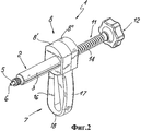
Фиг.2 - общий вид в аксонометрии первого варианта осуществления устройства, показанного на фиг.1, в собранном состоянии,Figure 2 is a General view in perspective view of the first embodiment of the device shown in figure 1, in the assembled state,
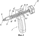
Фиг.3 - общий вид в аксонометрии устройства, показанного на фиг.2, с частичным разрезом и с некоторыми деталями, снятыми для более наглядного представления компонентов,Figure 3 is a General view in a perspective view of the device shown in figure 2, with a partial section and with some details, taken for a more visual representation of the components,
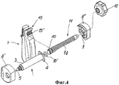
Фиг.4 - покомпонентное изображение в аксонометрии устройства, показанного на фиг.2,Figure 4 is an exploded perspective view of the device of Figure 2,
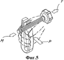
Фиг.5 - аксонометрическое изображение подузла устройства, показанного на фиг.2, без некоторых компонентов, снятых для более ясного объяснения функционирования устройства,Figure 5 is a perspective view of a subassembly of the device shown in figure 2, without some components, removed for a clearer explanation of the operation of the device,
Фиг.6 - вид сбоку устройства, показанного на фиг.2, с частичным разрезом по продольной осевой плоскости,6 is a side view of the device shown in figure 2, with a partial section along the longitudinal axial plane,
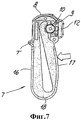
Фиг.7 - вид спереди устройства, показанного на фиг.2, с частичным разрезом по плоскости, указанной линией VI-VI, показанной на фиг.5,Fig.7 is a front view of the device shown in Fig.2, with a partial section along the plane indicated by line VI-VI shown in Fig.5,
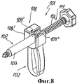
Фиг.8 - общий вид в аксонометрии второго варианта осуществления устройства, показанного на фиг.1, в собранном состоянии,Fig.8 is a General view in perspective view of a second embodiment of the device shown in Fig.1, in the assembled state,
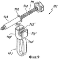
Фиг.9 - аксонометрическое изображение устройства, показанного на фиг.8, с некоторыми деталями, изображенными отдельно от остальной части устройства.Fig.9 is a perspective view of the device shown in Fig.8, with some details shown separately from the rest of the device.
Подробное описание некоторых предпочтительных вариантов осуществленияDetailed Description of Some Preferred Embodiments
На фиг.1 показано дозирующее устройство в соответствии с настоящим изобретением, обозначенное в общем позицией 1 и предназначенное для ручной инъекции текучего вещества, например полиакрилата или костного цемента, в труднодоступное место, например во внутреннюю полость позвонка, через тонкую трубку H, соединенную с иглой N.Figure 1 shows a dispensing device in accordance with the present invention, indicated generally by 1 and for the manual injection of a fluid substance, for example polyacrylate or bone cement, into a hard-to-reach place, for example, in the inner cavity of the vertebra, through a thin tube H connected to a needle N.
Нижеописанное устройство пригодно, в частности, для ортопедических хирургических операций, известных как вертебральная реконструктивная хирургия, для лечения или восстановления непрерывности позвонка V, подверженного травмам или болезням. Однако очевидно, что данное устройство можно применить для других видов лечения или хирургических или медицинских операций с использованием текучих сред разной плотности или вязкости или в других технологических областях, без выхода за пределы объема настоящего изобретения.The device described below is particularly suitable for orthopedic surgeries known as vertebral reconstructive surgery, for treating or restoring the continuity of a vertebra V which is prone to injuries or diseases. However, it is obvious that this device can be used for other types of treatment or surgical or medical operations using fluids of different densities or viscosities or in other technological fields, without going beyond the scope of the present invention.
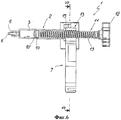
На фиг.2-7 представлен первый вариант осуществления устройства 1, которое содержит дозирующую камеру 2, имеющую, по существу, цилиндрическую боковую стенку 3 и предназначенную для наполнения твердеющим полимером или костным цементом.Figure 2-7 shows a first embodiment of a device 1, which contains a
Продольный конец боковой стенки 3 камеры открыт и ужесточен радиальным фланцем 4. Другой конец выполнен с сужением или содержит воронкообразную трубку 5 с отверстием 6 для пропуска полимера. Иглу N можно подсоединять к воронкообразной трубке 5 непосредственно или тонкой трубкой Н, чтобы перекачивать полимер к месту лечения.The longitudinal end of the
При необходимости дозирующую камеру 2 можно выполнить как корпус обычного шприца, изготовленного из полимерного материала такого типа, который широко доступен на рынке, чтобы сократить стоимость устройства в целом.If necessary, the
Рукоятка, обозначенная позицией 7, может быть соединена с камерой 2 посредством подходящего элемента 8 сопряжения, например, по существу, коробчатой формы, выполненного в виде двух противоположных корпусов 8′, 8′′, которые соединены между собой подходящими соединительными элементами 9 взаимно зацепляющегося типа или с использованием других связующих средств.The handle, indicated by 7, can be connected to the
В предпочтительном варианте стенки корпусов могут быть снабжены выступами, способными стабильно фиксировать рукоятку 7 в области байонетного поперечного выступа, относящегося к рукоятке, радиальным фланцем 4 жесткости стенки 3 дозирующей камеры 2.In a preferred embodiment, the walls of the housings may be provided with protrusions capable of stably fixing the
Плунжер 10 заключен внутри дозирующей камеры 2, при этом упомянутый поршень, при необходимости, снабжен уплотнительным кольцом, установлен на продольном конце штока 11, содержащего на его противоположном конце закрепленный шпонкой маховик или другой исполнительный элемент 12, который может захватывать пользователь, для облегчения вытеснения полимера, находящегося внутри камеры 2.The
Для удобства, чтобы приводить в движение шток 11 и вытеснять текучее или полимерное вещество, находящееся внутри камеры, высоким давлением и управляемым образом, предусмотрено винтовое приспособление, причем упомянутое винтовое приспособление в целом обозначено позицией 13 и содержит цилиндрическую резьбу 14, выполненную на цилиндрической поверхности штока 11, и элемент 15 с внутренней резьбой, который способен входить в зацепление с резьбой 14, но заблокирован от осевого и поворотного перемещений относительно стенки 3 камеры 2.For convenience, in order to drive the
Таким образом, чтобы исполнять микрометрическую подачу плунжера 10 с соответствующим дозированием инъецируемого цемента или текучего вещества, достаточно захватить маховик 12 и вращать его по часовой стрелке или против часовой стрелки, в зависимости от направления резьбы 14, чтобы тем самым приводить шток 11 в движение по оси и, следовательно, плунжер 10 в движение внутри камеры 2 в направлении по стрелке M.Thus, in order to perform micrometric feed of the
Чтобы создать возможность свободного скольжения плунжера 10 внутри камеры 2 без использования винтового приспособления 13 и тем самым ускорить выполнение операций наполнения камеры 2, винтовое приспособление 13 можно видоизменить так, чтобы выполнялось переключение из рабочей конфигурации в нерабочую конфигурацию и наоборот. В частности, элемент 15 с внутренней резьбой выполнен с цилиндрической частью с внутренней резьбой, которая может выходить из рабочей конфигурации - состояния зацепления с резьбой 14 нарезного штока 11, в котором допускается микрометрическая подача штока 10 - в нерабочую конфигурацию без контакта со штоком 11.In order to allow the
Таким образом, чтобы накачать полимер в камеру 2, достаточно вывести элемент 15 с внутренней резьбой из зацепления с резьбой 14 и потянуть нарезной шток в направлении по стрелке T за маховик 12.Thus, in order to pump the polymer into the
Кроме того, в случае слишком высокого давления полимера, инъецируемого в место оперативного вмешательства, можно моментально снизить давление выведением элемента 15 с внутренней резьбой из зацепления с резьбой 14 и тем самым созданием для плунжера 10 возможности отвода назад в камере 2.In addition, in the case of too high a pressure of the polymer injected into the surgical site, it is possible to instantly reduce the pressure by disengaging the
В соответствии с настоящим изобретением элемент 15 с внутренней резьбой выполнен за одно целое с рукояткой 7 в области, обращенной к нарезному штоку 11. Кроме того, рукоятку 7 можно упруго деформировать простым поперечным сжатием в направлении по стрелке P, чтобы переводить элемент 15 с внутренней резьбой в его нерабочую конфигурацию, т.е. отделять от резьбы 14 для предотвращения их взаимного зацепления.In accordance with the present invention, the
В предпочтительном варианте рукоятка 7 представляет собой, по существу, U-образный монолитный блок с первой продольной концевой частью 16, которая может быть присоединена к камере элементом 8 сопряжения, и с второй продольной концевой частью 17, содержащей элемент 15 с внутренней резьбой.In a preferred embodiment, the
Для удобства обе продольные концевые части 16, 17 упомянутого U-образного блока являются, по существу, жесткими и соединены упруго деформируемой промежуточной поперечной соединительной частью 18.For convenience, both
В частности, снабженная внутренней резьбой цилиндрическая часть элемента 15 с внутренней резьбой может быть выполнена на внешней стороне удлиненного рычага 17 упомянутого, по существу, U-образного блока.In particular, an internally threaded cylindrical portion of the threaded
Кроме того, в частности, продольные концевые части 16, 17 выполнены так, чтобы цилиндрическая часть элемента 15 с внутренней резьбой, в нормальном состоянии находилась в контакте с резьбой 14 штока 11 и могла быть отведена от упомянутого штока сведением продольных концевых частей 16, 17 рукоятки 7 в поперечном направлении ближе друг к другу.In addition, in particular, the
Для удобства углы продольных концевых частей 16, 17 и поперечной соединительной части 18 скруглены так, чтобы пользователь мог легко захватывать и сжимать рукоятку всеми пальцами одной руки, левой или правой, без затруднений даже в присутствии биологических жидкостей и влаги в окружающей среде.For convenience, the angles of the
Продольная концевая часть 16 может содержать свободный конец байонетной формы, который можно фиксировать первыми полукорпусными конструктивными элементами 8', 8" элемента 8 сопряжения.The
Чтобы изготовить устройство в соответствии с настоящим изобретением, достаточно выполнить его разные части из дешевого полимерного материала, затем выполнить его сборку и стерилизовать перед упаковкой.To make the device in accordance with the present invention, it is enough to make its different parts from cheap polymer material, then assemble it and sterilize it before packaging.
В частности, все компоненты устройства можно выполнить литьевым формованием дешевых полимерных материалов, что обеспечивает для них получение одинаковых конечных результатов.In particular, all components of the device can be injection molded with cheap polymeric materials, which ensures the same final results for them.
Благодаря значительной конструктивной простоте и низкой себестоимости, устройство допускает одноразовое применение, с исключением больших затрат на очистку и стерилизацию устройства.Due to the significant structural simplicity and low cost, the device allows one-time use, with the exception of the high cost of cleaning and sterilizing the device.
Можно заметить, что специальная форма и конструкция рукоятки 7 обеспечивают любому пользователю возможность легкого и надежного захвата и простой работы, без риска неправильных действий или выскальзывания, даже в критических условиях, которые создаются в процессе хирургической операции.You may notice that the special shape and design of the
Кроме того, при необходимости снизить давление подачи полимера, инъецируемого устройством, в случае слишком высокого давления в костномозговой полости позвонка или кости, подлежащей лечению, достаточно сильнее захватить рукоятку 7 всеми пальцами руки, чтобы немедленно вывести элемент с внутренней резьбой из зацепления с нарезным штоком 11 и тем самым дать возможность цементу оттечь обратно в направлении дозирующей камеры 2.In addition, if necessary, reduce the supply pressure of the polymer injected by the device, in case of too high pressure in the bone marrow cavity of the vertebra or bone to be treated, grasp handle 7 more firmly with all fingers to immediately disengage the female thread element from the threaded
Во втором варианте осуществления, показанном на фиг.8, 9, обозначенного в целом позицией 101, те компоненты, которые присутствуют также в составе первого варианта осуществления, обозначены такими же позициями, но увеличенными на 100.In the second embodiment shown in FIGS. 8, 9, indicated generally by 101, those components that are also present in the first embodiment are indicated by the same reference numbers, but increased by 100.
Данный второй вариант осуществления отличается от предыдущего варианта осуществления только элементом 108 сопряжения, который служит для присоединения рукоятки 107 к дозирующей камере 102, выполненной как корпус 103 обычного шприца с фланцем 104 жесткости.This second embodiment differs from the previous embodiment only by the
Элемент сопряжения 108 выполнен, по существу, монолитным блоком в форме U-образной детали с парой вертикальных плеч 108′08′, в которых изнутри выполнены соответствующие поперечные прорези 109′09′, способные вмещать и надежно фиксировать поперечные кромки фланца 104 корпуса 103.The
Поэтому, чтобы соединить дозирующую камеру 102 с рукояткой 107, достаточно присоединить рукоятку 107 к элементу сопряжения, вставить шток 111 внутрь стенки 103 дозирующей камеры 102 и присоединить данную камеру к элементу 108 сопряжения установкой фланца 104 в прорези 109′09′ блока 108.Therefore, in order to connect the
Таким образом, подготовка устройства выполняется еще быстрее и проще, причем, при необходимости, можно применять шприцы, также наполненные дозируемыми текучими веществами и закрытые в стерильной упаковке.Thus, the preparation of the device is even faster and easier, and, if necessary, you can use syringes, also filled with dosed fluid substances and closed in a sterile package.
Принцип действия рукоятки, которая служит для ввода и вывода элемента 115 с частичной внутренней резьбой, соответственно, в зацепление и из зацепления с резьбой 114, в остальных отношениях идентичен вышеописанному принципу действия устройства 1.The principle of operation of the handle, which serves to input and output the
Из вышеизложенного очевидно, что дозирующее устройство обеспечивает решение поставленных задач, при этом особое внимание уделено удобству обращения в любых рабочих условиях, причем даже в особо сложных условиях, например, присутствующих во влажных средах, всеми пользователями, независимо от того, какая рука у них рабочая.From the foregoing, it is obvious that the dosing device provides a solution to the tasks, with particular attention paid to the convenience of handling in any operating conditions, even in particularly difficult conditions, such as those present in humid environments, by all users, regardless of which hand they have working .
В дозирующее устройство в соответствии с настоящим изобретением могут быть внесены многочисленные изменения и дополнения, которые не выходят за пределы существа настоящего изобретения, определенного формулой изобретения. Все детали можно заменять другими технически эквивалентными элементами, а также можно использовать другие материалы, удовлетворяющие требованиям, без выхода за пределы объема настоящего изобретения.Numerous changes and additions can be made to the metering device in accordance with the present invention, which do not go beyond the essence of the present invention defined by the claims. All parts can be replaced with other technically equivalent elements, and you can use other materials that meet the requirements, without going beyond the scope of the present invention.
Выше предмет настоящего изобретения изложен с конкретными ссылками на прилагаемые чертежи, однако позиции, используемые в описании и формуле изобретения, служат для облегчения понимания изобретения и никоим образом не ограничивают заявленный объем охраны.The subject of the present invention has been set forth above with specific reference to the accompanying drawings, however, the positions used in the description and claims serve to facilitate understanding of the invention and in no way limit the claimed scope of protection.
Настоящая заявка основана на заявке на патент № VI2002A000140, поданной 26.06.2002 в Италии, и имеет дату конвенционного приоритета по указанной заявке, описание которой настоящим прямо включено в настоящее описание путем отсылки.This application is based on patent application No. VI2002A000140, filed June 26, 2002 in Italy, and has a convention priority date for that application, the description of which is hereby expressly incorporated into this description by reference.
Claims (12)
Applications Claiming Priority (2)
| Application Number | Priority Date | Filing Date | Title |
|---|---|---|---|
| ITVI2002A000140 | 2002-06-26 | ||
| IT2002VI000140A ITVI20020140A1 (en) | 2002-06-26 | 2002-06-26 | DEVICE FOR THE MANUAL DOSING OF A MEDICAL FLUID, PARTICULARLY BONE CEMENT |
Publications (2)
| Publication Number | Publication Date |
|---|---|
| RU2005101754A RU2005101754A (en) | 2005-06-27 |
| RU2320373C2 true RU2320373C2 (en) | 2008-03-27 |
Family
ID=29798587
Family Applications (1)
| Application Number | Title | Priority Date | Filing Date |
|---|---|---|---|
| RU2005101754/14A RU2320373C2 (en) | 2002-06-26 | 2003-06-18 | Device for manual metering of medical-purpose liquid matter, in particular, of bone cement |
Country Status (16)
| Country | Link |
|---|---|
| US (1) | US7270667B2 (en) |
| EP (1) | EP1517655B1 (en) |
| JP (1) | JP4704748B2 (en) |
| CN (1) | CN1314375C (en) |
| AT (1) | ATE308950T1 (en) |
| AU (1) | AU2003240194B2 (en) |
| BR (1) | BR0307380B1 (en) |
| CA (1) | CA2471023C (en) |
| DE (1) | DE60302252T2 (en) |
| DK (1) | DK1517655T3 (en) |
| ES (1) | ES2252676T3 (en) |
| IL (2) | IL161789A0 (en) |
| IT (1) | ITVI20020140A1 (en) |
| MX (1) | MXPA04006607A (en) |
| RU (1) | RU2320373C2 (en) |
| WO (1) | WO2004002375A1 (en) |
Cited By (5)
| Publication number | Priority date | Publication date | Assignee | Title |
|---|---|---|---|---|
| RU2479321C1 (en) * | 2011-09-06 | 2013-04-20 | Федеральное государственное учреждение "Межотраслевой научно-технический комплекс "Микрохирургия глаза" имени академика С.Н. Федорова Федерального агентства по высокотехнологичной медицинской помощи" | Dispenser device |
| RU2519966C2 (en) * | 2009-06-01 | 2014-06-20 | Санофи-Авентис Дойчланд Гмбх | Dose establishing mechanism for drug delivery device |
| RU2666880C2 (en) * | 2013-05-16 | 2018-09-12 | АТРИОН МЕДИКАЛ ПРОДАКТС, Инк. | Syringe with a lock and a method of assembling such syringe |
| RU2753861C1 (en) * | 2020-09-11 | 2021-08-24 | Акционерное общество "Эридан" | Apparatus for cleaning optical surfaces |
| RU217030U1 (en) * | 2022-08-09 | 2023-03-15 | Федеральное государственное бюджетное учреждение "Новосибирский научно-исследовательский институт травматологии и ортопедии им. Я.Л. Цивьяна" Министерства здравоохранения Российской Федерации (ФГБУ "ННИИТО им. Я.Л. Цивьяна" Минздрава России) | DEVICE FOR MANUFACTURING BONE GRAFT |
Families Citing this family (44)
| Publication number | Priority date | Publication date | Assignee | Title |
|---|---|---|---|---|
| US7744651B2 (en) | 2002-09-18 | 2010-06-29 | Warsaw Orthopedic, Inc | Compositions and methods for treating intervertebral discs with collagen-based materials |
| US20040054414A1 (en) | 2002-09-18 | 2004-03-18 | Trieu Hai H. | Collagen-based materials and methods for augmenting intervertebral discs |
| CN100394989C (en) | 2002-11-15 | 2008-06-18 | 华沙整形外科股份有限公司 | Pharmaceutical use of a composition comprising particulate collagen-based material and synovial joint comprising said composition |
| EP2314259B1 (en) | 2003-03-14 | 2015-07-29 | Depuy Spine, Inc. | Hydraulic device for injection of bone cement in percutaneous vertebroplasty |
| US8066713B2 (en) | 2003-03-31 | 2011-11-29 | Depuy Spine, Inc. | Remotely-activated vertebroplasty injection device |
| US8415407B2 (en) | 2004-03-21 | 2013-04-09 | Depuy Spine, Inc. | Methods, materials, and apparatus for treating bone and other tissue |
| US8579908B2 (en) | 2003-09-26 | 2013-11-12 | DePuy Synthes Products, LLC. | Device for delivering viscous material |
| AU2005231716B2 (en) * | 2004-03-31 | 2010-08-05 | Izi Medical Products, Llc | Apparatus for an improved high pressure medicinal dispenser |
| CN101065080B (en) | 2004-07-30 | 2021-10-29 | 德普伊新特斯产品有限责任公司 | Materials and Instruments for Manipulating Bone and Other Tissues |
| US20060161164A1 (en) * | 2005-01-14 | 2006-07-20 | Shiuh-Lin Hwang | Auxiliary bone reinforcement structure |
| US9381024B2 (en) | 2005-07-31 | 2016-07-05 | DePuy Synthes Products, Inc. | Marked tools |
| US9918767B2 (en) | 2005-08-01 | 2018-03-20 | DePuy Synthes Products, Inc. | Temperature control system |
| US8360629B2 (en) | 2005-11-22 | 2013-01-29 | Depuy Spine, Inc. | Mixing apparatus having central and planetary mixing elements |
| JP2007215684A (en) * | 2006-02-15 | 2007-08-30 | En Otsuka Pharmaceutical Co Ltd | Administration apparatus and administration container of nutritious composition |
| US8118779B2 (en) | 2006-06-30 | 2012-02-21 | Warsaw Orthopedic, Inc. | Collagen delivery device |
| US8399619B2 (en) | 2006-06-30 | 2013-03-19 | Warsaw Orthopedic, Inc. | Injectable collagen material |
| EP2068898A4 (en) | 2006-09-14 | 2011-07-20 | Depuy Spine Inc | Bone cement and methods of use thereof |
| EP2066432B1 (en) * | 2006-10-06 | 2015-02-11 | Stryker Corporation | Bone cement mixing and delivery system with automated bone cement transfer between mixer and delivery device |
| WO2008047371A2 (en) | 2006-10-19 | 2008-04-24 | Depuy Spine, Inc. | Fluid delivery system |
| US8132959B2 (en) * | 2007-08-31 | 2012-03-13 | Stryker Corporation | Medical cement monomer ampoule cartridge for storing the ampoule, opening the ampoule and selectively discharging the monomer from the ampoule into a mixer |
| US8974465B2 (en) | 2007-12-27 | 2015-03-10 | Cook Medical Technologies Llc | Device and method for mixing and dispensing a bone cement mixture |
| US8083748B2 (en) | 2007-12-27 | 2011-12-27 | Cook Biotech Incorporated | Device and method for mixing and dispensing a bone cement mixture |
| WO2009128393A1 (en) * | 2008-04-16 | 2009-10-22 | 株式会社バイオマスター | Syringe |
| EP2881084B1 (en) | 2009-02-06 | 2016-11-16 | Tecres S.P.A. | Mixer for biphasic compounds and cartridge therefor |
| EP2393455B1 (en) | 2009-02-06 | 2018-09-19 | Tecres S.P.A. | Supply unit for a mixer of two-phase compounds |
| US20100262245A1 (en) * | 2009-02-18 | 2010-10-14 | Alfaro Arthur A | Intervertebral spacer |
| CN102395393A (en) | 2009-04-03 | 2012-03-28 | Ebi有限责任公司 | Method and apparatus for delivering bone cement |
| USD635248S1 (en) | 2009-04-03 | 2011-03-29 | Ebi, Llc | Bone cement dispenser |
| US8568420B2 (en) | 2010-06-11 | 2013-10-29 | Globus Medical, Inc. | Devices for delivering bone filler material and associated method of use |
| EP2468415A1 (en) * | 2010-12-24 | 2012-06-27 | Sika Technology AG | Dosing and mixing apparatus for multi-pack products |
| DE102011005919A1 (en) * | 2011-03-22 | 2012-09-27 | Voco Gmbh | Rotary syringe and syringe body and nut part for a rotary syringe |
| US8603096B2 (en) | 2011-06-10 | 2013-12-10 | Globus Medical, Inc. | Biomaterial dispensing device |
| US20130072941A1 (en) * | 2011-09-16 | 2013-03-21 | Francisca Tan-Malecki | Cement Injector and Cement Injector Connectors, and Bone Cement Injector Assembly |
| CH708236A1 (en) * | 2013-06-18 | 2014-12-31 | Medmix Systems Ag | Mixing and discharge device with threaded spindle. |
| US10967129B2 (en) | 2015-12-14 | 2021-04-06 | Hoffmann-La Roche Inc. | Dosing device |
| US10231846B2 (en) | 2016-08-19 | 2019-03-19 | Stryker European Holdings I, Llc | Bone graft delivery loading assembly |
| JP6972672B2 (en) * | 2016-08-26 | 2021-11-24 | ニプロ株式会社 | Syringe |
| AU2019252424B2 (en) | 2018-04-11 | 2025-01-02 | Stryker Corporation | Curable material dispensing system and methods of operating and packaging the same |
| EP4119172B1 (en) | 2019-03-15 | 2024-10-09 | Eli Lilly and Company | Automatic injection system |
| US10945860B2 (en) * | 2019-04-19 | 2021-03-16 | James Scott Hay | Biologic preparation and delivery system |
| AU2020294027A1 (en) | 2019-06-14 | 2021-12-23 | Stryker Corporation | Mixing device and methods for making bone cement |
| EP3811881B1 (en) * | 2019-10-22 | 2024-01-10 | Heraeus Medical GmbH | Device for applying bone cement |
| RU196282U1 (en) * | 2019-12-11 | 2020-02-21 | Общество с ограниченной ответственностью "МИМ" | SYRINGE FOR PRESSURE IN A CYLINDER CATHETER |
| EP4132729A2 (en) * | 2020-06-03 | 2023-02-15 | medmix Switzerland AG | Dispenser |
Citations (4)
| Publication number | Priority date | Publication date | Assignee | Title |
|---|---|---|---|---|
| US4485944A (en) * | 1982-04-27 | 1984-12-04 | Central Quality Industries, Inc. | Dispenser with quick-release drive screw |
| SU1528330A3 (en) * | 1981-02-12 | 1989-12-07 | Turner Robert Charles | Metering device to syringe |
| EP1157677A2 (en) * | 2000-05-25 | 2001-11-28 | Pajunk GmbH | Device for applying bone cement and cannula for such a device |
| WO2001093787A2 (en) * | 2000-06-08 | 2001-12-13 | Cook Incorporated | High pressure injection syringe |
Family Cites Families (19)
| Publication number | Priority date | Publication date | Assignee | Title |
|---|---|---|---|---|
| US2475939A (en) * | 1946-07-12 | 1949-07-12 | Applezweig Norman | Cartridge syringe |
| US2988314A (en) * | 1959-04-10 | 1961-06-13 | Frederick C Urich | Clothespins |
| US3417971A (en) | 1967-02-23 | 1968-12-24 | Robert J. Blank | Mixing and ejection tool |
| JPS54140822U (en) * | 1978-03-20 | 1979-09-29 | ||
| US4269331A (en) * | 1980-02-15 | 1981-05-26 | Watson John D | Metered dispensing device |
| US4471512A (en) * | 1981-09-02 | 1984-09-18 | Trion Industries Inc. | Friction clip for merchandise display hooks and the like |
| US4583974A (en) * | 1984-04-04 | 1986-04-22 | Kokernak Denis T | Syringe for balloon dilation catheters |
| US4832692A (en) * | 1986-10-14 | 1989-05-23 | Cordis Corporation | Inflation syringe assembly for percutaneous transluminal angioplasty |
| US4838864A (en) * | 1987-11-13 | 1989-06-13 | Mansfield Scientific, Inc. | Pressure controller |
| JPH0190872U (en) * | 1987-12-04 | 1989-06-14 | ||
| US5019041A (en) * | 1988-03-08 | 1991-05-28 | Scimed Life Systems, Inc. | Balloon catheter inflation device |
| US4940459A (en) * | 1988-10-12 | 1990-07-10 | Mallinckrodt, Inc. | Inflation device for balloon catheter |
| US5137514A (en) * | 1990-11-01 | 1992-08-11 | Accumed Systems, Inc. | Inflation syringe assembly for percutaneous transluminal angioplasty |
| US5306248A (en) * | 1992-04-07 | 1994-04-26 | C. R. Bard, Inc. | Selectively controllable inflation-deflation device adapted for use in angioplasty procedures |
| DE4425218A1 (en) * | 1994-07-16 | 1996-01-18 | Merck Patent Gmbh | Device for mixing and discharging bone cement |
| AU3203599A (en) | 1998-04-01 | 1999-10-18 | Parallax Medical, Inc. | Pressure applicator for hard tissue implant placement |
| GB2338428A (en) | 1998-06-19 | 1999-12-22 | David Grant | A syringe with an agitator whose shaft passes through a slidable dispensing plunger |
| EP1458314A4 (en) * | 2001-02-12 | 2009-08-05 | Allegiance Corp | Multi-use surgical cement dispenser apparatus and kit for same |
| US6676663B2 (en) * | 2001-07-19 | 2004-01-13 | Higueras Antonio Perez | Applicator device for controllably injecting a surgical cement into bones |
-
2002
- 2002-06-26 IT IT2002VI000140A patent/ITVI20020140A1/en unknown
-
2003
- 2003-06-18 US US10/494,574 patent/US7270667B2/en not_active Expired - Lifetime
- 2003-06-18 RU RU2005101754/14A patent/RU2320373C2/en not_active IP Right Cessation
- 2003-06-18 JP JP2004517030A patent/JP4704748B2/en not_active Expired - Fee Related
- 2003-06-18 WO PCT/IB2003/002349 patent/WO2004002375A1/en not_active Ceased
- 2003-06-18 EP EP03732809A patent/EP1517655B1/en not_active Expired - Lifetime
- 2003-06-18 ES ES03732809T patent/ES2252676T3/en not_active Expired - Lifetime
- 2003-06-18 AU AU2003240194A patent/AU2003240194B2/en not_active Ceased
- 2003-06-18 AT AT03732809T patent/ATE308950T1/en active
- 2003-06-18 CA CA2471023A patent/CA2471023C/en not_active Expired - Fee Related
- 2003-06-18 IL IL16178903A patent/IL161789A0/en unknown
- 2003-06-18 BR BRPI0307380-7A patent/BR0307380B1/en active IP Right Grant
- 2003-06-18 DK DK03732809T patent/DK1517655T3/en active
- 2003-06-18 CN CNB038022257A patent/CN1314375C/en not_active Expired - Lifetime
- 2003-06-18 DE DE60302252T patent/DE60302252T2/en not_active Expired - Lifetime
-
2004
- 2004-05-05 IL IL161789A patent/IL161789A/en active IP Right Grant
- 2004-07-06 MX MXPA04006607A patent/MXPA04006607A/en active IP Right Grant
Patent Citations (4)
| Publication number | Priority date | Publication date | Assignee | Title |
|---|---|---|---|---|
| SU1528330A3 (en) * | 1981-02-12 | 1989-12-07 | Turner Robert Charles | Metering device to syringe |
| US4485944A (en) * | 1982-04-27 | 1984-12-04 | Central Quality Industries, Inc. | Dispenser with quick-release drive screw |
| EP1157677A2 (en) * | 2000-05-25 | 2001-11-28 | Pajunk GmbH | Device for applying bone cement and cannula for such a device |
| WO2001093787A2 (en) * | 2000-06-08 | 2001-12-13 | Cook Incorporated | High pressure injection syringe |
Cited By (5)
| Publication number | Priority date | Publication date | Assignee | Title |
|---|---|---|---|---|
| RU2519966C2 (en) * | 2009-06-01 | 2014-06-20 | Санофи-Авентис Дойчланд Гмбх | Dose establishing mechanism for drug delivery device |
| RU2479321C1 (en) * | 2011-09-06 | 2013-04-20 | Федеральное государственное учреждение "Межотраслевой научно-технический комплекс "Микрохирургия глаза" имени академика С.Н. Федорова Федерального агентства по высокотехнологичной медицинской помощи" | Dispenser device |
| RU2666880C2 (en) * | 2013-05-16 | 2018-09-12 | АТРИОН МЕДИКАЛ ПРОДАКТС, Инк. | Syringe with a lock and a method of assembling such syringe |
| RU2753861C1 (en) * | 2020-09-11 | 2021-08-24 | Акционерное общество "Эридан" | Apparatus for cleaning optical surfaces |
| RU217030U1 (en) * | 2022-08-09 | 2023-03-15 | Федеральное государственное бюджетное учреждение "Новосибирский научно-исследовательский институт травматологии и ортопедии им. Я.Л. Цивьяна" Министерства здравоохранения Российской Федерации (ФГБУ "ННИИТО им. Я.Л. Цивьяна" Минздрава России) | DEVICE FOR MANUFACTURING BONE GRAFT |
Also Published As
| Publication number | Publication date |
|---|---|
| EP1517655A1 (en) | 2005-03-30 |
| CN1314375C (en) | 2007-05-09 |
| MXPA04006607A (en) | 2004-10-04 |
| IL161789A (en) | 2008-11-03 |
| EP1517655B1 (en) | 2005-11-09 |
| CA2471023A1 (en) | 2004-01-08 |
| WO2004002375A1 (en) | 2004-01-08 |
| ES2252676T3 (en) | 2006-05-16 |
| CA2471023C (en) | 2010-08-31 |
| BR0307380A (en) | 2004-11-09 |
| AU2003240194A1 (en) | 2004-01-19 |
| US7270667B2 (en) | 2007-09-18 |
| JP4704748B2 (en) | 2011-06-22 |
| BR0307380B1 (en) | 2013-03-19 |
| DE60302252T2 (en) | 2006-08-03 |
| RU2005101754A (en) | 2005-06-27 |
| IL161789A0 (en) | 2005-11-20 |
| HK1075601A1 (en) | 2005-12-23 |
| ATE308950T1 (en) | 2005-11-15 |
| ITVI20020140A1 (en) | 2003-12-29 |
| DE60302252D1 (en) | 2005-12-15 |
| US20040260304A1 (en) | 2004-12-23 |
| JP2005530576A (en) | 2005-10-13 |
| DK1517655T3 (en) | 2006-03-13 |
| CN1615110A (en) | 2005-05-11 |
| AU2003240194B2 (en) | 2007-05-17 |
Similar Documents
| Publication | Publication Date | Title |
|---|---|---|
| RU2320373C2 (en) | Device for manual metering of medical-purpose liquid matter, in particular, of bone cement | |
| CA2236049C (en) | Syringe with detachable syringe barrel | |
| EP1635936B1 (en) | Apparatus and method for mixing and dispensing components | |
| AU2002331658B2 (en) | Threaded syringe | |
| KR101832498B1 (en) | Mixer for biphasic compounds | |
| DK2257261T3 (en) | Dispenser for local anesthetics and other fluids | |
| AU2004264402A1 (en) | Appartus for mixing and dispensing components | |
| AU2002331658A1 (en) | Threaded syringe | |
| JP7696395B2 (en) | One-handed applicator for dual check valve | |
| US10966769B2 (en) | Mixing and dispensing gun | |
| US20070249994A1 (en) | Mixing and injection system for injectable biomaterials or artificial materials in orthopaedic applications | |
| HK1075601B (en) | Device for the manual metering of a medical fluid, particularly bone cement | |
| ZA200403793B (en) | Device for the manual metering of a medical fluid, particularly bone cement | |
| WO2019123487A1 (en) | Syringe assembly | |
| UA62081A (en) | Device for administering drugs in surgery site |
Legal Events
| Date | Code | Title | Description |
|---|---|---|---|
| MM4A | The patent is invalid due to non-payment of fees |
Effective date: 20190619 |