RU2318281C1 - Computerized system for no-break power supply to stationary equipment - Google Patents
Computerized system for no-break power supply to stationary equipment Download PDFInfo
- Publication number
- RU2318281C1 RU2318281C1 RU2006139807/09A RU2006139807A RU2318281C1 RU 2318281 C1 RU2318281 C1 RU 2318281C1 RU 2006139807/09 A RU2006139807/09 A RU 2006139807/09A RU 2006139807 A RU2006139807 A RU 2006139807A RU 2318281 C1 RU2318281 C1 RU 2318281C1
- Authority
- RU
- Russia
- Prior art keywords
- input
- output
- unit
- power
- power supply
- Prior art date
Links
Images
Abstract
Description
Изобретение относится к системам распределения электроэнергии и резервного электроснабжения, а более конкретно к автоматизированным системам гарантированного электроснабжения стационарных объектов, в частности радиоэлектронных комплексов, размещенных в контейнерах, отдельных помещениях и функционирующих в местах, удаленных от населенных пунктов и стационарных электрических сетей.The invention relates to systems for the distribution of electricity and backup power, and more specifically to automated systems for guaranteed power supply of stationary objects, in particular radio electronic systems located in containers, separate rooms and functioning in places remote from settlements and stationary electric networks.
Известны системы электроснабжения, содержащие основные и резервные источники электроэнергии, соединенные через распределительные устройства и кабельные линии с передвижными объектами, каждый из которых содержит основные и вспомогательные потребители электроэнергии, соединенные с коммутационными аппаратами потребителей и блоком автоматического управления коммутационными аппаратами потребителей, электроустановку отбора мощности, основной и резервный силовые вводы [1, 2, 3].Known power supply systems containing primary and backup sources of electricity connected through switchgears and cable lines to mobile objects, each of which contains primary and secondary consumers of electricity connected to consumer switching devices and an automatic control unit for consumer switching devices, power take-off installation, main and backup power inputs [1, 2, 3].
Недостатки известных систем заключаются в том, что они имеют низкий коэффициент использования установленной мощности, что ухудшает их топливную экономичность. При этом, несмотря на исправную работу основного и резервного источников, могут иметь место частые переключения питания объектов с основного силового ввода на резервный и обратно, обусловленные кратковременными снижениями напряжения при пусках асинхронных двигателей вспомогательных потребителей, например кондиционеров, работающих в повторно-кратковременном режиме.The disadvantages of the known systems are that they have a low coefficient of utilization of installed power, which affects their fuel efficiency. At the same time, despite the correct operation of the main and backup sources, frequent switching of the power supply from the main power input to the backup input and vice versa may occur due to short-term voltage drops during the start-up of asynchronous motors of auxiliary consumers, for example, air conditioners operating in intermittent operation.
Наиболее близкой по технической сущности к предлагаемому изобретению является универсальная система электроснабжения подвижных объектов, содержащая выносные распределительные устройства, кабельные линии от основного и резервного источников электроэнергии, основной, резервный и транзитные силовые вводы, блоки контроля входного напряжения во входных цепях, коммутационные аппараты во входных силовых цепях, блок управления коммутационными аппаратами во входных силовых цепях, блоки контроля выходного напряжения, автоматы защиты силовых цепей, переключатель с коммутационными аппаратами и блоком управления ими, электроустановку отбора мощности с приводом генератора от двигателя транспортного средства, блок автоматической коммутации каналов, выпрямитель, блок контроля нагрузки постоянного тока, блок распределения нагрузки постоянного тока, основные потребители постоянного тока, резервный источник постоянного тока (аккумуляторную батарею), блок контроля напряжения переменного тока, блок распределения нагрузки переменного тока, основные и вспомогательные потребители переменного тока, линию связи [4].Closest to the technical nature of the present invention is a universal power supply system for moving objects, containing remote distribution devices, cable lines from the main and backup power sources, main, backup and transit power inputs, input voltage control units in the input circuits, switching devices in the input power circuits, control unit for switching devices in the input power circuits, output voltage control units, power circuit breakers circuits, a switch with switching devices and a control unit for them, a power take-off installation with a generator drive from the vehicle’s engine, an automatic channel switching unit, a rectifier, a direct current load control unit, a direct current load distribution unit, the main direct current consumers, a backup constant source current (battery), AC voltage control unit, AC load distribution unit, main and auxiliary consumes Whether AC link [4].
Основной недостаток известной универсальной системы электроснабжения заключается в том, что она обеспечивает бесперебойное электропитание основных потребителей постоянного тока на короткое время и не обеспечивает бесперебойного питания потребителей переменного тока, которое особенно важно как для питания различной аппаратуры, так и для питания средств жизнеобеспечения деятельности обслуживающего персонала.The main disadvantage of the well-known universal power supply system is that it provides uninterrupted power supply to the main consumers of direct current for a short time and does not provide uninterrupted power to consumers of alternating current, which is especially important both for powering various equipment and for supplying life support facilities for the staff.
Кроме того, известная система не обеспечивает пожарную безопасность при перегрузках в сети, вызывающих перегрев проводов и возможность их возгорания, а также защиту сети при резком понижении сопротивления изоляции питающих проводов.In addition, the known system does not provide fire safety in case of overloads in the network, causing the wires to overheat and the possibility of fire, as well as protecting the network with a sharp decrease in the insulation resistance of the supply wires.
Целью изобретения является повышение времени бесперебойного электроснабжения потребителей в условиях недостаточно развитой инфраструктуры стационарных энергосистем и обеспечение пожаробезопасности при резких изменениях напряжения в сети.The aim of the invention is to increase the time of uninterrupted power supply to consumers in the context of insufficiently developed infrastructure of stationary power systems and to ensure fire safety during sudden changes in voltage in the network.
Поставленная цель достигается тем, что в автоматизированную систему гарантированного электроснабжения стационарного объекта, содержащую основной и резервный источники переменного тока, блок распределения нагрузки постоянного тока, блок аккумуляторных батарей, блок распределения нагрузки переменного тока, основные и вспомогательные потребители постоянного тока, основные и вспомогательные потребители переменного тока, линию связи, введены щит аварийного переключения источников переменного тока, блок входной силовой шины, коммутационный аппарат, блок выходной силовой шины, блок выпрямителей, устройство бесперебойного питания потребителей переменного тока, контроллер, второй блок аккумуляторных батарей, устройство пожарной сигнализации и пульт управления системой электроснабжения, при этом выход основного источника переменного тока подключен к первому силовому входу щита аварийного переключения источников переменного тока, второй силовой вход которого соединен с выходом резервного источника переменного тока, выход щита аварийного переключения источников переменного тока соединен со входом блока входной силовой шины, выход которой через коммутационный аппарат соединен со входом блока выходной силовой шины, первый выход которой через блок выпрямителей подключен ко входу блока распределения нагрузки постоянного тока, к первому и второму выходам которого подключены входы соответственно основные и вспомогательные потребители постоянного тока, вход-выход блока выпрямителей соединен с первым входом-выходом контроллера, второй вход-выход которого подключен к входу-выходу первого блока аккумуляторных батарей, выход которого через автоматический выключатель аккумуляторной батареи соединен со вторым входом блока распределения нагрузки постоянного тока, управляющий выход контроллера соединен с управляющим входом автоматического выключателя аккумуляторной батареи, второй выход блока выходной силовой шины через устройство бесперебойного питания потребителей переменного тока соединен со входом блока распределения нагрузки переменного тока, первый и второй выход которого подключен ко входам соответственно основных и вспомогательных потребителей переменного тока, вход-выход второго блока аккумуляторных батарей соединен с первым входом-выходом устройства бесперебойного питания потребителей переменного тока, второй выход блока входной силовой шины соединен со входом устройства пожарной сигнализации, управляющий выход которого соединен с управляющим входом коммутационного аппарата, третий вход-выход контроллера соединен с первым входом-выходом пульта управления системой электроснабжения, второй вход-выход которого соединен со вторым входом-выходом устройства бесперебойного питания потребителей переменного тока, сигнальные выходы блока выпрямителей, блока распределения нагрузки постоянного тока и блока распределения нагрузки переменного тока подключены соответственно к первому, второму и третьему сигнальным входам устройства пожарной сигнализации, информационные выходы блока выпрямителей, блока распределения нагрузки постоянного тока, блока распределения нагрузки переменного тока и устройства пожарной сигнализации подключены соответственно к первому, второму, третьему и четвертому информационным входам пульта управления системой электроснабжения, управляющий выход которого соединен с управляющим входом устройства пожарной сигнализации, линия связи подключена к третьему входу-выходу пульта управления системой электроснабжения.This goal is achieved by the fact that in an automated system of guaranteed power supply of a stationary object, containing the main and backup AC sources, a DC load distribution unit, a battery pack, an AC load distribution unit, main and auxiliary DC consumers, main and auxiliary AC consumers current, communication line, emergency switchboard for AC sources, input power bus unit, switching are introduced the control unit, the output busbar block, the rectifier block, an uninterruptible power supply unit for alternating current consumers, a controller, a second battery pack, a fire alarm device and a control panel for the power supply system, while the output of the main AC source is connected to the first power input of the emergency switchboard alternating current, the second power input of which is connected to the output of the backup AC source, the output of the emergency switchboard the connected current is connected to the input of the input power bus unit, the output of which through the switching device is connected to the input of the output power bus unit, the first output of which is connected to the input of the DC load balancing unit through the rectifier unit, the main and auxiliary inputs are connected to the first and second outputs of it DC consumers, the input-output of the rectifier unit is connected to the first input-output of the controller, the second input-output of which is connected to the input-output of the first battery unit batteries, the output of which is connected through the battery circuit breaker to the second input of the DC load balancing unit, the controller output is connected to the control input of the battery circuit breaker, the second output of the output power bus unit is connected to the input of the distribution unit via an uninterruptible power supply unit for alternating current consumers AC loads, the first and second output of which is connected to the inputs of the main and auxiliary burning consumers of alternating current, the input-output of the second battery pack is connected to the first input-output of the uninterruptible power supply of alternating current consumers, the second output of the input power bus block is connected to the input of the fire alarm device, the control output of which is connected to the control input of the switching device, the third input - the controller output is connected to the first input-output of the control panel of the power supply system, the second input-output of which is connected to the second input-output three uninterruptible power supplies of AC consumers, the signal outputs of the rectifier unit, the DC load distribution unit and the AC load distribution unit are connected respectively to the first, second and third signal inputs of the fire alarm device, the information outputs of the rectifier unit, the DC load distribution unit, the distribution unit AC loads and fire alarm devices are connected respectively to the first, second, third and four Werth data inputs of the remote control power supply system, the control output which is connected to the control input of the fire alarm device, the communication line is connected to the third input-output control unit power supply system.
Поставленная цель достигается тем, что щит аварийного переключения источников переменного тока содержит первый силовой ввод, автоматический выключатель сети, устройство защитного отключения, индикатор наличия сети, реверсивный рубильник, переключатель измерительного прибора, блок контроля напряжения сети, второй силовой ввод, автоматический выключатель резервной сети, коммутационный аппарат (контактор), блок контроля изоляции и индикатор наличия резервной сети, при этом выход первого силового ввода через автоматический выключатель сети и устройство защитного отключения соединен с первым входом реверсивного рубильника, а выход второго силового ввода через автоматический выключатель резервной сети и коммутационный аппарат подключен ко второму входу реверсивного рубильника, вход индикатора наличия сети и первый вход переключателя измерительного прибора подключены к выходу устройства защитного отключения, выход переключателя измерительного прибора соединен со входом блока контроля напряжения сети, выход автоматического выключателя резервной сети соединен со входом блока контроля изоляции, управляющий выход которого соединен с управляющим входом коммутационного аппарата, выход которого подключен ко второму входу переключателя измерительного прибора и ко входу индикатора наличия резервной сети, при этом первым и вторым силовыми входами щита аварийного переключения переменного тока являются входы соответственно первого и второго силовых вводов, а выходом щита аварийного переключения переменного тока является выход реверсивного рубильника.This goal is achieved in that the switchboard for emergency switching of alternating current sources contains a first power input, a circuit breaker, a residual current device, a network presence indicator, a reversing switch, a meter switch, a voltage control unit, a second power input, a backup circuit breaker, a switching device (contactor), an insulation monitoring unit and an indicator of the availability of a backup network, while the output of the first power input through a circuit breaker the network and the protective shutdown device is connected to the first input of the reversing switch, and the output of the second power input through the circuit breaker of the backup network and the switching device is connected to the second input of the reversing switch, the input of the network presence indicator and the first input of the measuring device switch are connected to the output of the protective shutdown device, output the switch of the measuring device is connected to the input of the mains voltage monitoring unit, the output of the backup circuit breaker is connected to the isolation control unit, the control output of which is connected to the control input of the switching device, the output of which is connected to the second input of the measuring device switch and to the input of the backup network indicator, while the first and second power inputs of the AC emergency switchboard are the inputs of the first and second power inputs, and the output of the AC emergency switchboard is the output of the reversing switch.
Поставленная цель достигается тем, что блок входной силовой шины содержит трехпроводную силовую шину, включающую три фазных провода L1, L2 и L3, нулевой рабочий провод N, нулевой защитный провод (контур заземления), ограничитель перенапряжения сети и однополюсный автоматический выключатель, при этом первый вход-выход трехпроводной силовой шины соединен со входом-выходом ограничителя перенапряжения сети, соединенного с нулевым рабочим проводом, второй вход-выход трехпроводной шины соединен с входом-выходом однополюсного автоматического выключателя, при этом вход и выход трехпроводной силовой шины являются соответственно входом и выходом блока входной силовой шины, управляющим выходом которого является выход однополюсного автоматического выключателя.This goal is achieved by the fact that the input power bus block contains a three-wire power bus, including three phase wires L1, L2 and L3, a neutral neutral wire N, a protective earth conductor (ground loop), a surge suppressor and a single-pole circuit breaker, with the first input - the output of the three-wire power bus is connected to the input-output of the network surge suppressor connected to the neutral working wire, the second input-output of the three-wire bus is connected to the input-output of a single-pole automatic switch, the input and output of the three-wire power bus are respectively the input and output of the input power bus unit, the control output of which is the output of a single-pole circuit breaker.
Поставленная цель достигается тем, что устройство бесперебойного питания содержит блок входных силовых цепей, блок выпрямителей, автоматический выключатель аккумуляторных батарей, блок инверторов, блок выходных силовых цепей, блок контроля входного напряжения переменного тока, индикатор наличия входного напряжения, индикатор наличия напряжения аккумуляторной батареи, блок контроля выходного напряжения переменного тока, индикатор наличия выходного напряжения, контроллер и дисплей, при этом выход блока входных силовых цепей через блок выпрямителей, автоматический выключатель аккумуляторных батарей и блок инверторов соединен со входом блока выходных силовых цепей, первый выход которого соединен со входом блока контроля выходного напряжения переменного тока, вход блока контроля входного напряжения соединен со вторым выходом блока входных силовых цепей, к первому выходу которого подключен вход индикатора наличия входного напряжения, вход индикатора наличия напряжения аккумуляторной батареи подключен ко второму входу автоматического выключателя аккумуляторных батарей, входы-выходы блока выпрямителей, автоматического выключателя аккумуляторных батарей и блока инверторов подключены соответственно к первому, второму и третьему входам-выходам контроллера, выход которого соединен со входом дисплея, вход индикатора наличия выходного напряжения соединен со вторым выходом блока выходных силовых цепей, при этом вход блока входных силовых цепей является входом устройства бесперебойного питания, выходом которого является второй выход блока выходных силовых цепей, а входом устройства бесперебойного питания является второй вход автоматического выключателя аккумуляторных батарей, четвертый вход-выход контроллера является входом-выходом устройства бесперебойного питания.This goal is achieved in that the uninterruptible power supply unit contains an input power circuit block, a rectifier unit, a battery circuit breaker, an inverter unit, an output power circuit block, an AC input voltage control unit, an input voltage presence indicator, a battery voltage presence indicator, a battery unit AC output voltage control, output voltage availability indicator, controller and display, while the output of the block of input power circuits through bl to rectifiers, the battery circuit breaker and the inverter unit are connected to the input of the output power circuit block, the first output of which is connected to the input of the AC output voltage control unit, the input of the input voltage control unit is connected to the second output of the input power circuit block, to the first output of which input voltage presence indicator input, battery voltage presence indicator input connected to the second input of the battery circuit breaker the batteries, the inputs and outputs of the rectifier unit, the battery circuit breaker, and the inverter unit are connected respectively to the first, second, and third inputs and outputs of the controller, the output of which is connected to the display input, the output voltage presence indicator input is connected to the second output of the output power circuit block, this input block of the input power circuits is the input of the uninterruptible power supply, the output of which is the second output of the block of output power circuits, and the input of the uninterruptible power supply power supply is the second input of the battery circuit breaker, the fourth input-output of the controller is the input-output of the uninterruptible power supply device.
Поставленная цель достигается тем, что пульт управления системой электроснабжения содержит блок приема и обработки данных, блок отображения, формирователь команд управления, блок приема и передачи информации и линейный адаптер, при этом первые и вторые выходы блока приема и обработки данных подключены соответственно ко входам блока отображения и формирователя команд управления, первый управляющий выход которого соединен с управляющим входом блока приема и передачи информации, выход которого соединен с первым входом блока приема и обработки данных, вход-выход блока приема и передачи информации соединен с первым входом-выходом линейного адаптера, при этом первым и вторым информационными входами пульта управления системой электроснабжения являются соответственно второй и третий входы блока приема и обработки данных, первым входом-выходом пульта управления системой электроснабжения являются соответственно четвертый вход блока приема и обработки данных и второй выход формирователя команд управления, вторым входом-выходом пульта управления системой электроснабжения являются соответственно пятый вход блока приема и обработки данных и третий выход формирователя команд управления, третьим входом-выходом пульта управления системой электроснабжения является второй вход-выход линейного адаптера, четвертый выход формирователя команд управления является управляющим выходом пульта управления системой электроснабжения, третьим и четвертым информационными входами которого являются соответственно шестой и седьмой входы блока приема и обработки данных.This goal is achieved in that the control panel of the power supply system contains a data reception and processing unit, a display unit, a control command generator, an information reception and transmission unit and a line adapter, while the first and second outputs of the data reception and processing unit are connected respectively to the inputs of the display unit and a control command generator, the first control output of which is connected to a control input of the information reception and transmission unit, the output of which is connected to the first input of the reception and transmission unit Data processing, the input-output of the information reception and transmission unit is connected to the first input-output of the linear adapter, while the first and second information inputs of the power system control panel are the second and third inputs of the data reception and processing unit, and the first input-output of the system control panel power supply are, respectively, the fourth input of the data receiving and processing unit and the second output of the control command generator, the second input-output of the control panel of the power supply system I are respectively the fifth input of the data receiving and processing unit and the third output of the control command generator, the third input-output of the power system control panel is the second input-output of the line adapter, the fourth output of the control command generator is the control output of the power system control panel, the third and fourth information the inputs of which are the sixth and seventh inputs of the data receiving and processing unit, respectively.
Сопоставительный анализ с прототипом показывает, что заявляемая автоматизированная система гарантированного электроснабжения стационарного объекта отличается наличием новых блоков: щита аварийного переключения источников переменного тока, блоков входной и выходной силовых шин, блока выпрямителей, контроллера, автоматического выключателя аккумуляторной батареи, устройства бесперебойного питания потребителей переменного тока, второго блока аккумуляторных батарей, устройства пожарной сигнализации и пульта управления системой электроснабжения, а также изменением связей между остальными элементами схемы.Comparative analysis with the prototype shows that the inventive automated system of guaranteed power supply to a stationary object is distinguished by the presence of new units: a switchboard for emergency switching of AC sources, input and output power bus units, a rectifier unit, a controller, a battery circuit breaker, an uninterruptible power supply unit for alternating current consumers, a second battery pack, a fire alarm device and an electric system control panel power supply, as well as a change in the relationship between the remaining elements of the circuit.
Таким образом, заявляемая автоматизированная система гарантированного электроснабжения соответствует критерию изобретения "новизна". Сравнение заявляемого решения с другими техническими решениями показывает, что введенные блоки широко известны и для их реализации не требуется дополнительного творчества, учитывая изложенные ниже пояснения.Thus, the claimed automated system of guaranteed power supply meets the criteria of the invention of "novelty." A comparison of the proposed solutions with other technical solutions shows that the introduced blocks are widely known and for their implementation does not require additional creativity, given the explanations below.
Однако при их введении в указанной связи с остальными элементами схемы в заявляемую автоматизированную систему гарантированного электроснабжения стационарного объекта, вышеуказанные блоки проявляют новые свойства, что приводит к повышению времени бесперебойного гарантированного электроснабжения потребителей и надежности работы системы. Это позволяет сделать вывод о соответствии технического решения критерию "существенные отличия".However, when they are introduced in this connection with the other elements of the circuit into the inventive automated system of guaranteed power supply to a stationary object, the above blocks exhibit new properties, which leads to an increase in the time of uninterrupted guaranteed power supply to consumers and the reliability of the system. This allows us to conclude that the technical solution meets the criterion of "significant differences".
На фиг.1 представлена структурная схема автоматизированной системы гарантированного электроснабжения стационарного объекта, а на фиг.2, 3, 4 и 5 приведены структурные схемы соответственно щита аварийного переключения источников переменного тока, блока входной силовой шины, устройства бесперебойного питания потребителей переменного тока и пульта управления системой электроснабжения.Figure 1 shows the structural diagram of an automated system of guaranteed power supply of a stationary object, and figure 2, 3, 4 and 5 shows the structural diagrams, respectively, of the emergency switchboard of the AC sources, the input power bus unit, the uninterruptible power supply of AC consumers and the control panel power supply system.
Автоматизированная система гарантированного электроснабжения стационарного объекта (фиг.1) содержит основной источник 1 переменного тока, резервный источник 2 переменного тока, щит аварийного переключения 3 источников переменного тока, блок входной силовой шины 4, коммутационный аппарат (контактор) 5, блок выходной силовой шины 6, блок выпрямителей 7, блок распределения нагрузки 8 постоянного тока, основные потребители постоянного тока 9, вспомогательные потребители 10 постоянного тока, контроллер 11, первый блок 12 аккумуляторных батарей, автоматический выключатель 13 аккумуляторных батарей, устройство бесперебойного питания 14 переменного тока, блок распределения нагрузки 15 переменного тока, основные потребители переменного тока 16, вспомогательные потребители 17 переменного тока, второй блок 18 аккумуляторных батарей, устройство 19 пожарной сигнализации, пульт управления 20 системой электроснабжения и линию связи 21.The automated system of guaranteed power supply to a stationary object (Fig. 1) contains a
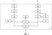
Щит 3 аварийного переключения источников переменного тока (фиг.2) содержит первый силовой ввод 22, автоматический выключатель 23 сети, устройство защитного отключения 24, реверсивный рубильник (пакетный выключатель) 25, индикатор 26 наличия сети, переключатель измерительного прибора 27, блок контроля 28 напряжения сети, второй силовой ввод 29, автоматический выключатель 30 резервной сети, коммутационный аппарат (контактор) 31, блок контроля 32 изоляции и индикатор 33 наличия резервной сети.
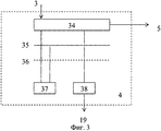
Блок 4 входной силовой шины (фиг.3) содержит трехпроводную силовую шину 34, включающую три фазных провода L1, L2 и L3, нулевой рабочий 35 провод N, нулевой защитный провод 36 (контур заземления), ограничитель перенапряжения 37 сети и однополюсный автоматический выключатель 38.The input power bus block 4 (Fig. 3) contains a three-
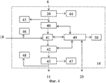
Устройство 14 бесперебойного питания (фиг.4) содержит блок 39 входных силовых цепей, блок выпрямителей 40, автоматический выключатель 41 аккумуляторных батарей, блок инверторов 42, блок 43 выходных силовых цепей, блок контроля 44 входного напряжения переменного тока, индикатор 45 наличия входного напряжения, индикатор 46 наличия напряжения аккумуляторной батареи, блок контроля 47 выходного напряжения переменного тока, индикатор 48 наличия выходного напряжения, контроллер 49 и дисплей 50.The uninterruptible power supply device 14 (Fig. 4) comprises a
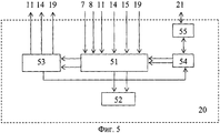
Пульт управления 20 системой электроснабжения (см. фиг.5) содержит блок приема и обработки данных 51, блок отображения 52, формирователь команд управления 53, блок 54 приема и передачи информации и линейный адаптер 55.The
Выход основного источника 1 переменного тока подключен к первому силовому входу щита аварийного переключения 3 источников переменного тока, второй силовой вход которого соединен с выходом резервного источника 2 переменного тока. Выход щита аварийного переключения 3 источников переменного тока соединен со входом блока 4 входной силовой шины, выход которого через коммутационный аппарат 5 соединен со входом блока 6 выходной силовой шины, первый выход которого через блок выпрямителей 7 подключен ко входу блока распределения нагрузки 8 постоянного тока, к первому и второму выходам которого подключены входы соответственно основных 9 и вспомогательных 10 потребителей постоянного тока.The output of the
Вход-выход блока выпрямителей 7 соединен с первым входом-выходом контроллера 11, второй вход-выход которого подключен к входу-выходу первого блока 12 аккумуляторных батарей, выход которого через автоматический выключатель 13 аккумуляторной батареи соединен со вторым входом блока распределения нагрузки 8 постоянного тока, управляющий выход контроллера 11 соединен с управляющим входом автоматического выключателя 13 аккумуляторной батареи.The input-output of the
Второй выход блока 6 выходной силовой шины через устройство 14 бесперебойного питания потребителей переменного тока соединен со входом блока распределения нагрузки 15 переменного тока, первый и второй выход которого подключен ко входам соответственно основных 16 и вспомогательных 17 потребителей переменного тока, вход-выход второго блока 18 аккумуляторных батарей соединен с первым входом-выходом устройства 14 бесперебойного питания потребителей переменного тока.The second output of the output
Второй выход блока 4 входной силовой шины соединен со входом устройства 19 пожарной сигнализации, управляющий выход которого соединен с управляющим входом коммутационного аппарата 5.The second output of the input
Третий вход-выход контроллера 11 соединен с первым входом-выходом пульта управления 20 системой электроснабжения, второй вход-выход которого соединен со вторым входом-выходом устройства 14 бесперебойного питания потребителей переменного тока.The third input-output of the
Сигнальные выходы блока выпрямителей 7, блока распределения нагрузки 8 постоянного тока и блока распределения нагрузки 15 переменного тока подключены соответственно к первому, второму и третьему сигнальным входам устройства 19 пожарной сигнализации, а информационные выходы блока выпрямителей 7, блока распределения нагрузки 8 постоянного тока, блока распределения нагрузки 15 переменного тока и устройства 19 пожарной сигнализации подключены соответственно к первому, второму, третьему и четвертому информационным входам пульта управления 20 системой электроснабжения, управляющий выход которого соединен с управляющим входом устройства 19 пожарной сигнализации, линия связи 21 подключена к третьему входу-выходу пульта управления 20 системой электроснабжения.The signal outputs of the
Выход первого силового ввода 22 щита 3 аварийного переключения через автоматический выключатель 23 сети и устройство 24 защитного отключения соединен с первым входом реверсивного рубильника 25, а выход второго силового ввода 29 щита 3 через автоматический выключатель резервной 30 сети и коммутационный аппарат 31 подключен ко второму входу реверсивного рубильника 25. Вход индикатора 26 наличия напряжения сети и первый вход переключателя 27 измерительного прибора подключены к выходу устройства 24 защитного отключения, выход переключателя 27 измерительного прибора соединен со входом блока контроля 28 напряжения сети. Выход автоматического выключателя резервной 30 сети соединен со входом блока контроля 32 изоляции, управляющий выход которого соединен с управляющим входом коммутационного аппарата 31, выход которого подключен ко второму входу переключателя 27 измерительного прибора и ко входу индикатора 33 наличия напряжения резервной сети, при этом первым и вторым силовыми входами щита аварийного переключения 3 переменного тока являются входы соответственно первого 22 и второго 29 силовых вводов, а выходом щита аварийного переключения 3 переменного тока является выход реверсивного рубильника 25.The output of the
Первый вход-выход трехпроводной силовой шины 34 блока 4 входной силовой шины соединен со входом-выходом ограничителя перенапряжения 37 сети, соединенного с нулевым рабочим 35 проводом, второй вход-выход трехпроводной шины 34 соединен с входом-выходом однополюсного автоматического выключателя 38, при этом вход и выход трехпроводной силовой шины 34 являются соответственно входом и выходом блока 4 входной силовой шины, управляющим выходом которого является выход однополюсного автоматического выключателя 38.The first input-output of the three-
Выход блока 39 входных силовых цепей устройства 14 бесперебойного питания потребителей переменного тока через блок выпрямителей 40, автоматический выключатель 41 аккумуляторных батарей и блок инверторов 42 соединен со входом блока 43 выходных силовых цепей, первый выход которого соединен со входом блока контроля 47 выходного напряжения переменного тока. Вход блока контроля 44 входного напряжения соединен со вторым выходом блока 39 входных силовых цепей, к первому выходу которого подключен вход индикатора 45 наличия входного напряжения, а вход индикатора наличия 46 напряжения аккумуляторной батареи подключен ко второму входу автоматического выключателя 41 аккумуляторных батарей. Входы-выходы блока выпрямителей 40, автоматического выключателя 41 аккумуляторных батарей и блока инверторов 42 подключены соответственно к первому, второму и третьему входам-выходам контроллера 49, выход которого соединен со входом дисплея 50. Вход индикатора 48 наличия выходного напряжения соединен со вторым выходом блока 43 выходных силовых цепей, при этом вход блока 39 входных силовых цепей является входом устройства 14 бесперебойного питания, выходом которого является второй выход блока 43 выходных силовых цепей, а входом устройства 14 бесперебойного питания является второй вход автоматического выключателя 41 аккумуляторных батарей, четвертый вход-выход контроллера 49 является входом-выходом устройства 14 бесперебойного питания.The output of the input
Первые и вторые выходы блока 51 приема и обработки данных пульта управления 20 системой электроснабжения подключены соответственно ко входам блока 52 отображения и формирователя 53 команд управления, первый управляющий выход которого соединен с управляющим входом блока 54 приема и передачи информации, выход которого соединен с первым входом блока приема и обработки данных 51. Вход-выход блока 54 приема и передачи информации соединен с первым входом-выходом линейного адаптера 55, при этом первым и вторым информационными входами пульта управления 20 системой электроснабжения являются соответственно второй и третий входы блока приема и обработки данных 51, а первым входом-выходом пульта управления 20 системой электроснабжения являются соответственно четвертый вход блока 51 приема и обработки данных и второй выход формирователя 53 команд управления, вторым входом-выходом пульта управления 20 системой электроснабжения являются соответственно пятый вход блока 51 приема и обработки данных и третий выход формирователя 53 команд управления, третьим входом-выходом пульта управления 20 системой электроснабжения является второй вход-выход линейного адаптера 55, четвертый выход формирователя 53 команд управления является управляющим выходом пульта управления 20 системой электроснабжения, третьим и четвертым информационными входами которого являются соответственно шестой и седьмой входы блока 51 приема и обработки данных.The first and second outputs of the data receiving and
Щит 3 аварийного переключения указанного выше состава предназначен для подключения основного 1 и резервного 2 внешних источников переменного тока, автоматического отключения напряжения источников при повреждении или аварии на сети, переключения с основного источника на резервный с помощью реверсивного рубильника, защиты обслуживающего персонала от поражения электрическим током и аппаратуры, размещаемой в стационарном объекте, от возгораний при повреждении или ухудшении изоляции проводов, а также от коротких замыканий.The
Для обеспечения постоянного контроля сопротивления изоляции в составе щита 3 имеется блок контроля 32 изоляции, состоящий из релейного устройства и индикаторного устройства. Релейное устройство срабатывает и замыкает свои выходные контакты при недопустимом снижении сопротивления изоляции силовых цепей. Индикаторное устройство имеет на лицевой панели три индикатора, соответствующие трем интервалам контролируемого сопротивления изоляции и позволяющие визуально оценивать его значение.To ensure constant monitoring of insulation resistance as part of the
Блок 4 входной силовой шины предназначен для передачи напряжения внешних источников переменного тока к потребителям электроэнергии.
Коммутационный аппарат 5 осуществляет отключение внешнего источника переменного тока при нарушениях тепловых режимов (перегревах) в блоках системы электроснабжения, технологической аппаратуре и возможности появления аварийной ситуации (возникновении пожара).Switching
Блок 6 выходной силовой шины предназначен для распределения внешних источников переменного тока по потребителям постоянного и переменного тока. Подобно блоку 4 входной силовой шины она содержит трехпроводную силовую шину, включающую три фазных провода L1, L2 и L3, нулевой рабочий провод N, нулевой защитный провод (контур заземления), ограничитель перенапряжения сети, определенное количество однополюсных автоматических выключателей и дополнительно двух- или трехполюсные выключатели.
Блок выпрямителей 7 предназначен для преобразования напряжения трехфазного или однофазного переменного тока в напряжение постоянного тока требуемого уровня для питания основных 9 и вспомогательных 10 потребителей. Структурные схемы и возможности различных выпрямителей приведены в известном источнике [5]. Выпрямители блока 7 предназначены для преобразования переменного трехфазного тока с линейным напряжением 380 В в напряжение постоянного тока 27 В для питания основных потребителей постоянным током. Блок 7 обеспечивает автоматическое включение при подаче на его вход с выхода блока 6 переменного тока, преобразование напряжения переменного тока в постоянное напряжение указанной выше величины, защиту от перегрузки без отключения потребителей посредством ограничителя тока непрерывного действия, выдачу непосредственно и через блок 8 по информационному выходу на блок 20 сигналов исправной и аварийной работы.The
Блок 8 распределения нагрузки потребителей постоянного тока содержит входные и выходные устройства, блоки контроля напряжения и автоматические выключатели, предназначенные для приема напряжения постоянного тока от блока 7 выпрямителей, распределения напряжения по потребителям и защиты силовых цепей от короткого замыкания. Блок 8 предназначен для приема с выхода блока выпрямителей 7 напряжения 27 В постоянного тока, распределения его и коммутации силовых цепей с помощью имеющихся в его составе коммутационных аппаратов на входы основных 9 и вспомогательных 10 потребителей. Он обеспечивает прием, коммутацию и распределение электроэнергии постоянного тока напряжением 27 В, коммутацию выходов первого блока 12 аккумуляторных батарей на нагрузку, а также автоматическое переключение входа потребителей 9 и 10 на выходы аккумуляторной батареи 12 через автоматический выключатель 13 при пропадании основного источника и обратное переключение с резервных источников на основной при восстановлении нормального питания. Блок 8 обеспечивает также защиту цепей от короткого замыкания и перегрузок, автоматический контроль наличия напряжения на входах и выходах, состояния коммутационных аппаратов, выдачу в блок 20 сигналов исправной и аварийной работы.
Блок 8 осуществляет также контроль нагрузки (величины напряжения и тока), поступающей с выхода блока выпрямителей 7, и выдачу по информационному выходу на вход пульта управления 20 данных контроля нагрузки.
В качестве основных 9 и вспомогательных 10 потребителей могут выступать аппаратура и вспомогательное оборудование радиоэлектронных комплексов, для которых обязательно требуется источник напряжения постоянного тока определенной величины с необходимым качеством.The main 9 and auxiliary 10 consumers can be equipment and auxiliary equipment of electronic complexes, which necessarily require a DC voltage source of a certain magnitude with the required quality.
Контроллер 11 предназначен для управления режимами работы блока выпрямителей 7 и блока 8 распределения нагрузки постоянного тока, измерения и отображения на экране дисплея всех рабочих параметров, контроля и индикации технического состояния, контроля емкости аккумуляторных батарей блока 12, переключения аккумуляторных батарей 12 на питание потребителей и отключения батареи при глубоком разряде, обмена данными с пультом управления 20 системой электроснабжения.The
В качестве контроллера 11 может быть использован микроконтроллер типа МК 1816, который представляет собой большую интегральную схему (БИС), имеющую в своем составе все атрибуты небольшой микро-ЭВМ: арифметическое логическое устройство, устройство управления, постоянное ЗУ программ, ОЗУ данных и интерфейсные схемы [6].As the
Устройство бесперебойного питания 14 переменного тока указанного выше состава предназначено для обеспечения бесперебойного электропитания переменным током телекоммуникационных средств связи и средств жизнеобеспечения. Основными элементами устройства являются блок 40 выпрямителей и блок 18 аккумуляторных батареей, подключенных к устройству в режиме подзаряда, блок инверторов 42 и контроллер 49, осуществляющий управление режимами работы устройства 14.The uninterruptible
При этом блок 40 выпрямителей устройства 14 обеспечивает преобразование переменного трехфазного тока с напряжением 380 В в напряжение постоянного тока 12-15 В, защиту от перегрузки без отключения сети путем оснащения его ограничителем тока непрерывного действия, разблокировку аварийных защит при снятии входного переменного напряжения, равномерную нагрузку фаз источника переменного трехфазного тока, выдачу на блок сигналов исправной и аварийной работы с индикацией на лицевой панели, автоматический контроль величины напряжения постоянного тока на выходе, выдает информацию о контролируемых параметрах в контроллер 49.In this case, the
Блок инверторов 42 устройства 14 предназначен для гарантированного питания переменным током основных 16 и вспомогательных 17 потребителей.The block of
Блок 42 предназначен для получения переменного однофазного напряжения 220 В, трехфазного напряжения 380 В из постоянного напряжения 12-15 В, поступающего с выхода блока выпрямителей 40 или с выхода блока аккумуляторных батарей 18.
Блок инверторов 42 автоматически включается при подаче на его вход постоянного напряжения. Блок 42 инверторов обеспечивает выдачу потребителям переменного однофазного напряжения 220 В, переменного трехфазного напряжения 380 В, защиту от перегрузки, разблокировку аварийных защит при снятии постоянного напряжения, защитное отключение при перегрузке по одной из фаз выходного напряжения, выдачу на контроллер 49 сигналов исправной и аварийной работы с индикацией на лицевой панели, автоматический контроль величины напряжения постоянного тока 12-15 В, величины напряжения переменного тока 220 В и асимметрии выходного напряжения.The block of
Контроллер 49 устройства 14 предназначен для управления режимами работы блока выпрямителей 40, блока инверторов 42 и блока 15 распределения нагрузки постоянного тока, измерения и отображения на экране дисплея 50 всех рабочих параметров, контроля и индикации технического состояния, контроля емкости аккумуляторных батарей блока 18, переключения аккумуляторных батарей блока 18 на питание потребителей и отключения батареи при глубоком разряде, обмена данными с пультом управления 20 системой электроснабжения. Он обеспечивает возможность регулирования выходного напряжения в широком диапазоне, контроль тока нагрузки и температуры теплоотводящих элементов, а также выдачу сигнализации о перенапряжении на выходе устройства 14 по стыкам RS-232 или RS-485.The
В качестве контроллера 49 может быть использован микроконтроллер типа МК 1816, который представляет собой большую интегральную схему (БИС), имеющую в своем составе все атрибуты небольшой микро-ЭВМ: арифметическое логическое устройство, устройство управления, постоянное ЗУ программ, ОЗУ данных и интерфейсные схемы [6], а также может быть использован контроллер из модулей семейства ЭВМ «Багет-М» [7].As the
Блок распределения 15 нагрузки переменного тока предназначен для питания основных 16 и вспомогательных 17 потребителей однофазным переменным током напряжением 220 В и трехфазным током напряжением 380 В.The
Блок 15 обеспечивает прием и распределение по потребителям электроэнергии переменного тока напряжением 380/220 В, отображение на индикаторе наличия на каждом из потребителей напряжения и тока, защиту подключаемых цепей питания от токов короткого замыкания и перегрузок. Защита отходящих линий осуществляется схемными средствами без отключения и рассчитана на номинальный ток нагрузки подключаемой линии, возможность местного включения и отключения отдельных потребителей с помощью кнопок, расположенных на блоке.
Устройство 19 пожарной сигнализации содержит пусковой пульт сигнализации, охранно-пожарный пульт, пульт дистанционного пуска, световой оповещатель, светозвуковой оповещатель, блок коммутации и контроля цепей пуска. Оно предназначено для контроля состояния одного направления с запуском систем пожаротушения и дымоудаления при срабатывании не менее двух активных или пассивных извещателей в пожарном шлейфе, а также для управления внешними звуковыми и световыми оповещателями.The
Устройство 19 осуществляет прием и регистрацию извещений посредством контроля тока, протекающего в шлейфах сигнализации к блокам системы электроснабжения. В качестве извещателей, включаемых в пожарный шлейф, могут использоваться пожарные извещатели электроконтактного типа (ИП 105, МАК-1 и т.д.), пожарные извещатели, имеющие на выходе реле и сигнальные цепи активных охранных приборов (активные пожарные извещатели типа ИП 212-2 «ДИП-2» и др.). Устройство обеспечивает непрерывный контроль состояния пожарных шлейфов по протекающему в них току, а сигнальных - по их сопротивлению.The
Пульт управления 20 системой электроснабжения содержит блок 51 приема и обработки данных, блок 52 отображения, формирователь 53 команд управления, блок 54 приема и передачи информации и линейный адаптер 55. Пульт управления может быть реализован на ЭВМ из семейства "Багет" для специализированных применений, дополнительных модулей и программного обеспечения. Он включает в себя набор стандартных модулей и позволяет устанавливать дополнительные модули для решения широкого круга задач ввода, сбора, хранения, обработки, отображения и передачи данных [7].The
Блок 51 пульта управления 20 предназначен для приема и обработки данных о техническом состоянии системы электроснабжения и ее элементов. Он включает в себя модули микропроцессора и математического акселератора, представляющие собой известные элементы из семейства модулей для системы ЭВМ «Багет» [7]. Наличие указанных данных позволит своевременно принять меры по бесперебойному электропитанию основных и вспомогательных потребителей.
Блок отображения 52 пульта управления 20 системой электроснабжения предназначен для приема данных о состоянии элементов системы электроснабжения (блока 7 выпрямителей, блока 8 распределения нагрузки постоянного тока, контроллера 11, устройства 14 бесперебойного питания, блока 15 распределения нагрузки переменного тока и устройства 19 пожарной сигнализации), отображения буквенно-цифровой информации о параметрах системы электроснабжения (величины тока, напряжения, мощности, частоты переменного тока и др.), об аварийном состоянии системы и рекомендаций оператору о действиях в аварийных ситуациях.The
Блок 54 представляет собой устройство сопряжения, которое предназначено для согласования по уровням сигналов выходных цепей с физической линией 21 и передачи данных о состоянии элементов системы электроснабжения через линейный адаптер 55 пульта управления 20 на электронную вычислительную машину внешнего пункта управления системой электроснабжения.
Линейный адаптер 55 предназначен для обмена данными по физическим линиям 21 или каналам связи с внешним пунктом управления системой электроснабжения. Он обеспечивает передачу данных о состоянии элементов системы, сигналов и команд управления на вышестоящий пункт управления.
Система характеризуется несколькими режимами работы, главными из которых являются:The system is characterized by several modes of operation, the main of which are:
1) раздельное гарантированное питание потребителей электроэнергии стационарного объекта от основного 1 или резервного 2 источников переменного тока. При этом питание основных и вспомогательных потребителей постоянного тока осуществляется напряжением постоянного тока 27 В, преобразованным из напряжения переменного тока 380/220 В с помощью блока выпрямителей 7 и первого блока 12 аккумуляторных батарей, а питание основных и вспомогательных потребителей переменного тока обеспечивается переменным током напряжением 380/220 В с помощью устройства 14 бесперебойного питания переменным током и второго блока 18 аккумуляторных батарей;1) separate guaranteed power supply to consumers of electricity of a stationary object from the main 1 or
2) гарантированное питание основных и вспомогательных потребителей электроэнергии постоянного тока от первого резервного источника постоянного тока, в качестве которого выступает первый блок 12 аккумуляторных батарей. Этот режим работы обеспечивается на время, необходимое для восстановления основного 1 или резервного 2 источников электроэнергии;2) guaranteed power supply to the main and auxiliary consumers of direct current electricity from the first standby direct current source, which is the first block of 12 batteries. This mode of operation is provided for the time necessary to restore the main 1 or
3) гарантированное питание основных и вспомогательных потребителей электроэнергии переменного тока от второго резервного источника постоянного тока, в качестве которого выступает второй блок 18 аккумуляторных батарей, и блока инверторов 42, входящего в состав устройства 14 бесперебойного питания потребителей переменного тока.3) guaranteed power supply to the main and auxiliary consumers of alternating current electric power from the second standby direct current source, which is the
Первый из названных режимов обеспечивается при наличии напряжения на первом силовом вводе щита 3 аварийного переключения источников переменного тока при условии, что отклонение напряжения основного источника 1 на вводе не выходит за допустимые пределы. При этом осуществляется раздельное питание основных 9 и вспомогательных 10 потребителей постоянным током через блок выпрямителей 7 и блок 8 распределения нагрузки постоянного тока, а первый блок 12 аккумуляторных батарей является резервным источником. В данном режиме блок 7 выпрямителей осуществляет преобразование переменного тока 380/220 В в напряжение 27 В постоянного тока, которое с выхода блока 7 через блок 8 поступает к основным 9 и вспомогательным 10 потребителям электроэнергии.The first of these modes is provided when there is voltage at the first power input of the
При пропадании или отклонении напряжения основного источника 1 на первом силовом вводе щита 3 за допустимые пределы происходит срабатывание автоматического выключателя 13 под действием сигнала, вырабатываемого контроллером 11 на основании данных, поступающих с выхода блока 7 контроля входного напряжения. Замыканием контактов выключателя 13 происходит переключение питания основных 9 и вспомогательных 10 потребителей на резервный источник - первый блок 12 аккумуляторных батарей. При восстановлении основного источника 1 переменного тока переключением контактов выключателя 13 происходит автоматический возврат питания основных 9 и вспомогательных 10 потребителей от основного источника через блок 7 выпрямителей.If the voltage of the
Питание основных 16 и вспомогательных 17 потребителей переменным током осуществляется через устройство 14 бесперебойного питания и блок 15 распределения нагрузки переменного тока, а второй блок 18 аккумуляторных батарей является резервным источником для этого режима. В данном режиме блок выпрямителей 40 устройства 14 осуществляет преобразование переменного тока напряжением 380/220 В в напряжение 12-15 В постоянного тока, которое с выхода блока 40 через автоматический выключатель 41 поступает на вход блока инверторов 42. Блок инверторов 42 осуществляет преобразование поступившего напряжения постоянного тока в напряжение переменного тока, которое с выхода блока 42 через блок 43 устройства 14 поступает на вход блока распределения 15 нагрузки переменного тока и с выхода блока 15 напряжение поступает к основным 16 и вспомогательным 17 потребителям электроэнергии.The main 16 and auxiliary 17 consumers are supplied with alternating current through an uninterruptible
При пропадании или отклонении напряжения основного источника 1 на первом силовом вводе щита 3 за допустимые пределы происходит срабатывание автоматического выключателя 41 под действием сигнала, вырабатываемого контроллером 49 на основании данных, поступающих с выхода блока 40. Замыканием контактов выключателя 41 происходит переключение питания основных 16 и вспомогательных 17 потребителей на резервный источник - второй блок 18 аккумуляторных батарей, напряжение постоянного тока которого через выключатель 41 поступает на вход блока инверторов 42. Блок 42 осуществляет преобразование напряжения постоянного тока аккумуляторных батарей в напряжение переменного тока 380/220 В, которое через блок 15 поступает к основным 16 и вспомогательным 17 потребителям. При восстановлении основного источника 1 переменного тока переключением контактов выключателя 41 происходит автоматический возврат питания основных 16 и вспомогательных 17 потребителей от основного источника через блок 40 выпрямителей устройства 14 бесперебойного питания.If the voltage of the
Питание основных и вспомогательных потребителей от резервного 2 источника переменного тока осуществляется аналогично тому, как это происходит при питании от основного 1 источника электроэнергии. Отличие заключается в том, что напряжение подается через второй силовой ввод 29 щита 3 аварийного переключения.The main and auxiliary consumers are fed from the
Второй и третий режимы работы системы являются вспомогательными и обеспечивают питание потребителей в течение определенного времени. Время работы в этих режимах определяется количеством аккумуляторных батарей в первом 12 и втором блоке 18 аккумуляторных батарей и их суммарной емкостью.The second and third modes of operation of the system are auxiliary and provide power to consumers for a certain time. The operating time in these modes is determined by the number of batteries in the first 12 and
Для реализации того или иного режима работы системы электроснабжения в ней обеспечивается сбор данных о состоянии системы и ее элементов, обработка и отображение полученных данных. На основе результатов обработки данных подготавливаются рекомендации дежурному оператору по выбору наиболее оптимального варианта схемы системы электроснабжения для каждой ситуации, существующей на данный момент времени.For the implementation of a particular mode of operation of the power supply system, it provides for the collection of data on the state of the system and its elements, processing and display of the received data. Based on the data processing results, recommendations are prepared for the duty operator on choosing the most optimal variant of the power supply system scheme for each situation that exists at a given time.
Введение устройства защитного отключения 24 и блока контроля изоляции 32 в состав щита 3 аварийного переключения, устройства 19 пожарной сигнализации, а также введение пульта управления 20 системой электроснабжения позволяет обеспечить выбор и установку оптимального с точки зрения реально существующих условий режима работы системы, автоматическое переключение каналов электроснабжения с основного на резервный при выходе из строя основного источника переменного тока и автоматический возврат на электропитание потребителей по основному каналу при его восстановлении. Все это способствует повышению времени бесперебойного электропитания потребителей и обеспечению надежности работы, защите силовых цепей от повышенного напряжения и короткого замыкания в силовых цепях. При этом обеспечивается также автоматический контроль наличия напряжения на входах и выходах силовых цепей, способствующий автоматическому изменению чередования фаз и защите от ошибочного параллельного соединения различных источников электроэнергии к одним и тем же цепям при наличии напряжения на их выходах.The introduction of the residual
Положительный эффект заключается в повышении времени бесперебойного электроснабжения потребителей в условиях недостаточно развитой инфраструктуры стационарных энергосистем, обеспечении пожаробезопасности при резких изменениях напряжения в сети и надежности работы системы.The positive effect is to increase the time of uninterrupted power supply to consumers in the context of insufficiently developed infrastructure of stationary power systems, ensuring fire safety with sharp changes in the voltage in the network and the reliability of the system.
Достоинством системы является то, что ее использование позволяет обеспечить полную пожарную безопасность за счет реализации в ней функционального контроля всех параметров системы, включая контроль температурных режимов работающих блоков и устройств системы, и возможности практически мгновенного отключения потребителей электроэнергии от внешних источников переменного тока при появлении перенапряжения и возникновении короткого замыкания в сети, а также за счет внедрения средств системы пожарной сигнализации, включая температурные датчики, датчики наличия дыма в помещении для размещения радиоэлектронных комплексов (в схеме они не показаны в целях простоты изложения материалов заявки).The advantage of the system is that its use allows to ensure complete fire safety due to the implementation of functional control of all system parameters in it, including control of temperature conditions of working units and system devices, and the possibility of almost instantaneous disconnection of electricity consumers from external AC sources when overvoltage and the occurrence of a short circuit in the network, as well as due to the implementation of the fire alarm system, including temperature sensors, smoke sensors in the room for placement of electronic complexes (they are not shown in the diagram for the sake of simplicity of presentation of application materials).
Испытания изготовленного образца предлагаемой автоматизированной системы гарантированного электроснабжения стационарного объекта показали, что в ней, по сравнению с прототипом, существенно увеличивается время непрерывной работы системы при пропадании основного и резервного источников переменного тока и улучшается электропитание потребителей электроэнергией как переменным током, так и постоянным током за счет введения устройства бесперебойного питания и резервных источников постоянного тока, что подтвердило техническую реализуемость предлагаемой системы и возможность достижения поставленной цели.Tests of the manufactured sample of the proposed automated system of guaranteed power supply to a stationary object showed that, compared with the prototype, the time of continuous operation of the system significantly increases when the main and backup sources of alternating current disappear and the power supply of consumers with electric power both alternating current and direct current improves the introduction of uninterruptible power supply and backup DC sources, which confirmed the technical implementation Bridges of the proposed system and the ability to achieve this goal.
Источники информацииInformation sources
1. SU, авторское свидетельство №207283, кл. Н02J 3/02, 1967.1. SU, copyright certificate No. 207283, cl.
2. SU, авторское свидетельство №681501, кл. Н02J 3/04, 1977.2. SU, copyright certificate No. 681501, cl.
3. SU, авторское свидетельство №843090, кл. Н02J 3/04, 1981.3. SU, copyright certificate No. 843090, cl.
4. RU, патент №2183042, кл. Н02J 3/04, 2002 (прототип).4. RU, patent No. 2183042, class.
5. Энергетическая электроника. Справочное пособие. Пер. с нем. / Под ред. В.А.Лабунцова. - М.: Энергоатомиздат, 1987.5. Energy electronics. Reference manual. Per. with him. / Ed. V.A. Labuntsova. - M .: Energoatomizdat, 1987.
6. Каган Б.М., Сташин В.В. Основы проектирования микропроцессорных устройств автоматики. - М.: Энергоатомиздат, 1987.6. Kagan B.M., Stashin V.V. Fundamentals of designing microprocessor automation devices. - M .: Energoatomizdat, 1987.
7. Семейство ЭВМ «Багет-М», КБ «Корунд-М», а/я 10.7. The family of computers "Baguette-M", KB "Corund-M", PO Box 10.
Claims (5)
Priority Applications (1)
| Application Number | Priority Date | Filing Date | Title |
|---|---|---|---|
| RU2006139807/09A RU2318281C1 (en) | 2006-11-13 | 2006-11-13 | Computerized system for no-break power supply to stationary equipment |
Applications Claiming Priority (1)
| Application Number | Priority Date | Filing Date | Title |
|---|---|---|---|
| RU2006139807/09A RU2318281C1 (en) | 2006-11-13 | 2006-11-13 | Computerized system for no-break power supply to stationary equipment |
Publications (1)
| Publication Number | Publication Date |
|---|---|
| RU2318281C1 true RU2318281C1 (en) | 2008-02-27 |
Family
ID=39279091
Family Applications (1)
| Application Number | Title | Priority Date | Filing Date |
|---|---|---|---|
| RU2006139807/09A RU2318281C1 (en) | 2006-11-13 | 2006-11-13 | Computerized system for no-break power supply to stationary equipment |
Country Status (1)
| Country | Link |
|---|---|
| RU (1) | RU2318281C1 (en) |
Cited By (3)
| Publication number | Priority date | Publication date | Assignee | Title |
|---|---|---|---|---|
| RU2690008C1 (en) * | 2014-09-04 | 2019-05-30 | Итон Корпорейшн | System and method of switching an electrical system to a backup power supply in case of power failure |
| CN112583107A (en) * | 2020-12-15 | 2021-03-30 | 广东新力宽频网络有限公司 | Power supply switching circuit and power supply switching system |
| RU2762032C1 (en) * | 2020-09-22 | 2021-12-14 | Акционерное общество "Научно-производственная фирма "СИГМА" | Autonomous power supply system of a modular structure |
-
2006
- 2006-11-13 RU RU2006139807/09A patent/RU2318281C1/en not_active IP Right Cessation
Cited By (4)
| Publication number | Priority date | Publication date | Assignee | Title |
|---|---|---|---|---|
| RU2690008C1 (en) * | 2014-09-04 | 2019-05-30 | Итон Корпорейшн | System and method of switching an electrical system to a backup power supply in case of power failure |
| RU2762032C1 (en) * | 2020-09-22 | 2021-12-14 | Акционерное общество "Научно-производственная фирма "СИГМА" | Autonomous power supply system of a modular structure |
| CN112583107A (en) * | 2020-12-15 | 2021-03-30 | 广东新力宽频网络有限公司 | Power supply switching circuit and power supply switching system |
| CN112583107B (en) * | 2020-12-15 | 2023-08-01 | 广东新力宽频网络有限公司 | Power supply switching circuit and power supply switching system |
Similar Documents
| Publication | Publication Date | Title |
|---|---|---|
| US8212405B2 (en) | Metering assembly and customer load panel for power delivery | |
| KR102145266B1 (en) | System and method for monitoring power system | |
| EP2456028A2 (en) | Management, automation and communications cabinet for an electric power distribution installation | |
| US20140265584A1 (en) | Online Surveillance System to Protect Solar Power Plants | |
| WO2017127278A1 (en) | Interconnect and metering for renewables, storage and additional loads with electronically controlled disconnect capability for increased functionality | |
| KR20120138145A (en) | Intelligent cabinet-panel having energy managing function in the smart grid environment | |
| CN106026160A (en) | Distributed photovoltaic generation anti-islanding protective device | |
| RU2318281C1 (en) | Computerized system for no-break power supply to stationary equipment | |
| KR101417940B1 (en) | Cabinet panel for prevention disaster of abnormal voltage protection and method thereof | |
| KR20120086558A (en) | Solar power generation system with monitoring and neutral line replacement | |
| RU2335055C1 (en) | Vehicle independent power supply system | |
| JPH0919066A (en) | Dispersion type power supply | |
| RU2533204C1 (en) | Modular uninterrupted direct-current power supply system for consumers | |
| JP5858236B2 (en) | Battery system | |
| RU2591057C1 (en) | Temperature-compensated system of controlled rectifier-charging modules of uninterrupted power supply to consumers with direct current | |
| CN113783285A (en) | Low-voltage comprehensive distribution box | |
| KR101473224B1 (en) | Power distribution board for preventing of black out and arc fault | |
| KR101020038B1 (en) | Motor controlling board for detecting electrical loose contact and arc | |
| KR101902169B1 (en) | Apparatus and Method for Controlling Fault Monitoring and Fault Prevention of Power Supply System | |
| RU104390U1 (en) | DC SHIELD (OPTIONS) | |
| RU2740796C1 (en) | Uninterruptable dc power supply system and method | |
| RU2318282C1 (en) | Computerized no-break power supply system | |
| CN213521411U (en) | Intelligent removing system for faults of electrified railway contact network section | |
| Chanaa et al. | Islanding Detection Method of a Photovoltaic Installation Destined to Power a RLC Load and Integrated to LV Network. | |
| JP6229971B2 (en) | Power supply device |
Legal Events
| Date | Code | Title | Description |
|---|---|---|---|
| MM4A | The patent is invalid due to non-payment of fees |
Effective date: 20111114 |