RU2317191C2 - Apparatus for providing reciprocation motion, valve unit for such apparatus and pneumatic tool with such apparatus - Google Patents
Apparatus for providing reciprocation motion, valve unit for such apparatus and pneumatic tool with such apparatus Download PDFInfo
- Publication number
- RU2317191C2 RU2317191C2 RU2004128390/02A RU2004128390A RU2317191C2 RU 2317191 C2 RU2317191 C2 RU 2317191C2 RU 2004128390/02 A RU2004128390/02 A RU 2004128390/02A RU 2004128390 A RU2004128390 A RU 2004128390A RU 2317191 C2 RU2317191 C2 RU 2317191C2
- Authority
- RU
- Russia
- Prior art keywords
- valve
- fluid
- working chamber
- channel
- possibility
- Prior art date
Links
Images
Classifications
-
- B—PERFORMING OPERATIONS; TRANSPORTING
- B25—HAND TOOLS; PORTABLE POWER-DRIVEN TOOLS; MANIPULATORS
- B25D—PERCUSSIVE TOOLS
- B25D9/00—Portable percussive tools with fluid-pressure drive, i.e. driven directly by fluids, e.g. having several percussive tool bits operated simultaneously
- B25D9/14—Control devices for the reciprocating piston
- B25D9/16—Valve arrangements therefor
- B25D9/20—Valve arrangements therefor involving a tubular-type slide valve
-
- B—PERFORMING OPERATIONS; TRANSPORTING
- B25—HAND TOOLS; PORTABLE POWER-DRIVEN TOOLS; MANIPULATORS
- B25D—PERCUSSIVE TOOLS
- B25D9/00—Portable percussive tools with fluid-pressure drive, i.e. driven directly by fluids, e.g. having several percussive tool bits operated simultaneously
- B25D9/06—Means for driving the impulse member
- B25D9/12—Means for driving the impulse member comprising a built-in liquid motor, i.e. the tool being driven by hydraulic pressure
Landscapes
- Physics & Mathematics (AREA)
- Fluid Mechanics (AREA)
- Engineering & Computer Science (AREA)
- Mechanical Engineering (AREA)
- Fluid-Pressure Circuits (AREA)
- Percussive Tools And Related Accessories (AREA)
- Lift Valve (AREA)
- Portable Nailing Machines And Staplers (AREA)
- Finish Polishing, Edge Sharpening, And Grinding By Specific Grinding Devices (AREA)
- Actuator (AREA)
- Details Of Valves (AREA)
Abstract
Description
ОБЛАСТЬ ТЕХНИКИFIELD OF TECHNOLOGY
Изобретение относится к устройству, приводимому в действие сжатой текучей средой и предназначенному для создания возвратно-поступательного движения согласно ограничительной части п.1 формулы изобретения. Кроме того, изобретение относится к клапанному блоку для вышеупомянутого устройства и к пневматическому инструменту, содержащему такое устройство.The invention relates to a device driven by a compressed fluid and designed to create a reciprocating motion according to the restrictive part of claim 1 of the claims. In addition, the invention relates to a valve block for the aforementioned device and to a pneumatic tool comprising such a device.
УРОВЕНЬ ТЕХНИКИBACKGROUND
Такое устройство описано в патенте США №5082067. Один из вариантов его выполнения включает рабочую камеру, расположенную между двумя взаимно-подвижными частями, в каждой из которых имеется канал или трубопровод для подачи или выпуска сжатой рабочей текучей среды, например сжатого воздуха. Осевое перемещение трубчатой стойки отводит клапанный затвор от его седла и таким образом открывает путь для подачи рабочей среды в рабочую камеру.Such a device is described in US patent No. 5082067. One of the options for its implementation includes a working chamber located between two mutually movable parts, each of which has a channel or conduit for supplying or discharging compressed working fluid, such as compressed air. The axial movement of the tubular strut diverts the valve shutter from its seat and thus opens the way for the supply of the working medium to the working chamber.
Повышение давления в рабочей камере приводит к перемещению подвижных частей во взаимно противоположных направлениях, при этом когда подвижные части оказываются достаточно разделены, впускной канал закрывается, а выпускной канал в стойке открывается, выпуская рабочую среду и позволяя взаимно-подвижным частям сблизиться друг с другом, после чего вышеописанная процедура повторяется. Возвратно-поступательное движение создается с использованием системы пружин или других средств, обеспечивающих возврат частей друг к другу после снятия давления.The increase in pressure in the working chamber leads to the movement of the moving parts in mutually opposite directions, while when the moving parts are sufficiently separated, the inlet channel closes and the outlet channel in the rack opens, releasing the working medium and allowing the mutually movable parts to come closer to each other, after bringing the above procedure is repeated. The reciprocating movement is created using a system of springs or other means to ensure that the parts return to each other after depressurization.
Использование вышеописанной конструкции весьма полезно в том случае, когда две подвижные части взаимно обособлены и расположены одна за другой в одном корпусе. Такая конструкция позволяет уменьшить диаметр инструмента, а это значит снизить вес инструмента, что, в свою очередь, облегчает работу с ним, снижает требования на допуски, удешевляет производство, уменьшает количество несущих поверхностей и, таким образом, снижает вибрацию. Однако вышеописанное устройство имеет слишком малую для практического использования эффективную мощность.The use of the above construction is very useful in the case when two moving parts are mutually separate and are located one after the other in the same housing. This design allows you to reduce the diameter of the tool, and this means to reduce the weight of the tool, which, in turn, facilitates the work with it, reduces tolerance requirements, reduces the cost of production, reduces the number of bearing surfaces and, thus, reduces vibration. However, the above device has an effective power that is too small for practical use.
СУЩНОСТЬ ИЗОБРЕТЕНИЯSUMMARY OF THE INVENTION
Целью настоящего изобретения является решение проблем, присущих известным техническим решениям, и предложение таких решений, которые позволят повысить эффективность работы при сохранении преимуществ, присущих известным техническим решениям.The aim of the present invention is to solve the problems inherent in known technical solutions, and to offer such solutions that will improve work efficiency while maintaining the advantages inherent in known technical solutions.
Еще одной целью настоящего изобретения является создание устройства с улучшенными габаритами, простого и дешевого в изготовлении благодаря меньшим размерам при сохранении рабочих параметров, присущих известным техническим решениям. Еще одной целью настоящего изобретения является адаптация этих усовершенствований для устройств, работающих в качестве пневматических инструментов, имеющих системы для снижения вибрации.Another objective of the present invention is to provide a device with improved dimensions, simple and cheap to manufacture due to its smaller size while maintaining the operating parameters inherent in known technical solutions. Another objective of the present invention is the adaptation of these improvements for devices operating as pneumatic tools having systems to reduce vibration.
Эти и другие цели достигнуты в настоящем изобретении согласно признакам, изложенным в п.1 формулы изобретения.These and other objectives are achieved in the present invention according to the features set forth in claim 1.
Благодаря наличию средств управления, присоединенных по меньшей мере к одному клапанному затвору, так что клапанные затворы клапанных блоков разделены в осевом направлении, и таким образом в рабочей камере вход для текучей среды расположен отдельно от ее выхода, достигается несколько преимуществ. Положение и размеры входа и выхода независимы друг от друга. Таким образом, каждый из них можно независимо оптимизировать, чтобы достичь таких параметров и характеристик потока, которые желательны для конкретного целевого приложения данного устройства.Due to the presence of controls connected to at least one valve gate, such that the valve block valves of the valve blocks are axially divided, and thus the fluid inlet is located separately from its outlet, several advantages are achieved. The position and dimensions of the input and output are independent of each other. Thus, each of them can be independently optimized in order to achieve such parameters and flow characteristics that are desirable for a particular target application of this device.
Благодаря тому, что клапанные затворы подвижны относительно подвижных частей, достигается несколько преимуществ, например самоустановка клапанного блока. Это в свою очередь делает этот блок относительно нечувствительным к допускам, что снижает производственные затраты. Согласно особенно предпочтительному варианту выполнения настоящего изобретения клапанные затворы связаны друг с другом указанными средствами управления (например, штоком) с формированием тела клапана. Это обеспечивает прекрасную самоустановку.Due to the fact that the valve gates are movable relative to the moving parts, several advantages are achieved, for example, self-installation of the valve block. This in turn makes this unit relatively insensitive to tolerances, which reduces manufacturing costs. According to a particularly preferred embodiment of the present invention, the valve gates are connected to each other by said control means (for example, a stem) to form a valve body. This provides excellent self-installation.
То, что клапанные затворы могут в процессе работы совершать ограниченное перемещение друг относительно друга, позволяет осуществить дополнительную оптимизацию рабочего цикла. Эта возможность обеспечивает дополнительное управление рабочим циклом и, таким образом, способствует улучшению работы. Например, можно продлить период, когда сжатая текучая среда находится в рабочей камере в активном состоянии до ее выпуска.The fact that the valve gates can perform limited movement relative to each other during operation allows additional optimization of the duty cycle. This feature provides additional management of the work cycle and, thus, improves performance. For example, you can extend the period when the compressed fluid is in the working chamber in the active state until it is released.
Это может быть достигнуто за счет того, что соединение между клапанными затворами выполнено гибким и упругим. Рабочий цикл можно также изменить, если сделать гибким по меньшей мере один из клапанных затворов. Гибким и упругим может быть также выполнено по меньшей мере одно из седел клапана для достижения соответствующего функционального преимущества.This can be achieved due to the fact that the connection between the valve gates is made flexible and elastic. The duty cycle can also be changed if at least one of the valve gates is flexible. At least one of the valve seats can also be flexible and resilient to achieve a corresponding functional advantage.
Кроме того, давление текучей среды может действовать как на один клапанный затвор, так и на оба клапанных затвора, создавая ситуацию, при которой затвор или затворы находятся в таком заданном положении или положениях, в которых обеспечивается выполнение желательной функции. Размещение двух подвижных частей в общем корпусе так, что они взаимно обособлены и расположены одна за другой, причем каждая часть сидит в корпусе плотно, позволяет не только изготавливать устройства меньшего диаметра, но и с меньшей поверхностью уплотнения и меньшим количеством несущих поверхностей. Это способствует снижению производственных затрат, а кроме того, положительно влияет на несколько других важных параметров и позволяет повысить мощность устройства при меньшем шуме и уровне вибрации.In addition, the fluid pressure can act on both one valve gate and both valve valves, creating a situation in which the valve or valves are in such a predetermined position or positions in which the desired function is performed. The placement of two movable parts in a common housing so that they are mutually separate and arranged one after another, each part sitting tightly in the housing, allows not only manufacturing devices of a smaller diameter, but also with a smaller sealing surface and fewer bearing surfaces. This helps to reduce production costs, and in addition, positively affects several other important parameters and allows you to increase the power of the device with less noise and vibration.
Благодаря добавлению признаков, изложенных в зависимых пунктах формулы изобретения, достигнуты и другие преимущества.By adding the features set forth in the dependent claims, other advantages have been achieved.
КРАТКОЕ ОПИСАНИЕ ЧЕРТЕЖЕЙBRIEF DESCRIPTION OF THE DRAWINGS
Ниже изобретение описано более подробно со ссылками на сопровождающие чертежи, где:Below the invention is described in more detail with reference to the accompanying drawings, where:
на фиг.1 показано осевое сечение устройства согласно настоящему изобретению в первом положении,figure 1 shows an axial section of the device according to the present invention in a first position,
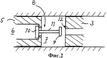
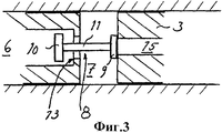
на фиг.2 и 3 показаны в укрупненном масштабе осевые сечения клапанного блока в различных положениях,figure 2 and 3 shows in an enlarged scale the axial section of the valve block in various positions,
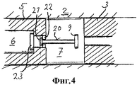
на фиг.4 показано осевое сечение второго варианта выполнения настоящего изобретения и4 shows an axial section of a second embodiment of the present invention, and
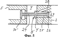
на фиг.5 показано осевое сечение третьего варианта выполнения настоящего изобретения.5 shows an axial section of a third embodiment of the present invention.
ОПИСАНИЕ ПРЕДПОЧТИТЕЛЬНЫХ ВАРИАНТОВ ВЫПОЛНЕНИЯ ИЗОБРЕТЕНИЯDESCRIPTION OF THE PREFERRED EMBODIMENTS OF THE INVENTION
В этом описании одинаковые элементы в различных вариантах выполнения настоящего изобретения могут быть обозначены одинаковыми номерами позиции.In this description, the same elements in various embodiments of the present invention can be denoted by the same reference numbers.
На фиг.1 позицией 1 обозначено устройство для создания возвратно-поступательного движения, приводимое в действие сжатой текучей средой.1, reference numeral 1 denotes a device for generating a reciprocating motion driven by a compressed fluid.
Устройство включает корпус 2, в котором размещена первая подвижная часть 5, имеющая первый канал или проход 6 для текучей среды. Кроме того, в корпусе 2 размещена вторая подвижная часть 3. Подвижная часть 3 выполнена за одно целое с частью 4, которая в данном случае является резцом, но может быть выполнена в виде напильника, ножа, пилы, зубила и т.д., или в виде поршня, ударяющего по зубилу, наковальне, игле и т.п., для осуществления некоторого воздействия на обрабатываемую заготовку (не показана). Подвижные части совместно с корпусом 2 ограничивают рабочую камеру 7.The device includes a housing 2, in which the first
Возвратно-поступательное движение, создаваемое устройством, может быть использовано и для других задач, например для приведения в действие деталей, которые должны совершать возвратно-поступательное движение. Сжатая текучая среда подается от источника сжатой текучей среды (не показан) в корпус 2 через вход 14, поступает через проход 6 для текучей среды в рабочую камеру 7 и выходит из нее по второму каналу или выпускному проходу 15 к выходу. В иллюстрируемом варианте выполнения настоящего изобретения выход выполнен в виде каналов в стенке корпуса 2. Потоком сжатой текучей среды через устройство 1 управляют с помощью клапанного блока, который включает тело 8 клапана, содержащее первый клапанный затвор 10, который взаимодействует с первой подвижной частью 5, и второй клапанный затвор 9, который взаимодействует со второй подвижной частью 3.The reciprocating movement created by the device can also be used for other tasks, for example, to actuate parts that must reciprocate. The compressed fluid is supplied from a source of compressed fluid (not shown) to the housing 2 through an inlet 14, enters through the
Более подробно это показано на фиг.2 и 3. На фиг.2 показано такое положение тела 8 клапана, при котором две указанные подвижные части находятся далеко друг от друга, а выпускной проход 15 открыт. На фиг.2 показан, в частности, первый клапанный затвор 10, который взаимодействует с поверхностью, расположенной на передней по ходу потока стороне первой части 5 и содержащей первое седло 13 клапана. Второй клапанный затвор 9 взаимодействует со вторым седлом 12 клапана, которое расположено на второй части 3 (фиг.3).This is shown in more detail in FIGS. 2 and 3. FIG. 2 shows a position of the valve body 8 in which two of the moving parts are located far from each other, and the outlet passage 15 is open. Figure 2 shows, in particular, the
Это означает, что давление текучей среды, поступающей из входа 14 сжатой текучей среды, как показано на фиг.1, прижимает первый клапанный затвор 10 к первому седлу 13 клапана в положении, показанном на фиг.2. Аналогично на второй клапанный затвор 9 давление, которое имеется в рабочей камере 7, действует в направлении второго седла 12 клапана, в результате чего проход, ведущий из рабочей камеры к выпускному проходу 15, оказывается перекрыт, как показано на фиг.3.This means that the pressure of the fluid coming from the inlet 14 of the compressed fluid, as shown in FIG. 1, presses the
На фиг.2 и 3 показано также, что тело 8 клапана включает средства управления, в данном случае шток 11, соединяющий соответственно первый и второй клапанные затворы 9 и 10. Таким образом, клапанные затворы в осевом направлении отделены друг от друга на заданное расстояние. Размеры штока 11 выбраны так, чтобы задать желательное расстояние между частями 3 и 5 и тем самым обеспечить разделение областей выхода и входа.FIGS. 2 and 3 also show that the valve body 8 includes control means, in this case a
Эта особенность настоящего изобретения обеспечивает особенно благоприятное течение потока текучей среды в рабочую камеру и из нее и позволяет избежать возмущения или ограничения соответствующего потока под влиянием элементов, относящихся к выполнению противоположной функции: входа или выхода. В иллюстрируемом варианте выполнения настоящего изобретения шток является жестким, но он может быть и гибким, как описано ниже. Конструкция с клапанными затворами и средствами управления, составляющими единый блок, который свободен в том смысле, что оба клапанных затвора подвижны относительно вышеописанных частей, является предпочтительной, поскольку обеспечивает самонастройку и делает устройство относительно нечувствительным к допускам.This feature of the present invention provides a particularly favorable flow of fluid into and out of the working chamber and avoids disturbance or restriction of the corresponding flow under the influence of elements related to performing the opposite function: inlet or outlet. In the illustrated embodiment of the present invention, the stem is rigid, but it may also be flexible, as described below. A design with valve shutters and controls constituting a single unit, which is free in the sense that both valve shutters are movable relative to the above parts, is preferable because it enables self-adjustment and makes the device relatively insensitive to tolerances.
Кроме того, на фиг.1 показано, что первая часть 5 связана с первым аккумулятором силы, в данном случае пружиной 18. При перемещении первой подвижной части в первом направлении, т.е. вперед или вправо, если смотреть на на фиг.1, на пружину 18 действует увеличивающаяся нагрузка. Ввод сжатой рабочей текучей среды в рабочую камеру 7 через впускной канал 6, минуя клапанный затвор 10, вызывает перемещение двух частей 5 и 3 в противоположных направлениях, причем если смотреть на фиг.1, первая часть 5 движется влево при одновременном уменьшении нагрузки на связанную с ней пружину, а вторая часть 3 движется вправо при одновременном увеличении нагрузки на связанный с ней аккумулятор силы, в данном случае на пружину 17. Поэтому сумма сил реакции, которые приложены двумя пружинами непосредственно или опосредованно к корпусу 2, останется по существу постоянной в течение всего цикла перемещения, что снижает колебания корпуса. Очевидно, что можно использовать и другие аккумуляторы сил, нежели пружины сжатия, например пружины растяжения, сильфоны, пневматические пружины, резиновые шланги и т.д.In addition, figure 1 shows that the
В варианте выполнения настоящего изобретения, показанном на фиг.4, клапанные затворы являются разделенными, причем второй клапанный затвор 9 имеет средства 20 управления в виде штока, в качестве направляющей которого служит первая часть, так что его перемещение относительно нее ограничено. Для этого напротив второго клапанного затвора имеется расширение 21, которое взаимодействует с удерживающими элементами в первой части 5 с тем, чтобы препятствовать выпадению средств управления из первой части 5. Средства 20 управления перемещают первый клапанный затвор 23 в открытое положение при сокращении рабочей камеры 7, т.е. когда части приближаются друг к другу, и перемещают второй клапанный затвор 9 в открытое положение при расширении рабочей камеры 7, т.е. когда части удаляются друг от друга.In the embodiment of the present invention shown in FIG. 4, the gate valves are divided, the second valve gate 9 having a rod control means 20, the first part of which serves as a guide, so that its movement relative to it is limited. For this, opposite the second valve shutter there is an extension 21 that interacts with the holding elements in the
Следует отметить, что конструкция, описанная в связи с фиг.4, может быть выполнена наоборот в том смысле, что со средствами управления может быть связан первый клапанный затвор. В этом случае в качестве направляющей средств управления служит вторая часть. При этом работа клапанных затворов осуществляется наподобие того, как описано выше.It should be noted that the design described in connection with FIG. 4 can be done in reverse in the sense that a first valve shutter may be associated with the controls. In this case, the second part serves as a guide means of control. In this case, the operation of the valve gates is carried out similar to that described above.
В варианте выполнения настоящего изобретения, показанном на фиг.5, изображена конструкция, которая в принципе работает аналогично конструкции, показанной на фиг.1-3. Однако тело 8' клапана с затворами 9' и 10' содержит трубопровод 24, который обеспечивает сообщение, т.е. возможность перемещения сжатой текучей среды между объемами (не показаны) по обе стороны частей 3 и 5. Этот вариант особенно предпочтителен при использовании текучей среды под высоким давлением для очистки продувкой, для удержания инструмента (например зубила) в определенном положении, для уменьшения силы, необходимой, чтобы открыть клапан для поступающей жидкости и т.д. В показанном варианте выполнения настоящего изобретения на теле 8' клапана имеется удлинение 25 с расширением 26 на свободном конце, причем размеры этого расширения согласованы с размерами внутренней части канала 27, а само расширение играет роль направляющей и уплотнения. Выходящая жидкость выходит через выпускной канал 28, который открывается за седлом клапанного затвора 9'. Однако удлинение 24 и расширение 26 не являются обязательными в отличие от общего принципа сообщения, т.е. возможности перемещения сжатой текучей среды через трубопровод 8'.In the embodiment of the present invention shown in FIG. 5, a structure is shown which, in principle, works similarly to the structure shown in FIGS. 1-3. However, the valve body 8 'with valves 9' and 10 'contains a
Изобретение может быть модифицировано в пределах объема формулы изобретения. Кроме того, помимо инструментов, изобретение может быть применено фактически для любого оборудования, в котором используется возвратно-поступательное движение.The invention may be modified within the scope of the claims. In addition, in addition to tools, the invention can be applied to virtually any equipment that uses reciprocating motion.
Рабочий цикл может быть изменен, если допустить по существу относительное перемещение между клапанными затворами, т.е. сделать шток 11 гибким. Рабочий цикл можно также изменить, если использовать клапанные затворы, которые обеспечивают гибкое взаимодействие между подвижными частями. Еще одним способом изменения рабочего цикла является использование гибких средств приема клапана, например седел, чтобы обеспечить гибкое взаимодействие с клапанными затворами.The duty cycle can be changed by allowing essentially relative movement between the valve gates, i.e. make
Клапанный блок может быть выполнен разнообразными способами, включая использование скользящих клапанных затворов, расположенных в соответствующих частях.The valve block can be made in a variety of ways, including the use of sliding valve gates located in their respective parts.
В качестве активной рабочей части можно использовать любую из подвижных частей, но можно также сделать так, чтобы полезную работу выполняли обе части. Например, они могут ударять по различным частям наковальни.As the active working part, you can use any of the moving parts, but you can also make sure that both parts perform useful work. For example, they can strike various parts of the anvil.
Вариант выполнения настоящего изобретения, изображенный на фиг.1, может быть модифицирован так, чтобы одна из частей была зафиксирована на опорной конструкции. В этом случае свободно перемещаться может только другая часть. Корпус может быть выполнен отдельно от любой из соответствующих частей, за одно целое с ней или жестко прикрепленным к ней.The embodiment of the present invention depicted in FIG. 1 may be modified so that one of the parts is fixed to the supporting structure. In this case, only the other part can move freely. The housing can be made separately from any of the corresponding parts, in one piece with it or rigidly attached to it.
Для возврата подвижных частей друг к другу вместо пружин сжатия может быть использовано множество других решений, включая использование сжатой текучей среды, поступающей из источника сжатой текучей среды.To return the moving parts to each other, instead of compression springs, many other solutions can be used, including the use of compressed fluid coming from a source of compressed fluid.
Claims (13)
Applications Claiming Priority (2)
| Application Number | Priority Date | Filing Date | Title |
|---|---|---|---|
| EP02445029A EP1362674B1 (en) | 2002-03-05 | 2002-03-05 | Device for generating a reciprocating movement and pneumatic tool |
| EP02445029.8 | 2002-03-05 |
Publications (2)
| Publication Number | Publication Date |
|---|---|
| RU2004128390A RU2004128390A (en) | 2005-07-20 |
| RU2317191C2 true RU2317191C2 (en) | 2008-02-20 |
Family
ID=27771999
Family Applications (1)
| Application Number | Title | Priority Date | Filing Date |
|---|---|---|---|
| RU2004128390/02A RU2317191C2 (en) | 2002-03-05 | 2003-03-01 | Apparatus for providing reciprocation motion, valve unit for such apparatus and pneumatic tool with such apparatus |
Country Status (11)
| Country | Link |
|---|---|
| US (1) | US7051995B2 (en) |
| EP (1) | EP1362674B1 (en) |
| JP (1) | JP4679821B2 (en) |
| KR (1) | KR100932031B1 (en) |
| CN (1) | CN1331639C (en) |
| AT (1) | ATE285874T1 (en) |
| CA (1) | CA2477496C (en) |
| DE (1) | DE60202445T2 (en) |
| ES (1) | ES2235003T3 (en) |
| RU (1) | RU2317191C2 (en) |
| WO (1) | WO2003074234A1 (en) |
Families Citing this family (9)
| Publication number | Priority date | Publication date | Assignee | Title |
|---|---|---|---|---|
| JP2007030527A (en) | 2005-02-17 | 2007-02-08 | Nsk Ltd | Motor-driven position adjustment apparatus for steering wheel |
| FI119398B (en) * | 2006-12-21 | 2008-10-31 | Sandvik Mining & Constr Oy | The impactor, |
| US20160249534A1 (en) * | 2007-11-09 | 2016-09-01 | Ronald Alan Gatten | Pneumatically powered pole saw |
| US8939052B2 (en) * | 2007-11-09 | 2015-01-27 | Ronald Alan Gatten | Pneumatically powered pole saw |
| WO2013158534A1 (en) * | 2012-04-16 | 2013-10-24 | Ronald Alan Gatten | Pneumatically powered pole saw |
| US9510517B2 (en) | 2007-11-09 | 2016-12-06 | Ronald Alan Gatten | Pneumatically powered pole saw |
| US10070990B2 (en) | 2011-12-08 | 2018-09-11 | Alcon Research, Ltd. | Optimized pneumatic drive lines |
| US9517161B2 (en) | 2011-12-20 | 2016-12-13 | Alcon Research, Ltd. | Vitrectomy probe with adjustable cutter port size |
| NO335354B1 (en) * | 2013-02-18 | 2014-12-01 | Pav Holding As | High frequency liquid driven drill hammer for percussion drilling in hard formations |
Family Cites Families (16)
| Publication number | Priority date | Publication date | Assignee | Title |
|---|---|---|---|---|
| US526342A (en) * | 1894-09-18 | Tenths to james wolstencroft | ||
| US1861042A (en) * | 1930-04-28 | 1932-05-31 | John A Zublin | Rotary bit with hammering device |
| US2705501A (en) * | 1953-04-09 | 1955-04-05 | Cincinnati Shaper Co | Non-repeat valve |
| US2913005A (en) * | 1956-07-23 | 1959-11-17 | Hughes Tool Co | Pilot-actuated control valve |
| SE416901C (en) * | 1979-03-30 | 1985-03-10 | Atlas Copco Ab | PNEUMATIC BATTERY MECHANISM |
| ZA814749B (en) * | 1981-07-13 | 1982-07-28 | Chamber Of Mines Services Ltd | Hydraulic reciprocating machines |
| SE443738B (en) * | 1982-09-30 | 1986-03-10 | Atlas Copco Ab | HYDRAULIC STRAPPING DRIVER OPERATED WITH SCREWS |
| SE8207351L (en) * | 1982-12-22 | 1984-06-23 | Peter Johan Torsten Tornqvist | SET AND DEVICE TO BALANCE A FRONT AND RETURN MOVEMENT |
| JPS59209775A (en) * | 1983-05-13 | 1984-11-28 | 株式会社ランドマ−クウエスト | Rock drill |
| SE444127B (en) * | 1984-06-25 | 1986-03-24 | Atlas Copco Ab | PRESSURE WASHING DRIVE SINGLE DRILLING MACHINE |
| US5108400A (en) * | 1988-01-21 | 1992-04-28 | Aesculap Ag | Striking tool for surgical instruments |
| SE460349B (en) * | 1988-02-22 | 1989-10-02 | Toernqvist Peter J T | FORMING AND MOVING MOVEMENT ALREADY APPLIANCES WITH TWO FRIENDS |
| DE3913351A1 (en) * | 1989-04-22 | 1990-10-25 | Teves Gmbh Alfred | DEVICE FOR AUXILIARY PRINTING |
| US5065824A (en) * | 1989-12-28 | 1991-11-19 | Esco Corporation | Hydraulically powered repetitive impact hammer |
| US5899232A (en) * | 1998-04-14 | 1999-05-04 | Coulter International Corp. | Debris-resistant hydropneumatic valve |
| DE29912784U1 (en) * | 1999-07-22 | 1999-09-30 | Heilmeier & Weinlein | Seat valve |
-
2002
- 2002-03-05 EP EP02445029A patent/EP1362674B1/en not_active Expired - Lifetime
- 2002-03-05 DE DE60202445T patent/DE60202445T2/en not_active Expired - Lifetime
- 2002-03-05 AT AT02445029T patent/ATE285874T1/en active
- 2002-03-05 ES ES02445029T patent/ES2235003T3/en not_active Expired - Lifetime
-
2003
- 2003-03-01 CN CNB038051869A patent/CN1331639C/en not_active Expired - Lifetime
- 2003-03-01 KR KR1020047013735A patent/KR100932031B1/en active IP Right Grant
- 2003-03-01 RU RU2004128390/02A patent/RU2317191C2/en active IP Right Revival
- 2003-03-01 US US10/506,724 patent/US7051995B2/en not_active Expired - Lifetime
- 2003-03-01 WO PCT/EP2003/002118 patent/WO2003074234A1/en active IP Right Grant
- 2003-03-01 CA CA2477496A patent/CA2477496C/en not_active Expired - Lifetime
- 2003-03-01 JP JP2003572726A patent/JP4679821B2/en not_active Expired - Lifetime
Also Published As
| Publication number | Publication date |
|---|---|
| EP1362674B1 (en) | 2004-12-29 |
| DE60202445T2 (en) | 2006-05-04 |
| US20050109521A1 (en) | 2005-05-26 |
| JP2005518950A (en) | 2005-06-30 |
| WO2003074234A1 (en) | 2003-09-12 |
| EP1362674A1 (en) | 2003-11-19 |
| JP4679821B2 (en) | 2011-05-11 |
| AU2003210394A1 (en) | 2003-09-16 |
| CA2477496A1 (en) | 2003-09-12 |
| US7051995B2 (en) | 2006-05-30 |
| CN1331639C (en) | 2007-08-15 |
| KR100932031B1 (en) | 2009-12-15 |
| CN1638923A (en) | 2005-07-13 |
| KR20040105209A (en) | 2004-12-14 |
| ES2235003T3 (en) | 2005-07-01 |
| CA2477496C (en) | 2011-09-20 |
| RU2004128390A (en) | 2005-07-20 |
| DE60202445D1 (en) | 2005-02-03 |
| ATE285874T1 (en) | 2005-01-15 |
Similar Documents
| Publication | Publication Date | Title |
|---|---|---|
| JP2905430B2 (en) | Fluid pressure cylinder | |
| RU2317191C2 (en) | Apparatus for providing reciprocation motion, valve unit for such apparatus and pneumatic tool with such apparatus | |
| TW520315B (en) | Workpiece high-speed pressurizing method and machanism by using cylinder with cushioning mechanism | |
| JP4576423B2 (en) | Animal pressure | |
| US8292003B2 (en) | Handheld tool with a linear oscillating drive | |
| CN112969859A (en) | Flow rate controller and driving device provided with same | |
| KR100354367B1 (en) | Explosive-powered pin-tapping device with hydraulic shock absorber | |
| JPH05106759A (en) | Spring driving hydraulic actuator | |
| US7392734B2 (en) | Actuator using fluid cylinder, method of controlling the actuator, and choke valve devices | |
| WO2018198535A1 (en) | Pressure booster and cylinder apparatus provided with same | |
| JP6314903B2 (en) | Flow path unit and switching valve | |
| JP4651437B2 (en) | Hydraulic cylinder | |
| US6668988B2 (en) | Buffering mechanism | |
| US20140190346A1 (en) | Economizer Device For Linear Pneumatic Actuator | |
| US8006776B1 (en) | Sliding pressure control valve for pneumatic hammer drill | |
| JPH1113707A (en) | Hydraulically switching unit | |
| AU2003210394B2 (en) | Device for generating a reciprocating movement, valve arrangement therefore and pneumatic tool | |
| FI96132B (en) | Pressure medium device and pump | |
| JP4554345B2 (en) | Booster | |
| KR20220004918A (en) | Hydraulic cylinder equipped with damper for piston | |
| SU1461910A1 (en) | Arrangement for adjusting the position of cutting member of mining machine | |
| JP6606350B2 (en) | Control pressure generator and hydraulic system | |
| KR20150122942A (en) | Hydraulic cylinder equipped with damper for piston | |
| RU2083882C1 (en) | Reciprocating pneumohydraulic drive |
Legal Events
| Date | Code | Title | Description |
|---|---|---|---|
| MM4A | The patent is invalid due to non-payment of fees |
Effective date: 20130302 |
|
| NF4A | Reinstatement of patent |
Effective date: 20131110 |