RU2316082C2 - Fuel cell assembly technique - Google Patents
Fuel cell assembly technique Download PDFInfo
- Publication number
- RU2316082C2 RU2316082C2 RU2005103229/09A RU2005103229A RU2316082C2 RU 2316082 C2 RU2316082 C2 RU 2316082C2 RU 2005103229/09 A RU2005103229/09 A RU 2005103229/09A RU 2005103229 A RU2005103229 A RU 2005103229A RU 2316082 C2 RU2316082 C2 RU 2316082C2
- Authority
- RU
- Russia
- Prior art keywords
- channels
- foil
- distribution
- plate
- fuel cell
- Prior art date
Links
Images

Classifications
-
- H—ELECTRICITY
- H01—ELECTRIC ELEMENTS
- H01M—PROCESSES OR MEANS, e.g. BATTERIES, FOR THE DIRECT CONVERSION OF CHEMICAL ENERGY INTO ELECTRICAL ENERGY
- H01M8/00—Fuel cells; Manufacture thereof
- H01M8/02—Details
- H01M8/0202—Collectors; Separators, e.g. bipolar separators; Interconnectors
- H01M8/0204—Non-porous and characterised by the material
- H01M8/0206—Metals or alloys
- H01M8/0208—Alloys
- H01M8/021—Alloys based on iron
-
- H—ELECTRICITY
- H01—ELECTRIC ELEMENTS
- H01M—PROCESSES OR MEANS, e.g. BATTERIES, FOR THE DIRECT CONVERSION OF CHEMICAL ENERGY INTO ELECTRICAL ENERGY
- H01M8/00—Fuel cells; Manufacture thereof
- H01M8/02—Details
- H01M8/0202—Collectors; Separators, e.g. bipolar separators; Interconnectors
- H01M8/0204—Non-porous and characterised by the material
- H01M8/0223—Composites
- H01M8/0228—Composites in the form of layered or coated products
-
- H—ELECTRICITY
- H01—ELECTRIC ELEMENTS
- H01M—PROCESSES OR MEANS, e.g. BATTERIES, FOR THE DIRECT CONVERSION OF CHEMICAL ENERGY INTO ELECTRICAL ENERGY
- H01M8/00—Fuel cells; Manufacture thereof
- H01M8/02—Details
- H01M8/0202—Collectors; Separators, e.g. bipolar separators; Interconnectors
- H01M8/0247—Collectors; Separators, e.g. bipolar separators; Interconnectors characterised by the form
-
- H—ELECTRICITY
- H01—ELECTRIC ELEMENTS
- H01M—PROCESSES OR MEANS, e.g. BATTERIES, FOR THE DIRECT CONVERSION OF CHEMICAL ENERGY INTO ELECTRICAL ENERGY
- H01M8/00—Fuel cells; Manufacture thereof
- H01M8/02—Details
- H01M8/0202—Collectors; Separators, e.g. bipolar separators; Interconnectors
- H01M8/0258—Collectors; Separators, e.g. bipolar separators; Interconnectors characterised by the configuration of channels, e.g. by the flow field of the reactant or coolant
- H01M8/0263—Collectors; Separators, e.g. bipolar separators; Interconnectors characterised by the configuration of channels, e.g. by the flow field of the reactant or coolant having meandering or serpentine paths
-
- H—ELECTRICITY
- H01—ELECTRIC ELEMENTS
- H01M—PROCESSES OR MEANS, e.g. BATTERIES, FOR THE DIRECT CONVERSION OF CHEMICAL ENERGY INTO ELECTRICAL ENERGY
- H01M8/00—Fuel cells; Manufacture thereof
- H01M8/02—Details
- H01M8/0202—Collectors; Separators, e.g. bipolar separators; Interconnectors
- H01M8/0267—Collectors; Separators, e.g. bipolar separators; Interconnectors having heating or cooling means, e.g. heaters or coolant flow channels
-
- H—ELECTRICITY
- H01—ELECTRIC ELEMENTS
- H01M—PROCESSES OR MEANS, e.g. BATTERIES, FOR THE DIRECT CONVERSION OF CHEMICAL ENERGY INTO ELECTRICAL ENERGY
- H01M8/00—Fuel cells; Manufacture thereof
- H01M8/04—Auxiliary arrangements, e.g. for control of pressure or for circulation of fluids
- H01M8/04082—Arrangements for control of reactant parameters, e.g. pressure or concentration
- H01M8/04089—Arrangements for control of reactant parameters, e.g. pressure or concentration of gaseous reactants
- H01M8/04119—Arrangements for control of reactant parameters, e.g. pressure or concentration of gaseous reactants with simultaneous supply or evacuation of electrolyte; Humidifying or dehumidifying
-
- H—ELECTRICITY
- H01—ELECTRIC ELEMENTS
- H01M—PROCESSES OR MEANS, e.g. BATTERIES, FOR THE DIRECT CONVERSION OF CHEMICAL ENERGY INTO ELECTRICAL ENERGY
- H01M8/00—Fuel cells; Manufacture thereof
- H01M8/24—Grouping of fuel cells, e.g. stacking of fuel cells
- H01M8/241—Grouping of fuel cells, e.g. stacking of fuel cells with solid or matrix-supported electrolytes
-
- H—ELECTRICITY
- H01—ELECTRIC ELEMENTS
- H01M—PROCESSES OR MEANS, e.g. BATTERIES, FOR THE DIRECT CONVERSION OF CHEMICAL ENERGY INTO ELECTRICAL ENERGY
- H01M8/00—Fuel cells; Manufacture thereof
- H01M8/24—Grouping of fuel cells, e.g. stacking of fuel cells
- H01M8/2465—Details of groupings of fuel cells
- H01M8/2483—Details of groupings of fuel cells characterised by internal manifolds
-
- H—ELECTRICITY
- H01—ELECTRIC ELEMENTS
- H01M—PROCESSES OR MEANS, e.g. BATTERIES, FOR THE DIRECT CONVERSION OF CHEMICAL ENERGY INTO ELECTRICAL ENERGY
- H01M8/00—Fuel cells; Manufacture thereof
- H01M8/04—Auxiliary arrangements, e.g. for control of pressure or for circulation of fluids
- H01M8/04007—Auxiliary arrangements, e.g. for control of pressure or for circulation of fluids related to heat exchange
-
- Y—GENERAL TAGGING OF NEW TECHNOLOGICAL DEVELOPMENTS; GENERAL TAGGING OF CROSS-SECTIONAL TECHNOLOGIES SPANNING OVER SEVERAL SECTIONS OF THE IPC; TECHNICAL SUBJECTS COVERED BY FORMER USPC CROSS-REFERENCE ART COLLECTIONS [XRACs] AND DIGESTS
- Y02—TECHNOLOGIES OR APPLICATIONS FOR MITIGATION OR ADAPTATION AGAINST CLIMATE CHANGE
- Y02E—REDUCTION OF GREENHOUSE GAS [GHG] EMISSIONS, RELATED TO ENERGY GENERATION, TRANSMISSION OR DISTRIBUTION
- Y02E60/00—Enabling technologies; Technologies with a potential or indirect contribution to GHG emissions mitigation
- Y02E60/30—Hydrogen technology
- Y02E60/50—Fuel cells
Abstract
Description
Область техники, к которой относится изобретениеFIELD OF THE INVENTION
Настоящее изобретение относится к топливным элементам, в частности к пластинам, распределяющим поток текучей среды, пригодным для использования в топливных элементах с твердым полимерным электролитом, пластины поля потока которых действуют как каналы подачи текучей среды к поверхностям электродов топливного элемента.The present invention relates to fuel cells, in particular to fluid distribution plates suitable for use in solid polymer electrolyte fuel cells, whose flow field plates act as channels for supplying fluid to the surfaces of the electrodes of the fuel cell.
Уровень техникиState of the art
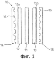
Обычные электрохимические топливные элементы преобразуют топливо и окислитель в электроэнергию и продукты реакции. Типичная схема обычного топливного элемента 10 показана на фиг.1, на которой для простоты различные слои изображены в разнесенной форме. Твердая полимерная мембрана 11 переноса ионов расположена между анодом 12 и катодом 13. Обычно анод 12 и катод 13 сформированы из электропроводного, пористого материала, такого как пористый углерод, с которым связаны небольшие частицы катализатора из платины и/или другого драгоценного металла. Анод 12 и катод 13 часто находятся в непосредственном контакте с соответствующими, расположенными рядом поверхностями мембраны 11. Эту комбинацию обычно называют мембраноэлектродной сборкой или СМЭ (МЕА).Conventional electrochemical fuel cells convert fuel and oxidizer into electricity and reaction products. A typical diagram of a
Полимерная мембрана и слои пористых электродов расположены между анодной пластиной 14 поля потока текучей среды и катодной пластиной 15 поля потока текучей среды. Между анодной пластиной 14 поля текучей среды и анодом 12 и аналогично между катодной пластиной 15 поля текучей среды и катодом 13 также могут использоваться промежуточные слои 12а и 13а подложки. Слои подложки являются пористыми по своей природе и изготовлены так, что они обеспечивают эффективную диффузию газа к поверхностям катода и анода и от них, а также помогают управлять потоками паров воды и жидкой воды. В настоящем описании считается, что при ссылке на электроды (анод и/или катод) подразумеваются электроды со слоем подложки или без него.A polymer membrane and layers of porous electrodes are disposed between the
Пластины 14, 15 поля потока текучей среды сформированы из электропроводного, непористого материала, который может находиться в электрическом контакте с соответствующим электродом 12 анода или электродом 13 катода. Одновременно пластины поля потока текучей среды должны обеспечивать подачу и/или отвод текучего топлива, окислителя и/или продукта реакции к пористым электродам или от них. Обычно это выполняется с помощью каналов для потока текучей среды, формированных на поверхности пластин поля потока текучей среды, таких как канавки или каналы 16 на поверхности, обращенной к пористым электродам 12, 13.The fluid
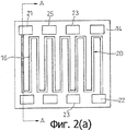
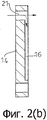
Как показано на фиг.2(а), в одной обычной конфигурации канал потока текучей среды выполнен в виде зигзагообразной структуры 20, расположенной на поверхности анода 14 (или катода 15), имеющей входной коллектор 21 и выходной коллектор 22, как показано на фиг.2(а) При этом следует понимать, что в обычной конструкции зигзагообразная структура 20 сформирована в виде канала 16 на поверхности пластины 14 (или 15), в то время как коллекторы 21 и 22 выполнены в виде отверстия, проходящего через пластину так, что текучая среда, подаваемая или отводимая от канала 20, может протекать через толщину набора пластин в направлении, ортогональном пластине, как, в частности, показано стрелкой в сечении А-А, показанном на фиг.2(b).As shown in FIG. 2 (a), in one conventional configuration, the fluid flow channel is in the form of a
Другие отверстия 23, 25 коллекторов могут быть сформированы для подачи и отвода топлива, окислителя, других текучих сред или выпускаемых продуктов в другие каналы на пластинах, не показаны.
Каналы 16 на пластинах 14, 15 поля потока текучей среды могут быть открытыми с обоих концов, то есть могут быть выполнены как каналы, проходящие между входным коллектором 21 и выпускным коллектором 22, как показано на чертеже, обеспечивая непрерывное протекание текучей среды, что обычно используется для комбинированной подачи окислителя и выпуска продуктов реакции. В качестве альтернативы, каналы 16 могут быть выполнены закрытыми на одном конце, то есть каждый канал может быть соединен только с входным коллектором 21 для подачи текучей среды, при этом его работа полностью основана на 100%-ном переносе газообразного материала в пористые электроды СМЭ и из них Закрытый канал обычно используют для подачи водородного топлива в СМЭ 11-13 с гребенчатой структурой.The
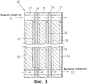
На фиг.3 показан вид в разрезе части набора пластин, из которых сформирована обычная сборка 30 топливных элементов. При такой компоновке расположенные рядом друг с другом анодные и катодные пластины поля потока текучей среды скомбинированы обычным образом для формирования одной биполярной пластины 31, имеющей каналы 32 анода на одной стороне и каналы 33 катода на противоположной стороне, причем рядом с каждой из них расположена соответствующая сборка 34 мембрана-электрод (СМЭ). Отверстия 21 входного коллектора 21 и отверстия 22 выходного коллектора наложены друг на друга так, что образуются входной и выходной коллекторы для всего набора. Различные элементы набора показаны несколько разделенными друг от друга для ясности изображения, хотя следует понимать, что они сжаты вместе с использованием, если это необходимо, уплотнительных прокладок.Figure 3 shows a sectional view of part of a set of plates from which a
Для обеспечения возможности непрерывного получения высокой мощности от топливного элемента обычно требуется поддерживать высокое содержание воды в сборке мембрана-электрод и, в частности, внутри мембраны.In order to be able to continuously obtain high power from a fuel cell, it is usually required to maintain a high water content in the membrane-electrode assembly and, in particular, inside the membrane.
В известном уровне техники это обычно достигается путем смачивания газов, топлива или воздуха, или обоих, подаваемых через коллекторы 21, 22 или 23 и каналы 16. Недостаток такой технологии состоит в том, что для поддержания достаточного уровня влажности часто требуется подогревать подаваемые на вход потоки газа и при этом необходимо использовать дополнительное устройство подачи водяного пара в протекающие потоки газа.In the prior art, this is usually achieved by wetting the gases, fuel or air, or both, supplied through the
В известном уровне техники вспомогательное устройство может быть выполнено с использованием множества разных способов. Например, используют пропускание газообразных топлива или окислителя в виде пузырьков через колонны с подогретой водой перед подачей их в топливный элемент. В качестве альтернативы применяют проницаемые мембраны, используемые в качестве среды передачи воды, при этом осуществляется перенос воды в поток газа из расположенной рядом камеры с повышенным давлением, содержащей жидкую воду. Также применяют фитили в качестве среды переноса воды в фазу жидкость - пар.In the prior art, the auxiliary device can be performed using many different methods. For example, the use of passing gaseous fuels or an oxidizing agent in the form of bubbles through columns with heated water before feeding them into the fuel cell. As an alternative, permeable membranes are used as a medium for transferring water, and water is transferred to the gas stream from a nearby high-pressure chamber containing liquid water. Wicks are also used as a medium for transferring water to the liquid - vapor phase.
Дополнительное устройство может быть установлено отдельно от набора топливного элемента или может быть сформировано как единая часть с ним. В любом случае, при его применении увеличиваются размеры и сложность сборки в целом.An additional device may be installed separately from the fuel cell kit or may be formed as a single part with it. In any case, its use increases the size and complexity of the assembly as a whole.
Альтернативный способ состоит в подаче воды непосредственно в мембрану 11, 34, например непосредственно на поверхность электрода или в каналы 16 биполярных пластин 31. Эта технология имеет преимущество, состоящее в том, что при подаче воды обеспечивается не только высокое содержание воды в мембране, но также охлаждение топливного элемента в результате испарения и отбора латентной теплоты при испарении.An alternative method is to supply water directly to the
Такой способ непосредственного отбора тепла, который обеспечивает отбор энергии вместе с выходным потоком газа, имеет явные преимущества, связанные с устранением из конструкции сборки набора топливного элемента промежуточных охлаждающих пластин.This method of direct heat extraction, which provides energy extraction together with the gas outlet stream, has obvious advantages associated with eliminating intermediate cooling plates from the fuel cell assembly design.
В известном уровне техники обычно используют режим охлаждения, при котором теплообменные пластины располагают между электрохимически активными пластинами для отбора тепловой энергии, вырабатываемой из-за резистивной и термодинамической неэффективности топливного элемента. В таких теплообменных или охлаждающих пластинах используют регулируемый поток текучей среды или, реже, поток текучей среды с однократной циркуляцией, с помощью которого отводят тепло от набора топливных элементов. Охлаждающие пластины обычно имеют другую конструкцию, чем активные пластины, что усложняет, увеличивает размеры и стоимость сборки топливных элементов.In the prior art, a cooling mode is usually used in which heat transfer plates are arranged between electrochemically active plates to select heat energy generated due to the resistive and thermodynamic inefficiency of the fuel cell. In such heat transfer or cooling plates, an adjustable fluid flow or, less commonly, a single circulation fluid flow, using which heat is removed from a set of fuel cells, is used. Cooling plates usually have a different design than active plates, which complicates, increases the size and cost of assembly of fuel cells.
Трудность, с которой можно столкнуться при непосредственной подаче воды, состоит в том, что требуется подавать точные количества воды во множество каналов 16 пластины поля потока текучей среды набора 30 топливных элементов. Обычно для этого требуется подавать точные количества воды во много тысяч отдельных мест подачи. Для выполнения этой задачи требуется использовать пластины 14, 15 или 31 поля потока текучей среды со сложной конструкцией, которые являются более трудоемкими при производстве, что приводит к повышению затрат.The difficulty that may be encountered with direct water supply is that it is necessary to supply exact amounts of water to the plurality of
Если подача воды будет неравномерной, эффект охлаждения будет плохо распределен, в результате чего образуются локализованные тепловые пятна, перегрев в которых может привести к возникновению физических напряжений и повреждению мембраны 11, ухудшению механических свойств и даже к разрывам. Такой эффект возникает как при плохой (неравномерной) подаче по поверхности пластины, так и при неравномерной подаче к каждому отдельному элементу, из которых составлен набор. Другими словами, изменения температуры могут происходить в пределах элемента или от элемента к элементу.If the water supply is uneven, the cooling effect will be poorly distributed, resulting in the formation of localized thermal spots, overheating in which can lead to physical stresses and damage to the
Сущность изобретенияSUMMARY OF THE INVENTION
Настоящее изобретение направлено на создание улучшенных способа и устройства, предназначенных для управляемой подачи воды в отдельные каналы на пластинах потока текучей среды. Кроме того, настоящее изобретение направлено на создание такого способа и устройства, которые обеспечивают простоту изготовления и сборки.The present invention is directed to the creation of an improved method and device for the controlled supply of water to individual channels on the fluid flow plates. In addition, the present invention is directed to the creation of such a method and device that provides ease of manufacture and assembly.
В соответствии с одним аспектом настоящее изобретение направлено на создание сборки топливного элемента, содержащей:In accordance with one aspect, the present invention is directed to a fuel cell assembly comprising:
пластину поля потока текучей среды, на поверхности которой сформировано множество каналов, проходящих по поверхности пластины в виде определенной структуры;a plate of a fluid flow field, on the surface of which a plurality of channels are formed, passing along the plate surface in the form of a certain structure;
фольгу распределения, на поверхности которой сформировано множество каналов, проходящих от первой кромки фольги распределения до второй кромки фольги распределения, причем эти каналы заканчиваются на второй кромке в местоположениях, по существу, совпадающих с соответствующими местоположениями каналов пластины поля;a distribution foil on the surface of which a plurality of channels are formed extending from the first edge of the distribution foil to the second edge of the distribution foil, these channels ending at the second edge at locations substantially coinciding with the corresponding locations of the channels of the field plate;
покрывающую фольгу, расположенную поверх фольги распределения так, что она покрывает каналы фольги распределения и, таким образом, формирует каналы для воды между двумя слоями фольги.a coating foil located on top of the distribution foil so that it covers the channels of the distribution foil and thus forms water channels between the two layers of the foil.
В соответствии с другим аспектом настоящее изобретение направлено на создание сборки топливного элемента, содержащей:In accordance with another aspect, the present invention is directed to a fuel cell assembly comprising:
пластину поля потока текучей среды, на поверхности которой сформировано множество каналов, проходящих по поверхности пластины в виде определенной структуры;a plate of a fluid flow field, on the surface of which a plurality of channels are formed, passing along the plate surface in the form of a certain structure;
фольгу распределения, на поверхности которой сформировано множество каналов, причем каждый из каналов продолжается от первых местоположений, расположенных рядом с или на первой кромке фольги распределения, до вторых местоположений, расположенных рядом с или на второй кромке фольги распределения, причем каналы заканчиваются во вторых местоположениях, по существу, совпадающих с соответствующими местоположениями каналов расположенной ниже пластины;a distribution foil, on the surface of which a plurality of channels are formed, each channel extending from first locations located near or on the first edge of the distribution foil to second locations located near or on the second edge of the distribution foil, the channels ending in second locations, essentially coinciding with the corresponding locations of the channels located below the plate;
покрывающую фольгу, которая имеет такие же размеры, что и существенная часть фольги распределения, которая покрывает каналы фольги распределения поверх, по меньшей мере, части их длины, между первыми и вторыми местоположениями и, таким образом, формирует каналы для воды между двумя слоями фольги.a coating foil that is the same size as a substantial portion of the distribution foil, which covers the distribution foil channels over at least a portion of their length, between the first and second locations, and thus forms water channels between the two layers of the foil.
В соответствии с еще одним аспектом настоящее изобретение направлено на создание узла топливного элемента, содержащего:In accordance with yet another aspect, the present invention is directed to a fuel cell assembly comprising:
пластину поля потока текучей среды, на поверхности которой сформировано множество каналов, проходящих по поверхности пластины поля в виде определенной структуры;a fluid flow field plate, on the surface of which a plurality of channels are formed, passing along the surface of the field plate in the form of a certain structure;
расположенную рядом мембраноэлектродную сборку (СМЭ), находящуюся в контакте с пластиной поля потока текучей среды в активной области СМЭ;an adjacent membrane electrode assembly (SME) in contact with the plate of the fluid flow field in the active SME region;
мембрану распределения, расположенную между пластиной поля потока текучей среды и СМЭ, причем мембрана содержит множество каналов для воды, проходящих через нее между первыми местоположениями, расположенными рядом с или на первой кромке мембраны, до вторых местоположений, расположенных рядом с или на второй кромке мембраны, причем каналы заканчиваются во вторых местоположениях, которые, по существу, совпадают с соответствующими местоположениями каналов пластины.a distribution membrane located between the plate of the fluid flow field and the BMS, the membrane containing many channels for water passing through it between the first locations located near or on the first edge of the membrane, to the second locations located near or on the second edge of the membrane, moreover, the channels end at second locations, which essentially coincide with the corresponding locations of the channels of the plate.
Краткое описание чертежейBrief Description of the Drawings
Варианты выполнения настоящего изобретения будут описаны ниже в качестве примера и со ссылкой на прилагаемые чертежи, на которых:Embodiments of the present invention will be described below by way of example and with reference to the accompanying drawings, in which:
на фиг.1 схематично показан вид в разрезе части обычного топливного элемента,1 schematically shows a sectional view of part of a conventional fuel cell,
на фиг.2(а) и 2(b) соответственно показан упрощенный вид в плане и вид в разрезе пластины поля потока текучей среды топливного элемента по фиг.1;FIGS. 2 (a) and 2 (b) respectively show a simplified plan view and a sectional view of a plate of a fluid flow field of a fuel cell of FIG. 1;
на фиг.3 показан вид в разрезе обычного набора топливных элементов с биполярными пластинами;figure 3 shows a sectional view of a conventional set of fuel cells with bipolar plates;
на фиг.4(а) показан вид в плане пластины поля потока текучей среды топливного элемента с зигзагообразным каналом для текучей среды, схематично представляющий расположение фольги распределения воды и покрывающей фольги в соответствии с настоящим изобретением;FIG. 4 (a) is a plan view of a plate of a fluid flow field of a fuel cell with a zigzag fluid channel schematically representing the arrangement of a water distribution foil and a coating foil in accordance with the present invention;
на фиг.4 (b) показан вид в плане пластины поля потока текучей среды топливного элемента с чередующейся гребенчатой структурой канала для текучей среды, схематично представляющий расположение фольги распределения воды и покрывающей фольги в соответствии с настоящим изобретением;4 (b) is a plan view of a plate of a fluid field of a fuel cell with an alternating comb structure of a fluid channel, schematically representing the arrangement of a water distribution foil and a coating foil in accordance with the present invention;
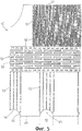
на фиг.5 показан вид в плане фольги распределения воды в соответствии с настоящим изобретением;5 shows a plan view of a foil of water distribution in accordance with the present invention;
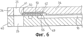
на фиг.6 показан вид в разрезе пластины поля потока текучей среды фольги распределения воды и покрывающей фольги по фиг.4 и 5;FIG. 6 is a cross-sectional view of a plate of a fluid flow field of a water distribution foil and a coating foil of FIGS. 4 and 5;
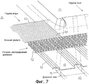
на фиг.7 показан вид в перспективе части сборки, представленной на фиг.6;Fig.7 shows a perspective view of part of the assembly shown in Fig.6;
на фиг.8 показан вид в разрезе пластины поля потока текучей среды, фольги распределения воды и покрывающей фольги, в которых используется обратное расположение фольги распределения воды и покрывающей фольги;FIG. 8 shows a sectional view of a plate of a fluid flow field, a water distribution foil, and a coating foil, in which a reverse arrangement of the water distribution foil and the coating foil is used;
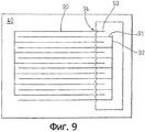
на фиг.9 схематично показан вид в плане точек впрыска воды для чередующейся гребенчатой структуры каналов.Fig. 9 schematically shows a plan view of water injection points for an alternating ridge structure of channels.
Подробное описание изобретенияDETAILED DESCRIPTION OF THE INVENTION
Как показано на фиг.4(а) и 4(b), в соответствии с настоящим изобретением предусматривается использовать последовательность каналов впрыска воды, продолжающихся между входным коллектором 25 для воды и отдельными каналами 16 пластины 40а или 40b поля потока текучей среды. Вообще говоря, каналы впрыска воды сформированы в виде мембраны или ламинированной структуры, которая расположена на поверхности пластины 40 поля потока текучей среды. Каналы впрыска воды содержат входные отверстия, соединенные с входным коллектором 25 для воды, и выходные отверстия, которые представляют собой заданные точки впрыска воды над каналами 16 пластины поля потока текучей среды.As shown in FIGS. 4 (a) and 4 (b), in accordance with the present invention, it is contemplated to use a series of water injection channels extending between the
В предпочтительном варианте компоновки ламинированная структура выполнена в виде двух слоев 41, 42 из фольги, расположенных поверх пластины 40, местоположение этих слоев фольги представлено пунктирным контуром на фиг.4(а) и 4(b).In a preferred embodiment, the laminated structure is made in the form of two
На фиг.4(а) показан вид в плане пластины 40а поля потока текучей среды с зигзагообразным каналом 16, со слоями фольги 41 а, 42а, первые кромки 43а, 44а которых совпадают с входным коллектором 25 для воды и вторые кромки 45а, 46а которых расположены на или рядом с заданными точками 49 впрыска воды каналов 16.FIG. 4 (a) shows a plan view of a plate 40a of a fluid flow field with a
На фиг.4 (b) представлен вид в плане пластины 40b поля потока текучей среды с двумя чередующимися гребенчатыми каналами 47, 48, каждый из которых соединен с соответствующим коллектором 21, 22, и слоями 41b, 42b фольги, первые кромки 43b, 44b которых совпадают с входным коллектором 25 для воды и вторые кромки 45b, 46b которых расположены на или рядом с заданными точками впрыска воды канала 47. Следует отметить, что такая фольга может быть установлена на противоположной кромке пластины 40b между вторым входным коллектором 25 для воды и заданными точками впрыска воды канала 48.Fig. 4 (b) is a plan view of a fluid flow field plate 40b with two alternating
На фиг.5, на виде в плане, подробно показано расположение фольги 41 распределения воды, где представлены предпочтительные каналы 50 для впрыска воды. Каналы 50 сформированы в виде первой последовательности каналов 51, которые продолжаются от первой кромки 43 фольги 41, расположенной на входном коллекторе 25 для воды, до галереи или камеры 52 распределения давления, которая продолжается вдоль длины фольги 41 впрыска воды. Галерея 52 распределения давления сообщается со второй последовательностью каналов 53, которые продолжаются до второй кромки 45 фольги, где они соединяются с каналами 16 на пластине поля потока текучей среды. С этой целью вторая последовательность каналов 53 сгруппирована так, что они заканчиваются на второй кромке 45 фольги 41 впрыска воды в виде соответствующих сходящихся структур 54.Figure 5, in plan view, shows in detail the location of the
В представленном предпочтительном варианте выполнения сходящиеся структуры 54 содержат дугообразные выемки 55, вырезанные на второй кромке 45 фольги 41, в точках 49 впрыска воды, выполненные так, что они совпадают с заданными местоположениями над каналами 16, показанными на чертеже схематично.In the presently preferred embodiment, the converging
Галерея 52 распределения давления предпочтительно содержит матрицу взаимосообщающихся каналов 56, которые направляют поступающую воду от первой последовательности каналов 51 и эффективно распределяют ее по всей длине фольги 41 так, что вода поступает в каждую группу второй последовательности каналов 53 под, по существу, одинаковым давлением.The
Как снова показано на фиг.4(а) и 4(b), покрывающая фольга 42 представляет собой слой фольги без какой-либо структуры (то есть без каналов), по существу, с той же формой внешнего контура, как у нижней фольги. Покрывающая фольга 42 продолжается за пределы кромки фольги 41 распределения, по меньшей мере, на концах второй последовательности каналов, что обеспечивает направление воды вниз в требуемый канал 16 пластины поля потока. Удобнее всего такое перекрытие обеспечивается благодаря тому, что в фольге 41 распределения сформированы выемки 55, а в покрывающей фольге 42 такие выемки отсутствуют. Таким образом, как лучше всего видно на схеме, в увеличенном виде показанной в разрезе на фиг.6, покрывающая фольга 46 образует верхнее покрытие для каналов 51, 52 и 53, формируя каналы 50 для впрыска воды и оставляя открытыми концы каналов 51 и 53. В представленном варианте выполнения покрывающая фольга 42 может быть сформирована с несколько большими размерами, чем фольга 41 распределения, так, что она перекрывает вторую кромку 45 (и, возможно, первую кромку 43) для получения аналогичного эффекта.As again shown in FIGS. 4 (a) and 4 (b), the
Следует отметить, что слои фольги выполнены очень тонкими по сравнению с толщиной пластины 40, при этом благодаря небольшой толщине слоев фольги они легко укладываются в СМЭ 34 при установке прокладок между пластинами. Компоненты на фиг.6 показаны несколько разделенными для ясности представления, хотя они, конечно, будут сжаты вместе.It should be noted that the layers of the foil are made very thin compared to the thickness of the
На фиг.7 показана представленная в перспективе схема фольги 41 распределения воды в местоположении поверх пластины 40 поля потока, на которой показано совмещение различных каналов и коллекторов.Fig. 7 shows a perspective diagram of a
Можно видеть, что каналы 51, 52, 53 распределения воды не обязательно должны быть сформированы на нижней фольге 41. В другом варианте выполнения, показанном на фиг.8, каналы 80 распределения воды сформированы на нижней поверхности верхней фольги 82, в то время как нижняя фольга 81 используется для формирования покрытия каналов 80 для образования каналов впрыска воды. Другими словами, фольга 82 распределения и покрывающая фольга 81 выполнены в виде перевернутой структуры по сравнению с компоновкой, представленной на фиг.6It can be seen that
В компоновке, показанной на фиг.8, по меньшей мере, вторая последовательность каналов (сравни с каналами 53 на фиг.5) не доходит непосредственно до второй кромки 83 верхней фольги, но заканчивается в местоположениях рядом со второй кромкой. Нижняя фольга 81 (покрывающая фольга) продолжается практически до конца каналов 80, но предпочтительно заканчивается на небольшом расстоянии от них, что обеспечивает сообщение по текучей среде между концом канала 80 и каналом 16 пластины в точках 49 впрыска воды,In the arrangement shown in FIG. 8, at least a second sequence of channels (compare with
Как указано выше, нижняя фольга 81 (покрывающая фольга) образует покрытие для каналов 80, формируя барьер, предотвращающий утечку воды в ненужных местах в расположенные ниже каналы 16 в пластине 40 потока текучей среды, например в местах, где каналы впрыска воды пересекают каналы 16 для топлива и/или окислителя (например, в местах 85).As indicated above, the lower foil 81 (coating foil) forms a coating for the
Предпочтительно фольга, как описано выше, сформирована из металла, такого как нержавеющая сталь. Однако можно использовать любой подходящий материал, обладающий соответствующими свойствами, обеспечивающими содержание воды под давлением, и выражение "фольга", используемое в настоящем описании, следует толковать соответственно. Предпочтительно фольга является электропроводной, но не обязательно, поскольку она не продолжается до активной области СМЭ.Preferably, the foil, as described above, is formed from a metal, such as stainless steel. However, any suitable material may be used that has the appropriate properties to provide a water content under pressure, and the expression “foil” used in the present description should be interpreted accordingly. Preferably, the foil is electrically conductive, but not necessary, since it does not extend to the active region of the MEA.
В предпочтительном варианте выполнения каналы 16 потока текучей среды на пластинах 40 анода или катода обычно имеют ширину и глубину от 0,4 мм до 1,2 мм. Было определено, что необходимая степень впрыска воды обеспечивается при значениях ширины и глубины канала, химически вытравленного в фольге распределения воды, равных 10 мкм.In a preferred embodiment, the
При использовании устройства давлением воды, подаваемой через коллектор 25, управляют для получения достаточного перепада между давлением подачи воды и давлением газа в каналах 16 потока текучей среды, что обеспечивает равномерное распределение воды между тысячами каналов потока. В предпочтительном варианте выполнения воду подают в коллектор под давлением в диапазоне 0,5-3 бар Н2О.When using the device, the water pressure supplied through the manifold 25 is controlled to obtain a sufficient difference between the water supply pressure and the gas pressure in the
Преимущество такого подхода состоит в том, что мембрана распределения воды выполнена чрезвычайно тонкой и может быть легко расположена в доступном пространстве в биполярных пластинах или в области прокладки.An advantage of this approach is that the water distribution membrane is extremely thin and can easily be located in an accessible space in bipolar plates or in the gasket area.
Точностью объемной подачи воды также можно очень точно управлять благодаря использованию соответствующей конструкции канала впрыска воды и регулируя его размеры.The accuracy of the volumetric water supply can also be very precisely controlled by using the appropriate design of the water injection channel and adjusting its size.
Воду можно подавать как на стороне потока топлива (анода), так и на стороне окислителя (катода) биполярной пластины 34 или с обеих сторон. Предпочтительно впрыск воды выполняют на стороне катода.Water can be supplied both on the side of the fuel flow (anode) and on the oxidizing side (cathode) of the
Как показано на фиг.9, воду, которую подают в чередующиеся гребенчатые каналы 90 на пластине 40 поля потока, можно подавать либо в точке 91 входа в канал, после канала 92 подачи, или в качестве альтернативы, в выходную дорожку 93, в точке 94 впрыска, расположенную на том же краю биполярной пластины, что и коллектор подачи.As shown in FIG. 9, water that is supplied to alternating
Преимущество впрыска воды в выходные дорожки состоит в уменьшении перепада давления в потоке газообразных продуктов реакции. Это происходит из-за того, что при этом вода не проходит через диффузионную среду, маскирующую пустое пространство для прохода газа. Аналогично, благодаря устранению потока воды через диффузионную среду снижается трение среды и ее постепенное разрушение и структурный износ.The advantage of injecting water into the exit paths is to reduce the pressure drop in the gaseous reaction product stream. This is due to the fact that the water does not pass through a diffusion medium masking the empty space for gas passage. Similarly, by eliminating the flow of water through the diffusion medium, the friction of the medium and its gradual destruction and structural wear are reduced.
В выходных дорожках происходит эффективное охлаждение в результате испарения, при этом в мембране поддерживается требуемое содержание воды благодаря насыщению воздуха парами воды.Effective cooling by evaporation takes place in the exit paths, while the required water content is maintained in the membrane due to the saturation of the air with water vapor.
Хотя варианты выполнения настоящего изобретения были описаны в контексте впрыска воды в топливный элемент мембраны с протонным обменом, следует понимать, что такую же структуру можно использовать для впрыска любого материала текучей среды в точках впрыска на пластине поля.Although embodiments of the present invention have been described in the context of injecting water into a proton exchange membrane fuel cell, it should be understood that the same structure can be used to inject any fluid material at the injection points on the field plate.
Другие варианты выполнения находятся в пределах прилагаемой формулы изобретения.Other embodiments are within the scope of the appended claims.
Claims (20)
Applications Claiming Priority (2)
| Application Number | Priority Date | Filing Date | Title |
|---|---|---|---|
| GB0215790A GB2390738B (en) | 2002-07-09 | 2002-07-09 | Fuel cell direct water injection |
| GB0215790.7 | 2002-07-09 |
Publications (2)
| Publication Number | Publication Date |
|---|---|
| RU2005103229A RU2005103229A (en) | 2005-07-10 |
| RU2316082C2 true RU2316082C2 (en) | 2008-01-27 |
Family
ID=9940050
Family Applications (1)
| Application Number | Title | Priority Date | Filing Date |
|---|---|---|---|
| RU2005103229/09A RU2316082C2 (en) | 2002-07-09 | 2003-07-09 | Fuel cell assembly technique |
Country Status (14)
| Country | Link |
|---|---|
| US (1) | US8614030B2 (en) |
| EP (1) | EP1530813B1 (en) |
| JP (1) | JP4936663B2 (en) |
| CN (1) | CN100435393C (en) |
| AU (1) | AU2003250398A1 (en) |
| BR (1) | BR0305419B1 (en) |
| CA (1) | CA2492109C (en) |
| ES (1) | ES2394956T3 (en) |
| GB (1) | GB2390738B (en) |
| MX (1) | MXPA05000500A (en) |
| NO (1) | NO335352B1 (en) |
| RU (1) | RU2316082C2 (en) |
| WO (1) | WO2004006367A2 (en) |
| ZA (1) | ZA200500297B (en) |
Families Citing this family (16)
| Publication number | Priority date | Publication date | Assignee | Title |
|---|---|---|---|---|
| GB2382455B (en) * | 2001-11-07 | 2004-10-13 | Intelligent Energy Ltd | Fuel cell fluid flow field plates |
| GB2412784B (en) * | 2002-01-18 | 2006-08-23 | Intelligent Energy Ltd | Fuel cell oxygen removal and pre-conditioning system |
| GB2390738B (en) | 2002-07-09 | 2005-05-11 | Intelligent Energy Ltd | Fuel cell direct water injection |
| GB2401986B (en) * | 2003-05-17 | 2005-11-09 | Intelligent Energy Ltd | Improvements in fuel utilisation in electrochemical fuel cells |
| GB2409763B (en) | 2003-12-31 | 2007-01-17 | Intelligent Energy Ltd | Water management in fuel cells |
| GB2413002B (en) * | 2004-04-08 | 2006-12-06 | Intelligent Energy Ltd | Fuel cell gas distribution |
| GB2434845B (en) * | 2006-02-01 | 2010-10-13 | Intelligent Energy Ltd | Variable compressibility gaskets |
| GB2437767B (en) | 2006-05-05 | 2010-11-17 | Intelligent Energy Ltd | Fuel cell fluid distribution plates |
| US9824008B2 (en) * | 2008-11-21 | 2017-11-21 | International Business Machines Corporation | Cache memory sharing in a multi-core processor (MCP) |
| CN103988340B (en) * | 2011-12-20 | 2017-02-15 | 联合工艺公司 | Flow battery with mixed flow |
| GB201204736D0 (en) * | 2012-03-19 | 2012-05-02 | Intelligent Energy Ltd | Fuel cell fluid distribution |
| DE102014206335A1 (en) * | 2014-04-02 | 2015-10-08 | Volkswagen Ag | Bipolar plate and fuel cell with such a |
| GB2528036A (en) * | 2014-06-30 | 2016-01-13 | Intelligent Energy Ltd | Fuel cell |
| JP2017525102A (en) | 2014-07-03 | 2017-08-31 | カウンシル オブ サイエンティフィック アンド インダストリアル リサーチ | Internal humidification in low temperature PEM fuel cells using wicks |
| US11056698B2 (en) | 2018-08-02 | 2021-07-06 | Raytheon Technologies Corporation | Redox flow battery with electrolyte balancing and compatibility enabling features |
| US11271226B1 (en) | 2020-12-11 | 2022-03-08 | Raytheon Technologies Corporation | Redox flow battery with improved efficiency |
Family Cites Families (18)
| Publication number | Priority date | Publication date | Assignee | Title |
|---|---|---|---|---|
| US5998054A (en) * | 1997-07-23 | 1999-12-07 | Plug Power, L.L.C. | Fuel cell membrane hydration and fluid metering |
| US6066408A (en) * | 1997-08-07 | 2000-05-23 | Plug Power Inc. | Fuel cell cooler-humidifier plate |
| WO2000054350A1 (en) * | 1999-03-12 | 2000-09-14 | International Fuel Cells, Llc | Water management system for fuel cell |
| US6303245B1 (en) * | 1999-08-27 | 2001-10-16 | Plug Power Inc. | Fuel cell channeled distribution of hydration water |
| JP4439076B2 (en) * | 2000-03-31 | 2010-03-24 | 株式会社東芝 | Polymer electrolyte fuel cell stack |
| SE518621C2 (en) * | 2000-07-07 | 2002-10-29 | Volvo Ab | Structure of a polymer fuel cell |
| US6566004B1 (en) * | 2000-08-31 | 2003-05-20 | General Motors Corporation | Fuel cell with variable porosity gas distribution layers |
| GB2382455B (en) | 2001-11-07 | 2004-10-13 | Intelligent Energy Ltd | Fuel cell fluid flow field plates |
| GB2412784B (en) | 2002-01-18 | 2006-08-23 | Intelligent Energy Ltd | Fuel cell oxygen removal and pre-conditioning system |
| GB2387959C (en) | 2002-03-28 | 2005-02-09 | Intelligent Energy Ltd | Fuel cell compression assembly |
| GB2390738B (en) | 2002-07-09 | 2005-05-11 | Intelligent Energy Ltd | Fuel cell direct water injection |
| GB2396688B (en) | 2002-11-22 | 2006-06-28 | Intelligent Energy Ltd | Thermal energy management in electrochemical fuel cells |
| GB2401986B (en) | 2003-05-17 | 2005-11-09 | Intelligent Energy Ltd | Improvements in fuel utilisation in electrochemical fuel cells |
| GB2409763B (en) | 2003-12-31 | 2007-01-17 | Intelligent Energy Ltd | Water management in fuel cells |
| GB2413002B (en) | 2004-04-08 | 2006-12-06 | Intelligent Energy Ltd | Fuel cell gas distribution |
| GB2422716B (en) | 2005-01-26 | 2007-08-22 | Intelligent Energy Ltd | Multi-layer fuel cell diffuser |
| GB2422717B (en) | 2005-02-01 | 2007-11-14 | Intelligent Energy Ltd | Detachable fuel cell power unit for vehicle applications |
| GB2434845B (en) | 2006-02-01 | 2010-10-13 | Intelligent Energy Ltd | Variable compressibility gaskets |
-
2002
- 2002-07-09 GB GB0215790A patent/GB2390738B/en not_active Expired - Fee Related
-
2003
- 2003-07-09 CN CNB038213419A patent/CN100435393C/en not_active Expired - Lifetime
- 2003-07-09 BR BRPI0305419-5A patent/BR0305419B1/en not_active IP Right Cessation
- 2003-07-09 AU AU2003250398A patent/AU2003250398A1/en not_active Abandoned
- 2003-07-09 CA CA2492109A patent/CA2492109C/en not_active Expired - Fee Related
- 2003-07-09 JP JP2004519011A patent/JP4936663B2/en not_active Expired - Fee Related
- 2003-07-09 WO PCT/GB2003/002973 patent/WO2004006367A2/en active Application Filing
- 2003-07-09 US US10/520,579 patent/US8614030B2/en active Active
- 2003-07-09 EP EP03762819A patent/EP1530813B1/en not_active Expired - Lifetime
- 2003-07-09 ES ES03762819T patent/ES2394956T3/en not_active Expired - Lifetime
- 2003-07-09 MX MXPA05000500A patent/MXPA05000500A/en active IP Right Grant
- 2003-07-09 RU RU2005103229/09A patent/RU2316082C2/en not_active IP Right Cessation
-
2004
- 2004-02-24 NO NO20040808A patent/NO335352B1/en not_active IP Right Cessation
-
2005
- 2005-01-12 ZA ZA200500297A patent/ZA200500297B/en unknown
Also Published As
| Publication number | Publication date |
|---|---|
| AU2003250398A8 (en) | 2004-01-23 |
| WO2004006367A2 (en) | 2004-01-15 |
| GB2390738A (en) | 2004-01-14 |
| WO2004006367A3 (en) | 2005-03-03 |
| CN1682397A (en) | 2005-10-12 |
| NO335352B1 (en) | 2014-11-24 |
| GB0215790D0 (en) | 2002-08-14 |
| BR0305419B1 (en) | 2012-12-25 |
| ES2394956T3 (en) | 2013-02-07 |
| BR0305419A (en) | 2004-10-05 |
| GB2390738B (en) | 2005-05-11 |
| EP1530813B1 (en) | 2012-05-30 |
| JP4936663B2 (en) | 2012-05-23 |
| ZA200500297B (en) | 2006-04-26 |
| EP1530813A2 (en) | 2005-05-18 |
| AU2003250398A1 (en) | 2004-01-23 |
| MXPA05000500A (en) | 2005-04-19 |
| CA2492109A1 (en) | 2004-01-15 |
| JP2005532663A (en) | 2005-10-27 |
| NO20040808L (en) | 2004-02-24 |
| RU2005103229A (en) | 2005-07-10 |
| CN100435393C (en) | 2008-11-19 |
| US8614030B2 (en) | 2013-12-24 |
| CA2492109C (en) | 2011-08-16 |
| US20060154130A1 (en) | 2006-07-13 |
Similar Documents
| Publication | Publication Date | Title |
|---|---|---|
| RU2316082C2 (en) | Fuel cell assembly technique | |
| RU2419921C2 (en) | Plates for distribution of fluid medium flows in fuel cells | |
| RU2351041C2 (en) | Gas distribution in fuel cells | |
| US8609288B2 (en) | Water management in fuel cells | |
| US6207310B1 (en) | Fuel cell with metal screen flow-field | |
| US8029942B2 (en) | Fuel cell system with flow field capable of removing liquid water from the high-pressure channels | |
| RU2507643C2 (en) | Interconnector for fuel elements and method for production of interconnector for fuel elements | |
| JP2005509260A (en) | Fuel cell flow field plate | |
| EP1952471B1 (en) | Pem fuel cell with charging chamber | |
| WO2006085172A2 (en) | Fuel cell separator | |
| US20110008703A1 (en) | Fuel cell with dead-end anode | |
| JP2019179759A (en) | Cell group for power adaptation of electrochemical reactor | |
| KR20050034647A (en) | Fuel cell with evaporative cooling and humidification |
Legal Events
| Date | Code | Title | Description |
|---|---|---|---|
| MM4A | The patent is invalid due to non-payment of fees |
Effective date: 20160710 |