RU2315373C1 - Core of high-temperature thermal reactor using finely dispersed solid coolant - Google Patents
Core of high-temperature thermal reactor using finely dispersed solid coolant Download PDFInfo
- Publication number
- RU2315373C1 RU2315373C1 RU2006124615/06A RU2006124615A RU2315373C1 RU 2315373 C1 RU2315373 C1 RU 2315373C1 RU 2006124615/06 A RU2006124615/06 A RU 2006124615/06A RU 2006124615 A RU2006124615 A RU 2006124615A RU 2315373 C1 RU2315373 C1 RU 2315373C1
- Authority
- RU
- Russia
- Prior art keywords
- fuel
- coolant
- fairings
- assemblies
- graphite
- Prior art date
Links
Images
Classifications
-
- Y—GENERAL TAGGING OF NEW TECHNOLOGICAL DEVELOPMENTS; GENERAL TAGGING OF CROSS-SECTIONAL TECHNOLOGIES SPANNING OVER SEVERAL SECTIONS OF THE IPC; TECHNICAL SUBJECTS COVERED BY FORMER USPC CROSS-REFERENCE ART COLLECTIONS [XRACs] AND DIGESTS
- Y02—TECHNOLOGIES OR APPLICATIONS FOR MITIGATION OR ADAPTATION AGAINST CLIMATE CHANGE
- Y02E—REDUCTION OF GREENHOUSE GAS [GHG] EMISSIONS, RELATED TO ENERGY GENERATION, TRANSMISSION OR DISTRIBUTION
- Y02E30/00—Energy generation of nuclear origin
- Y02E30/30—Nuclear fission reactors
Landscapes
- Monitoring And Testing Of Nuclear Reactors (AREA)
Abstract
Description
1. Область техники, к которой относится изобретение.1. The technical field to which the invention relates.
Изобретение относится к области ядерной энергетики, в частности к активным зонам высокотемпературных ядерных реакторов на тепловых нейтронах с твердым мелкодисперсным теплоносителем.The invention relates to the field of nuclear energy, in particular to the active zones of high-temperature thermal neutron reactors with solid finely divided coolant.
2. Уровень техники2. The level of technology
Известна активная зона высокотемпературного ядерного реактора на тепловых нейтронах с твердым мелкодисперсным теплоносителем, состоящая из тепловыделяющих сборок, собранных из вертикально расположенных твэлов с помощью дистанционирующих деталей, формирующих зазоры для прохода графитосодержащего теплоносителя и опирающихся на корпус реактора через переходные детали с возможностью частичного подъема и опускания тепловыделяющих сборок из теплоносителя для регулирования реактивности (см., Rigg S., Greenlees F.M. Nuclear reactor. Патент Великобритании №1309883, МКИ G21D 5/00, НКИ G6С30Х363. Заявл. 18.02.1971, опубл. 14.03.1973]. В такой конструкции твэлы по высоте занимают практически всю активную зону, теплоноситель склонен к слипанию, что имеет следствием неравномерность теплосъема по высоте твэлов и увеличивает вероятность их термического разрушения, особенно при извлечении твэлов выше уровня теплоносителя для регулирования реактивности.The active zone of a high-temperature thermal neutron reactor with a solid finely dispersed heat carrier is known, consisting of fuel assemblies assembled from vertically arranged fuel rods using spacer parts that form gaps for the passage of a graphite-containing coolant and lean on the reactor vessel through transition parts with the possibility of partial lifting coolant assemblies for reactivity control (see, Rigg S., Greenlees FM Nuclear reactor. UK patent and No. 1309883, MKI G21D 5/00, NCI G6C30X363, Declared February 18, 1971, published March 14, 1973]. In this design, fuel rods in height occupy almost the entire active zone, the heat carrier is prone to sticking, which results in uneven heat removal in height fuel rods and increases the likelihood of their thermal destruction, especially when removing fuel rods above the coolant level to regulate reactivity.
Эта конструкция совпадает с заявляемой активной зоной по следующим существенным признакам:This design coincides with the claimed core according to the following essential features:
- имеется система управления реактивностью (путем частичного извлечения твэл из теплоносителя);- there is a reactivity control system (by partial extraction of fuel elements from the coolant);
- тепловыделяющие сборки собраны из вертикально расположенных твэлов с помощью дистанционирующих деталей, формирующих зазоры для прохода графитосодержащего теплоносителя.- fuel assemblies are assembled from vertically arranged fuel rods with the help of spacer parts, forming gaps for the passage of graphite-containing coolant.
Известна также конструкция активной зоны высокотемпературного ядерного реактора на тепловых нейтронах с мелкодисперсным твердым теплоносителем, состоящая из нижней опорной платформы с боковым отражателем нейтронов, тепловыделяющих сборок, размещенных между трубами системы управления и защиты реактора и собранных из вертикально расположенных пластинчатых твэлов с графитовой оболочкой с помощью дистанционирующих деталей, формирующих зазоры для прохода графитосодержащего теплоносителя, в которых установлены турбулизирующие элементы, выполненные в виде одностороннего оребрения, спирального оребрения или шнеков. Теплонесущие элементы выполнены из графитовой массы с покрытием из пиролитического углерода с ограничением по диаметру и несферичности, что исключает слипание (см., например, Ядерный энергетический реактор. Патент РФ №2166806, МПК G21C 15/24, от 09.02.2000 г.). Такая конструкция активной зоны также связана с существенными локальными неоднородностями теплосъема по длине твэла вследствие образования в гравитационно движущемся слое теплоносителя пустот под турбулизаторами и зон неподвижных частиц над ними.Also known is the design of the core of a high-temperature thermal neutron reactor with a finely dispersed solid coolant, consisting of a lower support platform with a lateral neutron reflector, fuel assemblies placed between the pipes of the reactor control and protection system and assembled from vertically arranged plate fuel elements with a graphite sheath using distance parts forming the gaps for the passage of graphite-containing coolant, in which turbulent elements are installed you made in the form of one-sided fins, spiral fins or screws. The heat-carrying elements are made of graphite mass coated with pyrolytic carbon with a restriction in diameter and non-sphericity, which eliminates sticking (see, for example, Nuclear Power Reactor. RF Patent No. 2166806, IPC G21C 15/24, dated 09.02.2000). This design of the active zone is also associated with significant local inhomogeneities of heat removal along the length of the fuel rod due to the formation of voids under the turbulators and zones of stationary particles above them in the gravitationally moving coolant layer.
Эта конструкция совпадает с заявляемой активной зоной по следующим существенным признакам:This design coincides with the claimed core according to the following essential features:
- нижняя опорная платформа- lower support platform
- боковой отражатель нейтронов;- lateral neutron reflector;
- трубы стержней системы управления и защиты реактора;- pipes of rods of the reactor control and protection system;
- тепловыделяющие сборки, размещенные между трубами;- fuel assemblies placed between the pipes;
- тепловыделяющие сборки собраны из вертикально расположенных твэлов с графитовой оболочкой с помощью дистанционирующих деталей, формирующих зазоры для прохода графитосодержащего теплоносителя;- fuel assemblies are assembled from vertically arranged fuel rods with a graphite cladding using spacers that form gaps for the passage of a graphite-containing coolant;
- турбулизирующие элементы, установленные в зазорах.- turbulizing elements installed in the gaps.
Последняя конструкция наиболее близка к заявляемой активной зоне по совокупности существенных признаков и выбрана в качестве прототипа.The latter design is closest to the claimed core in terms of essential features and is selected as a prototype.
3. Сущность изобретения3. The invention
Предлагаемая активная зона состоит из нижней опорной платформы с боковым отражателем нейтронов, жестко соединенных с платформой труб стержней системы управления и защиты реактора, тепловыделяющих сборок, размещенных между трубами и собранных из вертикально расположенных твэлов с графитовой оболочкой с помощью дистанционирующих деталей, формирующих зазоры для прохода графитосодержащего теплоносителя, в которых установлены турбулизирующие элементы. Твэлы выполнены в виде цилиндров с длиной (5÷30)D, где D - диаметр твэла, толщина стенки оболочек выбрана в диапазоне (3-10) мм, каждый твэл снабжен двумя турбулизаторами в виде обтекателей, например, конической формы, установленных на его торцах, твэлы собраны в сборки слоями так, что верхние обтекатели нижнего слоя твэлов располагаются между нижними обтекателями верхнего слоя, дистанционирующие детали установлены между слоями в области обтекателей, а сборки размещены свободно друг на друге между трубами как направляющими и с упором внизу.The proposed active zone consists of a lower support platform with a lateral neutron reflector, rigidly connected to the tube platform of the reactor control and protection rods, fuel assemblies placed between the tubes and assembled from vertically arranged fuel rods with a graphite cladding using spacers that form gaps for the passage of graphite-containing coolant in which turbulizing elements are installed. The fuel rods are made in the form of cylinders with a length of (5 ÷ 30) D, where D is the diameter of the fuel rod, the wall thickness of the claddings is selected in the range of (3-10) mm, each fuel rod is equipped with two turbulators in the form of fairings, for example, conical, mounted on it At the ends, the fuel rods are assembled in layers so that the upper fairings of the lower layer of the fuel rods are located between the lower fairings of the upper layer, the spacers are installed between the layers in the region of the fairings, and the assemblies are placed loosely on each other between the pipes as guides and with a stop at the bottom.
От прототипа это устройство отличается тем, что твэлы выполнены в виде цилиндров с длиной (5÷30)D, где D - диаметр твэла, толщина стенки оболочек выбрана в диапазоне (3-10) мм, каждый твэл снабжен двумя турбулизаторами в виде обтекателей, например, конической формы, установленных на его торцах, твэлы собраны в сборки слоями так, что верхние обтекатели нижнего слоя твэлов располагаются между нижними обтекателями верхнего слоя, дистанционирующие детали установлены между слоями в области обтекателей, а сборки размещены свободно друг на друге между трубами как направляющими и с упором внизу.This device differs from the prototype in that the fuel rods are made in the form of cylinders with a length of (5 ÷ 30) D, where D is the diameter of the fuel rod, the shell wall thickness is selected in the range (3-10) mm, each fuel rod is equipped with two turbulators in the form of fairings, for example, of a conical shape mounted on its ends, the fuel rods are assembled in layers so that the upper fairings of the lower layer of the fuel rods are located between the lower fairings of the upper layer, the spacers are installed between the layers in the area of the fairings, and the assemblies are placed freely on each other between pipes as guides and with an emphasis below.
Выполнение тепловыделяющих элементов в предлагаемой активной зоне реактора с соотношением наружного диаметра к длине, определяемым соотношением L=(5÷30)D, обеспечивает эффективный теплоотвод твердым теплоносителем. При укорочении длины ниже 5D конструкция активной зоны перенасыщена дистанционаторами коротких твэлов; при длине более 30D эффективность теплоотвода твердым теплоносителем начинает реально снижаться.The implementation of the fuel elements in the proposed core of the reactor with the ratio of the outer diameter to the length, determined by the ratio L = (5 ÷ 30) D, provides efficient heat removal by a solid heat carrier. When shortening the length below 5D, the core structure is oversaturated with spacers of short fuel rods; with a length of more than 30D, the efficiency of heat removal by a solid heat carrier begins to really decrease.
Выбор толщины стенок графитовых оболочек в диапазоне 3÷10 мм позволяет обеспечить надежную жесткость коротких твэлов без потери скорости теплоносителя.The choice of the wall thickness of graphite shells in the range of 3 ÷ 10 mm makes it possible to ensure reliable stiffness of short fuel rods without loss of coolant velocity.
Наличие турбулизаторов в виде конических обтекателей, установленных на торцах твэлов, и расположение твэлов в сборках со смещением слоев обеспечивает перемешивание теплоносителя в промежутках между слоями, выравнивая температуру теплоносителя в горизонтальной плоскости на входе в область смывания цилиндрической поверхности твэлов.The presence of turbulizers in the form of conical fairings mounted on the ends of the fuel rods, and the arrangement of the fuel rods in assemblies with the displacement of the layers provides mixing of the coolant in the gaps between the layers, aligning the temperature of the coolant in a horizontal plane at the entrance to the flushing region of the cylindrical surface of the fuel rods.
Такая конструкция активной зоны обеспечивает повышение равномерности и эффективности теплосъема и удельной мощности активной зоны ядерного реактора без увеличения скорости теплоносителя.This design of the active zone provides an increase in the uniformity and efficiency of heat removal and specific power of the active zone of a nuclear reactor without increasing the speed of the coolant.
4. Перечень фигур чертежей.4. The list of drawings.
Фиг.1. Схема активной зоны. На схеме:Figure 1. Scheme of the active zone. In the diagram:
1 - нижняя опорная платформа;1 - lower support platform;
2 - боковой отражатель нейтронов;2 - side neutron reflector;
3 - трубы стержней системы управления и защиты реактора;3 - pipe rods of the control system and reactor protection;
4 - тепловыделяющая сборка;4 - fuel assembly;
5 - твэл;5 - fuel rod;
6 - турбулизаторы в виде обтекателей;6 - turbulizers in the form of fairings;
7 - дистанционирующие детали.7 - spacer parts.
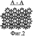
Фиг.2. Поперечный разрез участка активной зоны.Figure 2. Cross section of a core section.
5. Сведения, подтверждающие возможность осуществления изобретения5. Information confirming the possibility of carrying out the invention
Возможность осуществления изобретения проиллюстрируем конкретным примером.The possibility of carrying out the invention is illustrated by a specific example.
На фиг.1 изображена схема активной зоны заявляемого реактора. Она содержит нижнюю опорную платформу 1, на которой установлен боковой отражатель нейтронов 2 и укреплены графитовые трубы 3 для размещения стержней системы управления и аварийной защиты. Тепловыделяющая сборка 4 состоит из двух слоев вертикально расположенных твэлов 5. Каждый твэл имеет трубчатую оболочку внешним диаметром 20 мм и внутренним 12,7 мм, длиной 33 см, в которой установлено 6 топливных компактов диаметром 12,5 мм и высотой 50 мм, выполненных из микротвэлов и графитового связующего. Торцы оболочек заглушены турбулизаторами 6 в виде конических обтекателей с высотой конической части 25 мм.Figure 1 shows a diagram of the active zone of the inventive reactor. It contains a lower support platform 1 on which a lateral neutron reflector 2 is mounted and graphite tubes 3 are mounted to accommodate the rods of the control system and emergency protection. The fuel assembly 4 consists of two layers of vertically arranged fuel elements 5. Each fuel element has a tubular cladding with an external diameter of 20 mm and an internal 12.7 mm, a length of 33 cm, in which there are 6 fuel assemblies with a diameter of 12.5 mm and a height of 50 mm made of microfuel and graphite binder. The ends of the shells are drowned out by turbulators 6 in the form of conical fairings with a height of the conical part of 25 mm.
Твэлы собираются в тепловыделяющую сборку по 15 штук в ряд в квадратную решетку с шагом 30 мм в два слоя по высоте по 225 твэл в каждом слое. Из полного числа твэлов в сборке (450 шт.) часть (8 штук) убраны из углов. Шаг решетки при указанных размерах твэлов определен на основе расчетных исследований нейтронно-физических характеристик реактора с твердым теплоносителем и топливным циклом на основе обогащенного урана. Слои твэлов в сборке смещены относительно друг друга, например, как показано на фиг.2.The fuel rods are assembled into a fuel assembly of 15 pieces in a row in a square grid with a step of 30 mm in two layers with a height of 225 fuel rods in each layer. Of the total number of fuel rods in the assembly (450 pieces), part (8 pieces) are removed from the corners. The lattice pitch at the indicated fuel rod sizes is determined on the basis of computational studies of the neutron-physical characteristics of a reactor with a solid coolant and a fuel cycle based on enriched uranium. The fuel elements in the assembly are offset relative to each other, for example, as shown in FIG.
Дистанционирующие детали 7 из графитовых материалов (или тугоплавких металлов, или оксидов) связывают твэлы в сборках, расположены в области обтекателей и формируют зазоры между твэлами для прохода теплоносителя, выполняя роль дополнительных турбулизаторов, а также роль дистанционирующих и опорных элементов между ТВС.Spacer parts 7 made of graphite materials (or refractory metals, or oxides) connect the fuel rods in the assemblies, are located in the area of the fairings and form the gaps between the fuel rods for the coolant passage, acting as additional turbulators, as well as the role of the distance and support elements between the fuel assemblies.
Каждый нижний слой твэлов расположен по отношение к верхнему слою со сдвигом таким образом, что нижний слой твэлов располагается в середине пространства по теплоноситель верхнего слоя. Верхние обтекатели твэлов нижнего слоя находятся на уровне или выше конца нижнего обтекателя верхнего слоя твэлов.Each lower layer of fuel rods is located relative to the upper layer with a shift so that the lower layer of fuel rods is located in the middle of the space along the coolant of the upper layer. The upper fairings of the lower layer fuel rods are at or above the end of the lower fairing of the upper fuel layer.
Тепловыделяющая сборка с внешним размером сторон усеченного по углам квадрата ~460 мм устанавливается между графитовых труб 2 с внешним диаметром 55 мм и внутренним диаметром 25 мм. Трубы имеют высоту около 6 метров и образуют несущий каркас активной зоны. Внутри труб располагаются стрежни системы управления и защиты. Каждая тепловыделяющая сборка имеет монтажную высоту 67 см и 8 тепловыделяющих сборок, поставленных вертикально, образуют активную зону высотой 5,36 метра, при этом высота по топливным компактам составляет 4,8 метра. 16 слоев твэлов благодаря послойному сдвигу и расположению дистанционирующих деталей в области обтекателей хорошо размешивают теплоноситель и специальных турбулизаторов в области цилиндрических поверхностей твэлов не требуется. Монтажные зазоры между тепловыделяющими сборками и трубами системы управления и защиты реактора составляют около 1 мм, что позволяет производить свободную постановку сборок в активную зону и компенсирует температурные и радиационные эффекты формоизменения.A fuel assembly with an outer dimension of the sides of a square-truncated corner of ~ 460 mm is installed between graphite tubes 2 with an outer diameter of 55 mm and an inner diameter of 25 mm. Pipes have a height of about 6 meters and form a supporting frame of the core. Inside the pipes are rods of the control and protection system. Each fuel assembly has an installation height of 67 cm and 8 fuel assemblies, mounted vertically, form an active zone with a height of 5.36 meters, while the height of the fuel compacts is 4.8 meters. Due to the layer-by-layer shift and the arrangement of the spacer parts in the area of the fairings, 16 layers of fuel rods mix the coolant well and special turbulators in the area of the cylindrical surfaces of the fuel rods are not required. The mounting gaps between the fuel assemblies and the pipes of the reactor control and protection system are about 1 mm, which makes it possible to freely assemble the assemblies into the active zone and compensate for the temperature and radiation effects of the shape change.
В поперечном сечении площадь твэлов составляет 32% от площади ячейки сборки, а площадь труб под каналы стержней защиты и управления ~1%. Таким образом, по сравнению с прототипом площадь зазоров под теплоноситель увеличена в предлагаемой конструкции с 40 до 67%, что при фиксированной скорости позволяет увеличить теплосъем с активной зоны на ~65%.In the cross section, the area of the fuel rods is 32% of the area of the assembly cell, and the area of the pipes under the channels of the protection and control rods is ~ 1%. Thus, in comparison with the prototype, the gap area under the coolant is increased in the proposed design from 40 to 67%, which at a fixed speed allows you to increase heat removal from the core by ~ 65%.
Наружный диаметр активной зоны составляет ~9 метров, и вся активная зона состоит из тепловыделяющих сборок, поставленных свободно между трубами с упором внизу на дистанционирующие элементы нижних ТВС. Всего активная зона содержит ~2388 ТВС, расположенных вертикально по 8 штук в 299 столбах ТВС.The outer diameter of the active zone is ~ 9 meters, and the entire active zone consists of fuel assemblies placed freely between the pipes with an emphasis below on the spacing elements of the lower fuel assemblies. In total, the active zone contains ~ 2388 fuel assemblies arranged vertically, each of 8 pieces in 299 fuel assemblies.
Активная зона предложенной и описанной в данном примере конструкции обеспечивает тепловую мощность реактора 3750 МВТ при скорости теплоносителя 17 см/сек. При температурах теплоносителя на входе и выходе 500 и 900°С, расход теплоносителя составит 5,2 т/сек. Теплоноситель проходит активную зону за ~33 сек, скорость нагрева в среднем по активной зоне составляет ~12,5°С/с.The active zone of the design proposed and described in this example provides the thermal power of the 3750 MW reactor at a coolant speed of 17 cm / sec. At temperatures of the coolant at the inlet and outlet of 500 and 900 ° C, the flow rate of the coolant will be 5.2 t / s. The coolant passes the core in ~ 33 sec, the heating rate on average in the core is ~ 12.5 ° C / s.
Легко показать, что время тепловой релаксации теплонесущих частиц при снижении теплопроводности пирографита до ~8 Вт/м·град за счет влияния нейтронного облучения составляет около 0,3 с.It is easy to show that the thermal relaxation time of heat-carrying particles with a decrease in the thermal conductivity of pyrographite to ~ 8 W / m · deg due to the effect of neutron irradiation is about 0.3 s.
Таким образом, тепловая инерция теплонесущих частиц не играет существенную роль в предложенной конструкции и параметрах активной зоны.Thus, the thermal inertia of the heat-carrying particles does not play a significant role in the proposed design and core parameters.
Выполнены эксперименты, которые показали, что в предлагаемой конструкции активной зоны достигается эффективное перемешивание теплоносителя и обмен тепла между теплонесущими частицами (выравнивание температуры на выходе из реактора) практически без использования специальных турбулизаторов в областях боковых поверхностей твэлов и без образования застойных зон теплоносителя над твэлами и пустот ниже твэлов, т.е. обеспечена равномерность уран-графитового соотношения в активной зоне предложенного типа.Experiments were performed that showed that the proposed design of the active zone achieves efficient mixing of the coolant and heat exchange between the heat-carrying particles (equalizing the temperature at the outlet of the reactor) practically without using special turbulators in the areas of the side surfaces of the fuel rods and without the formation of stagnant coolant zones over the fuel rods and voids below the fuel rods, i.e. uniformity of the uranium-graphite ratio in the core of the proposed type is ensured.
Claims (1)
Priority Applications (1)
| Application Number | Priority Date | Filing Date | Title |
|---|---|---|---|
| RU2006124615/06A RU2315373C1 (en) | 2006-07-10 | 2006-07-10 | Core of high-temperature thermal reactor using finely dispersed solid coolant |
Applications Claiming Priority (1)
| Application Number | Priority Date | Filing Date | Title |
|---|---|---|---|
| RU2006124615/06A RU2315373C1 (en) | 2006-07-10 | 2006-07-10 | Core of high-temperature thermal reactor using finely dispersed solid coolant |
Publications (1)
| Publication Number | Publication Date |
|---|---|
| RU2315373C1 true RU2315373C1 (en) | 2008-01-20 |
Family
ID=39108801
Family Applications (1)
| Application Number | Title | Priority Date | Filing Date |
|---|---|---|---|
| RU2006124615/06A RU2315373C1 (en) | 2006-07-10 | 2006-07-10 | Core of high-temperature thermal reactor using finely dispersed solid coolant |
Country Status (1)
| Country | Link |
|---|---|
| RU (1) | RU2315373C1 (en) |
Citations (5)
| Publication number | Priority date | Publication date | Assignee | Title |
|---|---|---|---|---|
| GB915338A (en) * | 1960-03-14 | 1963-01-09 | Gen Nuclear Engineering Corp | A core for a thermal nuclear reactor |
| GB1309883A (en) * | 1971-03-18 | 1973-03-14 | Atomic Energy Authority Uk | Nuclear reactors |
| RU2166806C1 (en) * | 2000-02-09 | 2001-05-10 | Государственный научно-исследовательский институт Научно-производственное объединение "Луч" | Nuclear power reactor |
| RU2241263C1 (en) * | 2003-03-11 | 2004-11-27 | Федеральное государственное унитарное предприятие "Научно-исследовательский и конструкторский институт энерготехники им. Н.А. Доллежаля" | Thermal reactor core |
| RU2250519C2 (en) * | 2003-02-25 | 2005-04-20 | Федеральное государственное унитарное предприятие Государственный научный центр Российской Федерации Институт теоретической и экспериментальной физики | Thermal pulse reactor |
-
2006
- 2006-07-10 RU RU2006124615/06A patent/RU2315373C1/en not_active IP Right Cessation
Patent Citations (5)
| Publication number | Priority date | Publication date | Assignee | Title |
|---|---|---|---|---|
| GB915338A (en) * | 1960-03-14 | 1963-01-09 | Gen Nuclear Engineering Corp | A core for a thermal nuclear reactor |
| GB1309883A (en) * | 1971-03-18 | 1973-03-14 | Atomic Energy Authority Uk | Nuclear reactors |
| RU2166806C1 (en) * | 2000-02-09 | 2001-05-10 | Государственный научно-исследовательский институт Научно-производственное объединение "Луч" | Nuclear power reactor |
| RU2250519C2 (en) * | 2003-02-25 | 2005-04-20 | Федеральное государственное унитарное предприятие Государственный научный центр Российской Федерации Институт теоретической и экспериментальной физики | Thermal pulse reactor |
| RU2241263C1 (en) * | 2003-03-11 | 2004-11-27 | Федеральное государственное унитарное предприятие "Научно-исследовательский и конструкторский институт энерготехники им. Н.А. Доллежаля" | Thermal reactor core |
Similar Documents
| Publication | Publication Date | Title |
|---|---|---|
| RU2549369C2 (en) | Modular reactor for converting nuclear fission wastes | |
| RU2668230C1 (en) | Fast neutron nuclear reactor with liquid metal coolant | |
| US11367537B2 (en) | Annular nuclear fuel pellets with central burnable absorber | |
| WO2012135957A1 (en) | Molten salt nuclear reactor | |
| CN101911211A (en) | Nuclear reactor (optional), fuel assembly for a firing zone-regeneration zone subassembly of a nuclear reactor (optional), and fuel element for a fuel assembly | |
| US20040052326A1 (en) | Nuclear fuel assembly for a reactor cooled by light water comprising a nuclear fuel material in particle form | |
| TWI654619B (en) | Nuclear reactor fluence reduction systems | |
| KR102605338B1 (en) | Doppler reactivity augmentation device | |
| RU2277730C1 (en) | High-temperature uranium-graphite reactor core | |
| US9221093B2 (en) | Heat exchanger, methods therefor and a nuclear fission reactor system | |
| US9443623B2 (en) | Nuclear fission reactor fuel assembly and system configured for controlled removal of a volatile fission product and heat released by a burn wave in a traveling wave nuclear fission reactor and method for same | |
| Chen et al. | Preliminary thermal-hydraulic design and analysis of china lead alloy cooled research reactor (CLEAR-I) | |
| RU2315373C1 (en) | Core of high-temperature thermal reactor using finely dispersed solid coolant | |
| US9275760B2 (en) | Heat exchanger, methods therefor and a nuclear fission reactor system | |
| CN113130099A (en) | Compact-structure high-flux small-sized multipurpose lead-cooled fast reactor | |
| KR101017318B1 (en) | Support grid with mixed wing pattern for hydraulic balance | |
| RU6465U1 (en) | FUEL ASSEMBLY | |
| Gao et al. | Thermal-hydraulics design of water-cooled pressure tube blanket for a fusion driven subcritical reactor | |
| Nakano et al. | Conceptual reactor design study of very high temperature reactor (VHTR) with prismatic-type core | |
| US9659673B2 (en) | Nuclear fission reactor fuel assembly and system configured for controlled removal of a volatile fission product and heat released by a burn wave in a traveling wave nuclear fission reactor and method for same | |
| US9704604B2 (en) | Nuclear fission reactor fuel assembly and system configured for controlled removal of a volatile fission product and heat released by a burn wave in a traveling wave nuclear fission reactor and method for same | |
| JP3958545B2 (en) | Fuel assembly | |
| CN107967949A (en) | Lead base fast reactor quadrangle fuel assembly and its fast neutron reactor being used for | |
| RU2408095C1 (en) | High-temperature gas-cooled fast neutron nuclear reactor | |
| Nakano et al. | Conceptual reactor design study of VHTR with prismatic-type core |
Legal Events
| Date | Code | Title | Description |
|---|---|---|---|
| MM4A | The patent is invalid due to non-payment of fees |
Effective date: 20090711 |