RU2314373C1 - Crumples preventing attachment for hand-held iron - Google Patents
Crumples preventing attachment for hand-held iron Download PDFInfo
- Publication number
- RU2314373C1 RU2314373C1 RU2006114287/12A RU2006114287A RU2314373C1 RU 2314373 C1 RU2314373 C1 RU 2314373C1 RU 2006114287/12 A RU2006114287/12 A RU 2006114287/12A RU 2006114287 A RU2006114287 A RU 2006114287A RU 2314373 C1 RU2314373 C1 RU 2314373C1
- Authority
- RU
- Russia
- Prior art keywords
- wheels
- iron
- equipment according
- electric motors
- wheel
- Prior art date
Links
Images
Landscapes
- Irons (AREA)
Abstract
Description
Изобретение относится к оснасткам для ручных утюгов и предназначено для повышения качества процесса глажения, уменьшения количества замятий, складок одежды на ткани посредством растягивания оглаживаемой ткани перед подошвой утюга.The invention relates to tooling for hand irons and is intended to improve the quality of the ironing process, reduce the number of jams, folds of clothing on the fabric by stretching the ironed fabric in front of the sole of the iron.
Известен аналог заявленного изобретения, представляющий собой устройство для глажки. Название изобретения «IRONING DEVICE», номер патента №JP 2002355500, дата публикации 2002-12-10, автор KUROSE HIROSHI. Данное устройство оказывает разглаживающее действие на ткань посредством вращающихся цилиндров, катаемых по оглаживаемой поверхности. Реализация данного устройства полностью отменяет использование распространенного способа глажки посредством нагреваемой ровной поверхности (подошвы «обычного» ручного утюга).An analogue of the claimed invention is known, which is an ironing device. The name of the invention is “IRONING DEVICE”, patent number No. JP 2002355500, publication date 2002-12-10, author KUROSE HIROSHI. This device has a smoothing effect on the fabric by means of rotating cylinders rolled on the ironed surface. The implementation of this device completely eliminates the use of the common method of ironing by means of a heated flat surface (the sole of a “regular” hand iron).
Недостатком указанного аналога является то, что замена стандартного способа глажки на глажку катаемыми цилиндрами представляет технические трудности механизации данного способа, например сложность подвода пара к гладящей поверхности, сложность нагревания вращаемых цилиндров, избыточный расход тепла значительной открытой поверхностью цилиндров. С другой стороны, использование способа глажки нагреваемой ровной поверхностью утюга приводит при неосторожном обращении с утюгом к заглаживанию трудноразглаживаемых складок, замятий. Данный недостаток является следствием неполного расправления обрабатываемой ткани перед плоской подошвой утюга.The disadvantage of this analogue is that replacing the standard ironing method by ironing with rolling cylinders presents technical difficulties in mechanizing this method, for example, the difficulty of supplying steam to the ironing surface, the difficulty of heating the rotated cylinders, the excessive heat consumption of the large open surface of the cylinders. On the other hand, the use of the method of ironing with a heated flat surface of the iron results in careless handling of the iron to smooth out hard-to-smooth wrinkles and jams. This drawback is the result of incomplete expansion of the fabric to be processed in front of the flat sole of the iron.
Наиболее близким аналогом заявленного изобретения является оснастка для ручного утюга для предотвращения замятий, представленная в патенте RU №2036997, кл. D 06 F 75/38, 1995.The closest analogue of the claimed invention is a tool for a hand iron to prevent jams, presented in patent RU No. 2036997, class. D 06 F 75/38, 1995.
Задачей, решаемой в изобретении, является увеличение степени расправления оглаживаемой ткани перед подошвой утюга для уменьшения степени замятия ткани подошвой утюга.The problem solved in the invention is to increase the degree of expansion of the ironed fabric in front of the sole of the iron to reduce the degree of jamming of the fabric of the sole of the iron.
Техническим результатом изобретения повышение качества глажения за счет растягивания оглаживаемой ткани перед утюгом.The technical result of the invention is to improve the quality of ironing by stretching the ironed fabric in front of the iron.
Указанный технический результат достигается тем, что оснастка для ручного утюга для предотвращения замятий имеет одно или несколько колес, размещенных за периметром гладящей поверхности утюга. Обод колес может располагаться ниже основания гладящей поверхности так, чтобы в рабочем положении утюга колеса прижимались к оглаживаемой поверхности. Колеса сидят на единой или разделенной на независимые сегменты гибкой оси. Причем на одном сегменте оси может располагаться одно или несколько колес. Данная ось передает на колеса вращение от привода электромотора, одного или нескольких для отдельных сегментов оси. Оси удерживаются в креплениях (в которых свободно поворачиваются), которые через держатели подпружинены на корпусе утюга. На подпружиненных держателях креплений осей размещены выключатели, включающие при подпружинивании держателей питание электромоторов соответствующих осей. Это могут быть контактные выключатели, замыкающие при подпружинивании проводку электропитания соответствующих электромоторов. Причем в рабочем положении электромоторы вращают оси так, чтобы нижняя часть обода колес вращалась в направлении от периметра гладящей поверхности утюга.The specified technical result is achieved by the fact that the equipment for a manual iron to prevent jams has one or more wheels located outside the perimeter of the ironing surface of the iron. The wheel rim can be located below the base of the ironing surface so that in the working position of the iron, the wheels are pressed against the surface to be ironed. Wheels sit on a single or divided into independent segments of the flexible axis. Moreover, one or several wheels can be located on one axis segment. This axis transmits to the wheels rotation from the drive of the electric motor, one or more for individual segments of the axis. The axles are held in fasteners (in which they rotate freely), which through the holders are spring-loaded on the iron body. On the spring-loaded holders of the axle mounts, switches are placed that turn on the power of the electric motors of the corresponding axes when the holders are spring-loaded. It can be contact switches, closing when springing the power wiring of the respective electric motors. Moreover, in the working position, the electric motors rotate the axis so that the lower part of the wheel rim rotates in the direction from the perimeter of the ironing surface of the iron.
Для того чтобы при касании поверхности утюгом производить максимально сильное растягивающее оглаживаемую ткань действие в состав оснастки добавляется устройство управления вращения электромоторами. Функция его заключается в выдаче пиковой нагрузки на электромоторы при включении выключателя, расположенного на подпружиненном держателе оси. Также в состав оснастки может входить устройство управления электропитания электромоторами, которое включает/выключает электромоторы при включении/выключении выключателей, расположенный на держателях оси. Например, включает питание всех электромоторов при замыкании только одного выключателя, выключает электропитание электромоторов по «одному», т.е. при размыкании выключателя, соотнесенного определенному электромотору.In order to produce the most powerful stretching, ironed fabric action when touching the surface with an iron, a rotation control device for electric motors is added to the equipment. Its function is to issue a peak load on the electric motors when the circuit breaker is located, located on the spring-loaded axis holder. Also, the equipment may include a power control device for electric motors, which turns on / off electric motors when turning on / off switches located on the axis holders. For example, it turns on the power of all electric motors when only one circuit breaker is closed, turns off the power to electric motors one by one, i.e. when the circuit breaker associated with a particular motor is opened.
Для уменьшения сопротивления на трение при движении утюга поперек направления вращения обода колес (например, перпендикулярно или под углом) данные колеса могут приподыматься над поверхностью или может уменьшаться их давление на поверхность. Для этого в состав оснастки входят: устройство, определяющее направление движения утюга по оглаживаемой поверхности, устройство управляемого прижимания колес к поверхности, устройство управления прижиманием колес в зависимости от направления движения утюга. Причем колесо прижимается с тем большей силой (от нуля до максимальной), чем меньше значение угла между направлением движения утюга и направлением вращения обода колес. При увеличении угла нажатие на колесо ослабляется.To reduce the friction resistance when the iron moves across the direction of rotation of the wheel rim (for example, perpendicularly or at an angle) these wheels can rise above the surface or their pressure on the surface may decrease. To do this, the equipment includes: a device that determines the direction of motion of the iron on the surface to be ironed, a device for controlled pressing of wheels to the surface, a control device for pressing the wheels depending on the direction of motion of the iron. Moreover, the wheel is pressed with the greater force (from zero to maximum), the smaller the angle between the direction of motion of the iron and the direction of rotation of the wheel rim. As the angle increases, the wheel is weakened.
Также для облегчения скольжения утюга при движении против направления вращения обода колес в состав подпружиненных держателей креплений осей могут входить вибраторы, например, выполненные как электромагнитные вибраторы. Также функцию вибраторов может выполнять устройство воздействия на колеса.Also, to facilitate sliding of the iron when moving against the direction of rotation of the wheel rim, spring-loaded holders of axle mounts may include vibrators, for example, made as electromagnetic vibrators. Also, the function of the vibrators can perform the device impact on the wheels.
Колеса оснастки могут быть выполнены как протяженная гибкая трубка, нанизанная на гибкую ось. Например, вся оснастка может быть выполнена как одна гибкая трубка (вариант колеса с широким ободом), насаженная на одну гибкую ось.The wheels of the snap can be made as an extended flexible tube strung on a flexible axis. For example, all the equipment can be made as one flexible tube (a variant of the wheel with a wide rim), mounted on one flexible axis.
Для использования утюга обычным способом (без растяжения оглаживаемой ткани) добавляется механизм приподнимания колес оснастки над поверхностью/опускания обратно. Функцию данного механизма может выполнять устройство управляемого воздействия на колеса. Оснастка может быть закрыта под кожухом корпуса утюга (сверху и с боков). Вращение от электромоторов на гибкую ось может передаваться напрямую на гибкую ось или посредством шкивного механизма.To use the iron in the usual way (without stretching the ironed fabric), a mechanism for raising the tool wheels above the surface / lowering is added. The function of this mechanism can be performed by a device of controlled action on the wheels. The equipment can be closed under the casing of the iron body (top and sides). Rotation from electric motors to the flexible axis can be transmitted directly to the flexible axis or through a pulley mechanism.
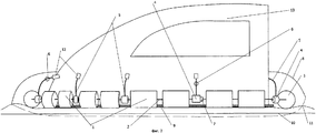
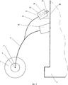
На фиг.1 представлен схематический вид утюга/оснастки снизу. На фиг.2 представлен схематический вид утюга/оснастки сбоку. На фиг.3 представлен схематический вид сбоку одного из держателей колес. Оснастка состоит из колес 1, насаженных на гибкую ось 1, проходящую вдоль периметра подошвы утюга 3 через крепления 4, расположенные на упругих держателях 5. На держателях 5 располагаются контактные выключатели 6, которые включают питание электромоторов 7. Оснастка прикрыта кожухом 8. Подошва утюга означена номером 9, поверхность означена номером 10, оглаживаемая ткань - номером 11. Вибраторы держателя 5 означены под номером 15. На держателях 5 располагается устройство воздействия на колеса 12, прижимающие колеса 1 к оглаживаемой поверхности при движении утюга 13 в направлении вращения обода колес 1 и отпускающие при движении в противоположном или перпендикулярном направлении. Направление движения утюга определяется с помощью устройства 14, в данном варианте размещенного на подошве 9 утюга. Устройство управляемого воздействия 12 на колеса состоит из (фиг.3) штыря 16, одним концом соединенного с держателем 5 оси 2. Другой конец подвижен и вставлен в сквозное отверстие 17 электромагнитной катушки 18, закрепленной на корпусе 20. Этот конец штыря 16 имеет ферромагнетик 19.Figure 1 presents a schematic view of the iron / tool bottom. Figure 2 presents a schematic side view of the iron / tooling. Figure 3 presents a schematic side view of one of the wheel holders. The equipment consists of
Принцип работы оснастки следующий. При касании подошвой утюга 9 оглаживаемой поверхности 10 упругие держатели 5 деформируются, что замыкает контактные выключатели 6. Это включает питание электромоторов 7, которые через гибкую ось 2 начинают вращать колеса 1. Колеса 1 вращаются так, что движение нижней части колес (в свободном состоянии) направлено от подошвы утюга 9. Так как колеса прижаты через упругие держатели 5 к поверхности 10 и в идеале не прокручиваются, это создает постоянное усилие, направленное в стороны от подошвы утюга 9 и растягивающее ткань 11 в стороны. При включении вибраторов 15 колеса 1 вибрируют, что уменьшает усилие, тратимое на их перемещение при движении утюга против направления движения колес (например, перпендикулярно движению колес). Также функцию вибраторов 15 может выполнять устройство 12 воздействия на колеса, производящее частые прижимание/отпускание колес с малой амплитудой. При необходимости колеса оснастки могут быть приподняты над поверхностью с помощью дополнительного механизма (не показан), функцию данного механизма также может выполнять устройство 12 воздействия на колеса, приподымающее над поверхностью все колеса 1 оснастки.The principle of the snap is as follows. When the sole of the
Для того чтобы уменьшить сопротивление на трение при движении утюга не в направлении вращения колес 1 (например, перпендикулярно или под углом) данные колеса приподымаются над поверхностью или уменьшается их давление на поверхность. Для этого устройство определения направления движения 14 выдает для устройства управления воздействием на колеса информацию о направлении движения.In order to reduce the friction resistance when the iron does not move in the direction of rotation of the wheels 1 (for example, perpendicularly or at an angle), these wheels rise above the surface or their pressure on the surface decreases. For this, the device for determining the direction of movement 14 provides the device for controlling the effect on the wheels of information about the direction of movement.
Устройство, определяющее направление движения утюга, может быть выполнено аналогично применяемым в манипуляторах, типа «компьютерная мышь». Например, посредством катаемого по поверхности шара с датчиками вращения шара или посредством видеокамеры, отслеживающей перемещение подсвечиваемой текстуры поверхности. Также данное устройство может быть выполнено как инерционный датчик ускорения/скорости.A device that determines the direction of motion of the iron, can be performed similarly used in manipulators, such as "computer mouse". For example, by means of a ball rolling on the surface with ball rotation sensors or by means of a video camera tracking the movement of the illuminated surface texture. Also, this device can be performed as an inertial acceleration / speed sensor.
Устройство управления прижиманием колес включает вычислительный блок, рассчитывающий для каждого колеса значение тригонометрической функции, например значение косинуса угла между направлением вращения обода колеса и направлением движением утюга. Найденное значение тригонометрической функции модифицирует по некоторому алгоритму (например, умножением) максимально допустимую величину усилия прижатия колес к поверхности или производную от усилия, например, силу тока, подаваемую на устройство прижатия колес. Затем найденное значение усилия применяется в устройстве прижимания соответствующего колеса, например, выдающего рассчитанную силу тока для него.The wheel pressing control device includes a computing unit calculating a trigonometric function value for each wheel, for example, the cosine of the angle between the direction of rotation of the wheel rim and the direction of motion of the iron. The found value of the trigonometric function modifies, according to some algorithm (e.g., multiplication), the maximum allowable value of the force of pressing the wheels to the surface or the derivative of the force, for example, the current supplied to the device of pressing the wheels. Then, the found value of the force is applied in the pressing device of the corresponding wheel, for example, issuing the calculated current strength for it.
Само устройство управляемого воздействия на колеса 12 может или дополнительно прижимать колеса к поверхности, или приподнимать колеса над поверхностью для ослабления прижимающей силы упругого штыря держателя 5. Для реализации первого варианта с дополнительным прижатием колес конец штыря 16 с ферромагнетиком 19 может быть вставлен в отверстие 17 электромагнитной катушки 18 так, чтобы при подаче тока на катушку он втягивался внутрь катушки 18 и выталкивал другой конец по направлению из катушки. При уменьшении силы нажатия на колесо оно будет приподыматься на упругих держателях 5. Аналогично, для реализации другого варианта приподнимания колеса над поверхностью для ослабления прижимающей силы упругого штыря держателя 5, конец с ферромагнетиком 19 может быть вставлен в катушку 18 так, чтобы при подаче тока на катушку конец с ферромагнетиком втягивался внутрь катушки 18 и тянул за собой другой конец по направлению к катушке.The device of the controlled action on the
Claims (20)
Priority Applications (1)
| Application Number | Priority Date | Filing Date | Title |
|---|---|---|---|
| RU2006114287/12A RU2314373C1 (en) | 2006-04-26 | 2006-04-26 | Crumples preventing attachment for hand-held iron |
Applications Claiming Priority (1)
| Application Number | Priority Date | Filing Date | Title |
|---|---|---|---|
| RU2006114287/12A RU2314373C1 (en) | 2006-04-26 | 2006-04-26 | Crumples preventing attachment for hand-held iron |
Publications (1)
| Publication Number | Publication Date |
|---|---|
| RU2314373C1 true RU2314373C1 (en) | 2008-01-10 |
Family
ID=39020188
Family Applications (1)
| Application Number | Title | Priority Date | Filing Date |
|---|---|---|---|
| RU2006114287/12A RU2314373C1 (en) | 2006-04-26 | 2006-04-26 | Crumples preventing attachment for hand-held iron |
Country Status (1)
| Country | Link |
|---|---|
| RU (1) | RU2314373C1 (en) |
Cited By (1)
| Publication number | Priority date | Publication date | Assignee | Title |
|---|---|---|---|---|
| CN117005176A (en) * | 2022-05-06 | 2023-11-07 | Seb公司 | Household appliances including an iron and a base connected to the iron by a cable |
Citations (4)
| Publication number | Priority date | Publication date | Assignee | Title |
|---|---|---|---|---|
| RU2036997C1 (en) * | 1992-05-27 | 1995-06-09 | Сальников Владимир Константинович | Electric iron |
| RU2094553C1 (en) * | 1994-03-31 | 1997-10-27 | Общество с ограниченной ответственностью Малое предприятие Фирма "Криэко" | Electric iron |
| RU2149935C1 (en) * | 1996-08-24 | 2000-05-27 | Ровента-Верке ГмбХ | Electric iron with ironing sole |
| GB2385603A (en) * | 2002-02-23 | 2003-08-27 | Salton Europ Ltd | Iron with retractable sole plate |
-
2006
- 2006-04-26 RU RU2006114287/12A patent/RU2314373C1/en not_active IP Right Cessation
Patent Citations (4)
| Publication number | Priority date | Publication date | Assignee | Title |
|---|---|---|---|---|
| RU2036997C1 (en) * | 1992-05-27 | 1995-06-09 | Сальников Владимир Константинович | Electric iron |
| RU2094553C1 (en) * | 1994-03-31 | 1997-10-27 | Общество с ограниченной ответственностью Малое предприятие Фирма "Криэко" | Electric iron |
| RU2149935C1 (en) * | 1996-08-24 | 2000-05-27 | Ровента-Верке ГмбХ | Electric iron with ironing sole |
| GB2385603A (en) * | 2002-02-23 | 2003-08-27 | Salton Europ Ltd | Iron with retractable sole plate |
Cited By (2)
| Publication number | Priority date | Publication date | Assignee | Title |
|---|---|---|---|---|
| CN117005176A (en) * | 2022-05-06 | 2023-11-07 | Seb公司 | Household appliances including an iron and a base connected to the iron by a cable |
| CN117005176B (en) * | 2022-05-06 | 2025-10-24 | Seb公司 | Household appliances including an iron and a base connected to the iron by a cord |
Similar Documents
| Publication | Publication Date | Title |
|---|---|---|
| KR101856524B1 (en) | Steering wheel for vehicle | |
| JP3160795U (en) | Motor driven passive stretch recovery training machine | |
| US6685659B2 (en) | Individual controlled body massage device | |
| WO2013063911A1 (en) | Labour-saving apparatus for testing no-load operation of manual chain hoist | |
| RU2314373C1 (en) | Crumples preventing attachment for hand-held iron | |
| CN105726274A (en) | Automatic back scratcher capable of changing touch sense and speed | |
| CN209649728U (en) | A kind of novel Pyrograph machine | |
| EP2218574A1 (en) | Heat transfer press | |
| KR101729435B1 (en) | Electric iron with safety module | |
| JP4062241B2 (en) | Massage machine | |
| JP3128776B2 (en) | Sheet press machine | |
| JP4692110B2 (en) | Massage machine | |
| JP5026878B2 (en) | Shirt side waistline device | |
| US5335431A (en) | Pressing machine for unfolding seamed and folded margins in clothing | |
| WO2013153463A2 (en) | Automatic triple motion steam iron | |
| CN218779196U (en) | Clothing ironing device for tailoring | |
| JP2008049177A (en) | Massaging machine | |
| CN112878013A (en) | Folding mechanism of fabric | |
| CN214344414U (en) | Ironing device for doll hair | |
| CN220132611U (en) | Ironing finishing equipment for business suit | |
| CN204849305U (en) | A Handheld Household Electric Sewing Machine Speed Controller | |
| KR20090024348A (en) | Tension Method of Shirt Side and Torso Tension Device Used in This Method | |
| CN214074150U (en) | Lower limb exercise rehabilitation device | |
| CN210481838U (en) | Automatic clothes folding machine | |
| WO2007034180A1 (en) | Improved steam press |
Legal Events
| Date | Code | Title | Description |
|---|---|---|---|
| MM4A | The patent is invalid due to non-payment of fees |
Effective date: 20080427 |