RU2314130C2 - Disposable syringe - Google Patents
Disposable syringe Download PDFInfo
- Publication number
- RU2314130C2 RU2314130C2 RU2005136445/14A RU2005136445A RU2314130C2 RU 2314130 C2 RU2314130 C2 RU 2314130C2 RU 2005136445/14 A RU2005136445/14 A RU 2005136445/14A RU 2005136445 A RU2005136445 A RU 2005136445A RU 2314130 C2 RU2314130 C2 RU 2314130C2
- Authority
- RU
- Russia
- Prior art keywords
- tube
- cylinder
- disposable syringe
- protrusion
- adapter tube
- Prior art date
Links
Images


Classifications
-
- A—HUMAN NECESSITIES
- A61—MEDICAL OR VETERINARY SCIENCE; HYGIENE
- A61M—DEVICES FOR INTRODUCING MEDIA INTO, OR ONTO, THE BODY; DEVICES FOR TRANSDUCING BODY MEDIA OR FOR TAKING MEDIA FROM THE BODY; DEVICES FOR PRODUCING OR ENDING SLEEP OR STUPOR
- A61M5/00—Devices for bringing media into the body in a subcutaneous, intra-vascular or intramuscular way; Accessories therefor, e.g. filling or cleaning devices, arm-rests
- A61M5/178—Syringes
- A61M5/31—Details
- A61M5/32—Needles; Details of needles pertaining to their connection with syringe or hub; Accessories for bringing the needle into, or holding the needle on, the body; Devices for protection of needles
- A61M5/3205—Apparatus for removing or disposing of used needles or syringes, e.g. containers; Means for protection against accidental injuries from used needles
- A61M5/321—Means for protection against accidental injuries by used needles
- A61M5/322—Retractable needles, i.e. disconnected from and withdrawn into the syringe barrel by the piston
- A61M5/3221—Constructional features thereof, e.g. to improve manipulation or functioning
- A61M2005/3223—Means impeding or disabling repositioning of used needles at the syringe nozzle
- A61M2005/3224—Means to disalign the needle tip and syringe nozzle
Abstract
Description
Область техникиTechnical field
Данное изобретение относится к шприцу, а более конкретно к одноразовому шприцу. Несмотря на то, что данное изобретение пригодно для широкой области применений, оно особенно подходит для создания более безопасного одноразового шприца с усиленными мерами безопасности.This invention relates to a syringe, and more particularly to a disposable syringe. Although this invention is suitable for a wide range of applications, it is particularly suitable for creating a safer disposable syringe with enhanced safety measures.
Предпосылки изобретенияBACKGROUND OF THE INVENTION
В общем случае шприц представляет собой медицинское устройство, используемое для введения инъекционной жидкости (например, лекарства) в тело (или вены) пациента. Кроме того, шприц обычно после использования выбрасывается, чтобы предотвратить заражение третьего лица болезнями, переносимыми пациентом. Ниже со ссылкой на прилагаемые чертежи приводится описание одноразового шприца, известного из уровня техники.In general, a syringe is a medical device used to inject injection liquid (e.g., medicine) into a patient's body (or veins). In addition, the syringe is usually thrown away after use to prevent the third person from becoming infected with diseases borne by the patient. Below with reference to the accompanying drawings is a description of a disposable syringe known from the prior art.
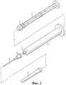
На фиг.1 представлен в аксонометрии известный из уровня техники разобранный одноразовый шприц, выполненный в соответствии с первым вариантом выполнения.Figure 1 presents in a perspective view of the prior art disassembled disposable syringe made in accordance with the first embodiment.
В соответствии с фиг.1 известный из уровня техники одноразовый шприц состоит из цилиндра 1, в котором имеется полое пространство, и соединительной трубки 2, выполненной со ступенчатым перепадом на переднем конце цилиндра 1. Одноразовый шприц, известный из уровня техники, также содержит шток 3, перемещающийся внутри цилиндра 1 взад и вперед по его длине. На переднем конце штока 3 выполнен поршень 4, который перемещается вместе со штоком 3, герметично прилегая к внутренней поверхности цилиндра 1.In accordance with FIG. 1, a disposable syringe known from the prior art consists of a
Держатель 5 иглы шприца прикреплен с возможностью отсоединения к внешней поверхности соединительной трубки 2, выполненной на цилиндре 1. В держателе 5 иглы шприца закреплена игла 6 шприца. Кроме того, прикреплен защитный колпачок 7, полностью накрывающий держатель 5 и иглу 6 шприца.The
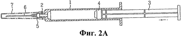
На фиг.2А представлен пример этапа всасывания инъекционной жидкости в шприц.On figa presents an example of the stage of absorption of the injection fluid into the syringe.
В соответствии с фиг.2А защитный колпачок 7, предохраняющий иглу 6 шприца, сначала отделяют от держателя 5 иглы шприца. Затем шток 3, вставленный в полое пространство цилиндра 1, проталкивают вперед к переднему концу цилиндра 1. Затем конец иглы 6 шприца вводят и погружают в контейнер с инъекционной жидкостью (не показан). После этого шток 3 с прикрепленным к нему поршнем 4 отводят назад, создавая тем самым всасывающее усилие внутри полого пространства цилиндра 1. Благодаря всасывающему усилию происходит всасывание инъекционной жидкости в цилиндр 1 через иглу 6 шприца, прикрепленную к держателю 5 иглы шприца, вследствие чего происходит заполнение полого пространства цилиндра 1.In accordance with FIG. 2A, the
На фиг.2В представлен пример этапа введения инъекционной жидкости пациенту.FIG. 2B shows an example of a step for administering injection fluid to a patient.
В соответствии с фиг.2В пользователь прокалывает иглой 6 шприца кожу пациента, затем толкает шток 3 для перемещения поршня 4 к переднему концу цилиндра 1. На этой стадии внутри полого пространства цилиндра 1, а более конкретно у переднего конца поршня 4 (показан в левой части фиг.2В), создается давление. Таким образом, благодаря давлению, создаваемому поршнем 4, инъекционная жидкость, заполнившая полое пространство цилиндра 1, вытекает из цилиндра 1 через соединительную трубку 2, выполненную на краю цилиндра 1.2B, the user punctures the patient’s skin with a
Инъекционная жидкость, проходящая через соединительную трубку 2, продолжает вытекать через иглу 6 шприца, закрепленную в держателе 5 иглы шприца, и вводится в кожу и вены пациента. Во время этого процесса инъекционная жидкость не просачивается из соединительной трубки 2 и держателя 5 иглы шприца благодаря креплению держателя 5 иглы шприца к соединительной трубке 2 на посадке с натягом.Injection fluid passing through the connecting
Между тем, после использования шприца защитный колпачок безопасно и полностью прикрепляют к держателю 5 иглы шприца, закрывая и защищая иглу 6 шприца для того, чтобы безопасно избавиться от использованного шприца.Meanwhile, after using the syringe, the protective cap is securely and completely attached to the
Описанный выше одноразовый шприц обладает преимуществом, которое заключается в том, что инъекционная жидкость не просачивается из шприца во время проведения инъекции. Однако при повторном надевании защитного колпачка 7 на держатель 5 иглы шприца после использования пользователь или третье лицо могут пораниться иглой шприца. Кроме того, когда защитный колпачок отсоединен от шприца при избавлении от медицинских отходов, другое третье лицо (т.е. лицо, имеющее дело с медицинскими отходами) также может пораниться иглой шприца.The disposable syringe described above has the advantage that the injection liquid does not leak out of the syringe during the injection. However, when reinserting the
Поэтому для предотвращения возникновения подобных небольших травм производители медицинских инструментов, аппаратов и устройств разрабатывают новые типы одноразовых шприцов с повышенными функциями безопасности.Therefore, to prevent the occurrence of such minor injuries, manufacturers of medical instruments, apparatus and devices are developing new types of disposable syringes with enhanced safety functions.
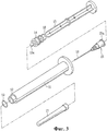
На фиг.3 представлен в аксонометрии разобранный одноразовый шприц, выполненный в соответствии со вторым вариантом выполнения, известным из уровня техники.Figure 3 presents in perspective a disassembled disposable syringe made in accordance with the second embodiment, known from the prior art.
Шприц, известный из уровня техники, содержит цилиндр 11 с соединительной трубкой 12, выполненной со ступенчатым перепадом на переднем краю цилиндра 11, а также шток 13 с прикрепленным к нему поршнем 14. По внутренней периферии соединительной трубки 12 выполнено уплотнительное кольцо 19, предназначенное для герметичного крепления к держателю 15 иглы шприца. Кроме того, на заднем конце по внешней периферии держателя 15 иглы шприца выполнен фланец 15а.The syringe, known from the prior art, contains a
Оба конца цилиндра 11 соединены друг с другом с образованием полого пространства внутри цилиндра. На переднем конце цилиндра 11 выполнена соединительная трубка 12 со ступенчатым перепадом. И, наконец, к внешней поверхности соединительной трубки 12 прикреплен с возможностью отделения защитный колпачок 17, предназначенный для того, чтобы закрывать и защищать иглу 16 шприца.Both ends of the
В полое пространство цилиндра 11 вставлен шток 13, перемещающийся взад и вперед внутри цилиндра 11 по его длине. На переднем конце штока 13 выполнен поршень 14, перемещающийся вдоль цилиндра 1, герметично прилегая к его внутренней поверхности и создавая тем самым давление или усилие всасывания. Кроме того, на переднем конце штока 13 выполнен соединительный элемент 13а, соответствующий соединительному выступу держателя 15 иглы. И наконец, на штоке 13 вблизи поршня 14 выполнена перерезающая канавка 18, позволяющая легко сломать шток 13.A
Держатель 15 иглы шприца вводится в указанный цилиндр через полое пространство так, что оказывается обращенным к переднему концу соединительной трубки 12. Для более прочного крепления к соединительной трубке 12 между держателем 15 иглы шприца и соединительной трубкой 12 необходимо наличие контактной поверхности. Однако при креплении держателя 15 иглы шприца к соединительной трубке 12 на посадке с натягом может получиться так, что после проведения инъекции будет невозможно втянуть держатель 15 иглы шприца в полое пространство цилиндра. Поэтому при креплении держателя 15 иглы шприца к соединительной трубке 12 необходимо сохранить небольшой зазор. За счет ступенчатого перепада между цилиндром 11 и соединительной трубкой 12 фланец 15а входит в соприкосновение с внутренним уступом, образованным внутри цилиндра 11.The
Уплотнительное кольцо 19 прикреплено к внутренней периферии соединительной трубки 12, предотвращая просачивание инъекционной жидкости через небольшой зазор между соединительной трубкой 12 и держателем 15 иглы шприца. Более конкретно, уплотнительное кольцо 19 поддерживает герметичную изоляцию между соединительной трубкой 12 и держателем 15 иглы шприца.O-
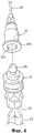
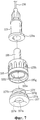
На фиг.4 представлен в аксонометрии держатель иглы шприца и шток, отсоединенные от одноразового шприца, выполненного в соответствии со вторым вариантом выполнения, известным из уровня техники.FIG. 4 is a perspective view of a syringe needle holder and a rod disconnected from a disposable syringe made in accordance with a second embodiment of the prior art.
На заднем конце держателя 15 иглы шприца по внутренней периферии выполнена пара выступов 15b, обращенных друг к другу. На переднем конце штока 13 выполнен соединительный элемент 13а, который соединяется с выступами 15b при проталкивании штока к переднему концу цилиндра 11. Кроме того, соединительный элемент 13а и каждый выступ 15b имеют наклонную поверхность, предназначенную для сведения к минимуму натяга, вызываемого контактом при введении переднего конца штока 13 в держатель 15 иглы шприца.At the rear end of the
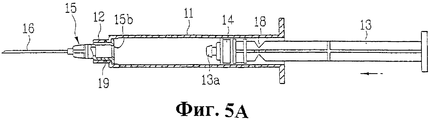
На фиг.5А-5Е представлены поперечные разрезы, демонстрирующие этапы использования одноразового шприца, выполненного в соответствии со вторым вариантом выполнения, известным из уровня техники.5A-5E are cross-sectional views illustrating the steps of using a disposable syringe according to a second embodiment of the prior art.
Для введения инъекционной жидкости пациенту сначала необходимо осуществить всасывание инъекционной жидкости в полое пространство цилиндра. Однако поскольку этап всасывания инъекционной жидкости в шприц идентичен описанному выше при рассмотрении фиг.2А, то для упрощения описание не приводится.To administer injection fluid, the patient must first suck the injection fluid into the hollow space of the cylinder. However, since the step of suctioning the injection liquid into the syringe is identical to that described above with reference to FIG. 2A, a description is not given for simplicity.
На фиг.5А представлено заполненное инъекционной жидкостью полое пространство цилиндра 11, показанное в виде левосторонней области шприца. Процесс введения инъекционной жидкости пациенту аналогичен описанному при рассмотрении фиг.2b, и поэтому его описание для упрощения также не приводится.On figa presents a filled with injection fluid hollow space of the
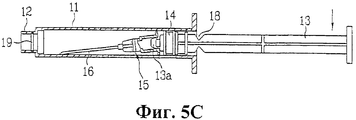
На фиг.5В и 5С проиллюстрировано завершение проведения инъекции и этап втягивания держателя иглы шприца обратно в цилиндр.5B and 5C illustrate the completion of an injection and the step of pulling the syringe needle holder back into the cylinder.
В соответствии с фиг.5В и 5С при завершении введения инъекционной жидкости держатель 15 иглы шприца входит в соединительную трубку 12, выполненную на цилиндре 11. На этой стадии фланец 15а, который выполнен на заднем конце по внешней периферии держателя 15 иглы шприца, входит в соприкосновение с внутренним уступом, выполненным внутри цилиндра 11 за счет ступенчатого перепада между цилиндром 11 и соединительной трубкой 12. Таким образом, фланец 15а ограничивает дальнейшее продвижение вперед держателя 15 иглы шприца.In accordance with FIGS. 5B and 5C, upon completion of the injection of the injection fluid, the
Тем временем, после завершения проведения инъекции, иглу 16 шприца вытягивают из кожи пациента. Затем шток 13 оттягивают в направлении, противоположном пациенту (т.е. назад), держатель 15 иглы шприца также оттягивают назад вместе со штоком 13. Это осуществляется за счет соединения соединительного элемента 13а с выступами 15b держателя 15 иглы шприца.Meanwhile, after completion of the injection, the
Затем шток 13 оттягивают далее к заднему концу цилиндра 11 с тем, чтобы держатель 15 иглы шприца был полностью втянут в цилиндр 11. Держатель 15 иглы шприца удерживается соединительным элементом 13а штока 13. Другими словами, поскольку наружный диаметр фланца 15а меньше внутреннего диаметра цилиндра 11, держатель 15 иглы шприца подвешивается на переднем конце штока 13. Поэтому из-за эксцентричности центра тяжести держатель 15 иглы шприца, имеющий точку соединения между держателем 15 и передним концом штока 13 в качестве его опорной точки, наклоняется вниз (т.е. в направлении действия силы тяжести). На этой стадии только передний конец иглы 16 шприца входит в соприкосновение с внутренней поверхностью цилиндра 11. Кроме того, между контактной поверхностью цилиндра 11 и держателем 15 иглы шприца сохраняется постоянный угол наклона.Then, the
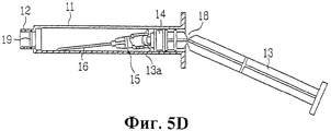
На фиг.5D и 5Е проиллюстрированы этапы предотвращения извлечения держателя иглы шприца из цилиндра.Figures 5D and 5E illustrate the steps of preventing the syringe needle holder from being pulled out of the cylinder.
В соответствии с фиг.5D и 5Е перерезающую канавку 18, выполненную на штоке 13, оттягивают назад так, что она оказывается вблизи наружной стороны цилиндра 11. Затем на шток 13 несколько раз нажимают вниз в направлении, перпендикулярном штоку 13, ломая его по выполненной на нем перерезающей канавке 18. Впоследствии отломанную часть штока 13 помещают так, чтобы она располагалась параллельно цилиндру 11 и была обращена внутрь его переднего конца. Затем вставляют отломанную часть штока 13 через соединительную трубку 12, перекрывая передний конец цилиндра и предотвращая тем самым выпадение или выскальзывание из цилиндра 11 держателя 15 иглы шприца, удерживаемого внутри цилиндра 11.In accordance with fig.5D and 5E, the cutting
Однако описанный выше одноразовый шприц, известный из уровня техники, имеет недостаток, заключающийся в необходимости использования уплотнительного кольца.However, the above-described disposable syringe, known from the prior art, has the disadvantage that it requires the use of an o-ring.
Уплотнительное кольцо является чувствительным даже к малейшему внешнему давлению, поэтому оно легко деформируется. Поэтому, если уплотнительное кольцо не может быть устойчиво вставлено в соединительную трубку, шприц может стать дефектным.The o-ring is sensitive to even the slightest external pressure, so it is easily deformed. Therefore, if the o-ring cannot be stably inserted into the connecting tube, the syringe may become defective.
Кроме того, для уменьшения дефектности одноразовых шприцов, в которых используется уплотнительное кольцо, в производственной линии требуется применение широкого диапазона сложных вспомогательных технологических устройств, что вызывает увеличение себестоимости продукции.In addition, to reduce the defectiveness of disposable syringes that use a sealing ring, a wide range of complex auxiliary technological devices is required in the production line, which causes an increase in the cost of production.
И наконец, поскольку дефектность уплотнительного кольца невозможно распознать невооруженным взглядом, то при использовании шприца, изготовленного с дефектным уплотнительным кольцом, во время процесса проведения инъекции возможно просачивание инъекционной жидкости из шприца.And finally, since the defectiveness of the sealing ring cannot be recognized with the naked eye, when using a syringe made with a defective sealing ring, the injection fluid may leak from the syringe during the injection process.
Сущность изобретенияSUMMARY OF THE INVENTION
Цель данного изобретения, поставленная для решения проблемы, заключается в создании одноразового шприца с уменьшенной производственной дефектностью, что позволяет использовать одноразовый шприц более безопасно.The purpose of this invention, to solve the problem, is to create a disposable syringe with reduced production defects, which allows the use of a disposable syringe more safely.
Другая цель данного изобретения, поставленная для решения проблемы, заключается в создании одноразового шприца, не требующего вспомогательных технологических устройств в производственной линии для снижения дефектности одноразовых шприцов, и, тем самым, уменьшения стоимости производства.Another objective of this invention, set to solve the problem, is to create a disposable syringe that does not require auxiliary technological devices in the production line to reduce the defectiveness of disposable syringes, and thereby reduce the cost of production.
Дополнительная цель данного изобретения, поставленная для решения проблемы, заключается в создании одноразового шприца, позволяющего во время процесса его сборки легко определить невооруженным глазом дефектность переходной трубки и вставной трубки, в случае ее наличия, за счет чего при использовании одноразового шприца увеличивается надежность продукции.An additional objective of the present invention, set to solve the problem, is to create a disposable syringe that allows the defective adapter tube and insert tube, if any, to be easily detected with the naked eye during the assembly process, thereby increasing product reliability when using a disposable syringe.
Цель данного изобретения может быть достигнута созданием одноразового шприца, содержащего цилиндр, открытый с обоих концов, переходную трубку, вставленную с одной стороны цилиндра, вставную трубку, введенную в переходную трубку и обеспечивающую герметичный контакт переходной трубки с внутренней периферией цилиндра, а также поршень, вставленный в цилиндр.The purpose of this invention can be achieved by creating a disposable syringe containing a cylinder open at both ends, a transition tube inserted on one side of the cylinder, an insertion tube inserted into the transition tube and providing a tight contact of the transition tube with the inner periphery of the cylinder, and a piston inserted into the cylinder.
Предпочтительней, чтобы переходная трубка имела элемент малого диаметра и элемент большого диаметра, имеющий внутренний диаметр, превышающий диаметр элемента малого диаметра, а вставная трубка имела первый контактирующий элемент, находящийся в герметичном контакте с внутренней периферией элемента переходной трубки с большим диаметром, и вставной элемент, который вставлен в элемент малого диаметра. Также предпочтительней, чтобы предлагаемый шприц дополнительно содержал второй контактирующий элемент, выполненный с расширением у заднего конца первого контактирующего элемента и находящийся в контакте с внутренней периферией цилиндра.It is preferable that the adapter tube has an element of small diameter and an element of large diameter having an inner diameter greater than the diameter of the element of small diameter, and the insertion tube has a first contacting element in tight contact with the inner periphery of the element of the adapter tube with a large diameter, and the insertion element which is inserted into the element of small diameter. It is also preferable that the proposed syringe further comprises a second contacting element, made with expansion at the rear end of the first contacting element and in contact with the inner periphery of the cylinder.
Предпочтительней, чтобы на элементе малого диаметра переходной трубки был выполнен второй соединительный элемент, а на вставном элементе вставной трубки был выполнен второй выступ, соответствующий второму соединительному элементу переходной трубки. Предпочтительней, чтобы второй выступ вставной трубки был выполнен только на передней части вставной трубки. Также предпочтительней, чтобы второй выступ вставной трубки был выполнен с наклоном к переднему концу вставной трубки.It is preferable that a second connecting element is formed on the small diameter element of the adapter tube, and a second protrusion corresponding to the second adapter element of the adapter tube is made on the insertion element of the insertion tube. Preferably, the second protrusion of the insertion tube is made only on the front of the insertion tube. It is also preferable that the second protrusion of the insertion tube be inclined to the front end of the insertion tube.
Предпочтительней, чтобы на внутренней периферии у заднего конца вставной трубки был выполнен первый соединительный элемент, а у переднего конца поршня был выполнен первый выступ, соответствующий первому соединительному элементу вставной трубки. Также предпочтительней, чтобы первый соединительный элемент вставной трубки или первый выступ поршня был выполнен с наклоном. Предпочтительней, чтобы наружный диаметр первого контактирующего элемента вставной трубки превышал внутренний диаметр элемента большого диаметра переходной трубки.It is preferable that the first connecting element is formed on the inner periphery at the rear end of the insertion tube, and the first protrusion corresponding to the first connecting element of the insertion tube is made at the front end of the piston. It is also preferred that the first connecting element of the insertion tube or the first protrusion of the piston is inclined. It is preferable that the outer diameter of the first contact element of the insertion tube exceed the inner diameter of the element of the large diameter of the adapter tube.
Также предпочтительней, чтобы на внешней периферии переходной трубки был выполнен выступ, а на внутренней периферии цилиндра был выполнен паз, соответствующий выступу переходной трубки. Предпочтительней, чтобы по меньшей мере переходная трубка или вставная трубка была выполнена из упругого материала. Кроме того предпочтительней, чтобы на внешней периферии переходной трубки был выполнен выступающий элемент, а на внутренней периферии цилиндра был выполнен паз для вставки, соответствующий выступающему элементу переходной трубки.It is also preferable that a protrusion is made on the outer periphery of the transition tube, and a groove corresponding to the protrusion of the transition tube is made on the inner periphery of the cylinder. Preferably, at least the adapter tube or insertion tube is made of an elastic material. In addition, it is preferable that a protruding element is formed on the outer periphery of the adapter tube, and an insertion groove corresponding to the protruding element of the adapter tube is made on the inner periphery of the cylinder.
Предпочтительней, чтобы у переднего конца переходной трубки была выполнена с расширением трубка для выпуска инъекционной жидкости. Здесь предпочтительней, чтобы с трубкой для выпуска инъекционной жидкости был соединен держатель иглы шприца.It is preferable that at the front end of the adapter tube an extension tube for extending the injection liquid is made with expansion. Here, it is preferable that a syringe needle holder is connected to the injection tube.
Также предпочтительней, чтобы на переднем конце цилиндра была выполнена соединительная трубка, на внутренней периферии соединительной трубки был выполнен выступ, а на держателе иглы шприца был выполнен фланец, соответствующий выступу соединительной трубки. Предпочтительней, чтобы у переднего конца поршня был эксцентрично выполнен создающий давление элемент, вставленный в трубку для выпуска инъекционной жидкости. Здесь также предпочтительней, чтобы создающий давление элемент был выполнен из упругого материала.It is also preferable that a connecting tube be formed at the front end of the cylinder, a protrusion is formed on the inner periphery of the connecting tube, and a flange corresponding to the protrusion of the connecting tube is formed on the syringe needle holder. Preferably, a pressure generating element eccentrically inserted at the front end of the piston is inserted into the injection fluid discharge tube. It is also preferable here that the pressure-generating element is made of an elastic material.
Краткое описание чертежейBrief Description of the Drawings
Сопроводительные чертежи, которые включены для обеспечения лучшего понимания изобретения, иллюстрируют варианты выполнения изобретения и вместе с описанием служат для объяснения его принципов.The accompanying drawings, which are included to provide a better understanding of the invention, illustrate embodiments of the invention and, together with the description, serve to explain its principles.
На фиг.1 представлен в аксонометрии и в разобранном виде одноразовый шприц, выполненный в соответствии с первым вариантом выполнения, известным из уровня техники.Figure 1 presents in a perspective view and in disassembled form a disposable syringe made in accordance with the first embodiment, known from the prior art.
На фиг.2А и 2В представлены поперечные разрезы, показывающие использование одноразового шприца, выполненного в соответствии с первым вариантом выполнения, известным из уровня техники.2A and 2B are cross-sectional views showing the use of a disposable syringe made in accordance with a first embodiment known in the art.
На фиг.3 представлен в аксонометрии и в разобранном виде одноразовый шприц, выполненный в соответствии со вторым вариантом выполнения, известным из уровня техники.Figure 3 presents in a perspective view and in disassembled form a disposable syringe made in accordance with the second embodiment, known from the prior art.
На фиг.4 представлен в аксонометрии держатель иглы шприца и шток, отсоединенные от одноразового шприца, выполненного в соответствии со вторым вариантом выполнения, известным из уровня техники.FIG. 4 is a perspective view of a syringe needle holder and a rod disconnected from a disposable syringe made in accordance with a second embodiment of the prior art.
На фиг.5А-5Е представлены поперечные разрезы, демонстрирующие этапы использования одноразового шприца, выполненного в соответствии со вторым вариантом выполнения, известным из уровня техники.5A-5E are cross-sectional views illustrating the steps of using a disposable syringe according to a second embodiment of the prior art.
На фиг.6 представлен в разобранном виде одноразовый шприц, выполненный в соответствии с первым вариантом выполнения данного изобретения.Figure 6 presents an exploded view of a disposable syringe made in accordance with the first embodiment of the present invention.
На фиг.7 представлен вид в аксонометрии основных элементов одноразового шприца, выполненного в соответствии с первым вариантом выполнения данного изобретения.Figure 7 presents a perspective view of the main elements of a disposable syringe made in accordance with the first embodiment of the present invention.
На фиг.8 представлен поперечный разрез основных элементов одноразового шприца, выполненного в соответствии с первым вариантом выполнения данного изобретения.On Fig presents a cross section of the main elements of a disposable syringe made in accordance with the first embodiment of the present invention.
На фиг.9A-9F представлены поперечные разрезы, показывающие этапы использования одноразового шприца, выполненного в соответствии с первым вариантом выполнения данного изобретения.9A-9F are cross-sectional views showing steps for using a disposable syringe in accordance with a first embodiment of the present invention.
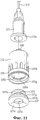
На фиг.10 представлен в разобранном виде одноразовый шприц, выполненный в соответствии со вторым вариантом выполнения данного изобретения.Figure 10 presents an exploded view of a disposable syringe made in accordance with the second embodiment of the present invention.
На фиг.11 представлен вид в аксонометрии основных элементов одноразового шприца, выполненного в соответствии со вторым вариантом выполнения данного изобретения.Figure 11 presents a perspective view of the main elements of a disposable syringe made in accordance with the second embodiment of the present invention.
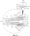
На фиг.12 представлен поперечный разрез основных элементов одноразового шприца, выполненного в соответствии со вторым вариантом выполнения данного изобретения.On Fig presents a cross section of the main elements of a disposable syringe made in accordance with the second embodiment of the present invention.
Лучшие варианты осуществления изобретенияThe best embodiments of the invention
Ниже подробно рассматриваются предпочтительные варианты выполнения данного изобретения, примеры которых проиллюстрированы на сопроводительных чертежах.Below are described in detail preferred embodiments of the present invention, examples of which are illustrated in the accompanying drawings.
Одноразовый шприц, выполненный в соответствии с первым вариантом выполнения данного изобретения, подробно описывается со ссылкой на фиг.6-8 и фиг.9A-9F.A disposable syringe made in accordance with a first embodiment of the present invention is described in detail with reference to FIGS. 6-8 and FIGS. 9A-9F.
Ниже приведено краткое описание предлагаемого одноразового шприца.The following is a brief description of the proposed disposable syringe.
С одной стороны цилиндра 101, оба конца которого открыты, вставлена переходная трубка 105. А в переходную трубку 105 введена вставная трубка 107 так, что находится в герметичном контакте с внутренней периферией цилиндра 101. В цилиндр 101 также вставлен шток с поршнем 104, предназначенным для приложения давления к инъекционной жидкости.On one side of the
Далее приведено описание каждой детали предлагаемого одноразового шприца.The following is a description of each part of the proposed disposable syringe.
Переходная трубка включает элемент 105f малого диаметра и элемент 105g большого диаметра, имеющий внутренний диаметр, превышающий диаметр элемента малого диаметра. Кроме того, вставная трубка имеет первый контактирующий элемент 107g, находящийся в герметичном контакте с внутренней периферией элемента большого диаметра переходной трубки, и вставной элемент 107f, вставленный в элемент малого диаметра. В дополнение к этому предпочтительней, чтобы у заднего конца первого контактирующего элемента был выполнен с расширением второй контактирующий элемент 107h, который находится в контакте с внутренней периферией цилиндра.The adapter tube includes a
Предпочтительней, чтобы на элементе малого диаметра переходной трубки был выполнен второй соединительный элемент 105а, а на вставном элементе вставной трубки был выполнен второй выступ 107b, соответствующий второму соединительному элементу переходной трубки. И предпочтительней, чтобы второй выступ вставной трубки был выполнен только на передней части вставной трубки. Кроме того предпочтительней, чтобы второй выступ вставной трубки был выполнен с наклоном к переднему концу вставной трубки. Предпочтительней, чтобы наружный диаметр первого контактирующего элемента вставной трубки превышал внутренний диаметр элемента большего диаметра переходной трубки, а по меньшей мере переходная трубка или вставная трубка была выполнена из упругого материала.Preferably, a second connecting
Предпочтительней, чтобы на внутренней периферии у заднего конца вставной трубки был выполнен первый соединительный элемент 107а, а у переднего конца поршня был выполнен первый выступ 112а, соответствующий первому соединительному элементу вставной трубки. Также предпочтительней, чтобы первый соединительный элемент вставной трубки или первый выступ поршня был выполнен с наклоном.It is preferable that the first connecting
Также предпочтительней, чтобы на внешней периферии переходной трубки был выполнен выступ 105b, а на внутренней периферии цилиндра был выполнен паз 101а, соответствующий выступу переходной трубки. В дополнение к этому предпочтительней, чтобы на внешней периферии переходной трубки был выполнен выступающий элемент 105с, а на внутренней периферии цилиндра был выполнен паз 101b для вставки, соответствующий выступающему элементу переходной трубки.It is also preferable that a
И предпочтительней, чтобы у переднего конца переходной трубки была выполнена с расширением трубка 106 для выпуска инъекционной жидкости, а с трубкой для выпуска инъекционной жидкости был соединен держатель 109 иглы шприца. Также предпочтительней, чтобы на переднем конце цилиндра была выполнена соединительная трубка 102, на внутренней периферии соединительной трубки был выполнен выступ 102а, а на держателе иглы шприца был выполнен фланец 109а, соответствующий выступу соединительной трубки.And it is preferable that at the front end of the adapter tube an
И наконец предпочтительней, чтобы у переднего конца поршня был эксцентрично выполнен создающий давление элемент 112, вставленный в трубку для выпуска инъекционной жидкости и выполненный из упругого материала.And finally, it is preferable that at the front end of the piston a pressure-generating
На фиг.6 представлен в разобранном виде одноразовый шприц, выполненный в соответствии с первым вариантом выполнения данного изобретения.Figure 6 presents an exploded view of a disposable syringe made in accordance with the first embodiment of the present invention.
В соответствии с фиг.6 предлагаемый шприц содержит цилиндр 101 с выполненной на нем соединительной трубкой 102, переходную трубку 105, вставленную внутрь цилиндра 101, и вставную трубку 107, вставленную в переходную трубку 105. Шприц также содержит шток 103 с поршнем 104 и выполненным на нем создающим давление элементом 112, а также держатель 109 иглы шприца, подсоединенный к соединительной трубке 102.In accordance with Fig. 6, the syringe according to the invention comprises a
Оба конца цилиндра 101 соединены друг с другом с образованием полого пространства внутри цилиндра. У переднего конца цилиндра 101 выполнена соединительная трубка 102, имеющая ступенчатый перепад. А у краевого участка внутренней периферии соединительной трубки 102 выполнен спиральный выступ 102а.Both ends of the
Переходная трубка 105 вставлена внутрь переднего конца цилиндра 101. На внешней поверхности переходной трубки 105 по ее внешней периферии выполнены крепежные выступы 105b, отстоящие друг от друга на определенное расстояние. Далее в центральной части переднего конца переходной трубки 105 выполнена трубка 106 для выпуска инъекционной жидкости, диаметр которой меньше диаметра переходной трубки 105.The
Вставная трубка 107 введена на определенную часть длины внутрь переходной трубки 105 так, что оказывает давление на переходную трубку 105 в направлении цилиндра 101, поддерживая тем самым условие герметичности между переходной трубкой 105 и цилиндром 101. На внешней периферии переднего конца вставной трубки 107 выполнен второй выступ 107b. Кроме того, на переднем крае вставной трубки 107 выполнена первая коническая наклонная поверхность 107с, имеющая наружный диаметр, уменьшающийся от заднего конца к переднему концу. Более того, на внешней периферии заднего конца вставной трубки 107 выполнена вторая коническая наклонная поверхность 107d, наружный диаметр которой уменьшается от заднего конца к переднему концу.The
На переднем конце штока 103 выполнен создающий давление элемент 112. Создающий давление элемент введен в трубку 106 для выпуска инъекционной жидкости, выполненную на переходной трубке 105. А на задней части создающего давление элемента 112 выполнен первый выступ 112а. Поршень 104 выполнен на переднем конце штока 103 так, что перемещается вдоль цилиндра 101 в герметичном контакте с внутренней поверхностью цилиндра 101, обеспечивая вследствие этого создание давления или всасывающего усилия. Кроме того, на штоке 103 около поршня 104 выполнена перерезающая канавка 111, которая позволяет легко переломить шток 103.A pressure-generating
На переднем конце держателя 109 иглы шприца закреплена игла 108 шприца, а на наружной поверхности заднего конца держателя 109 иглы шприца выполнен овальный фланец 109а. К держателю 109 иглы шприца прикреплен с возможностью отсоединения защитный колпачок 110, предназначенный для того, чтобы закрывать и защищать иглу 108 шприца.A
Фиг.7 подробно иллюстрирует внутреннюю конструкцию переходной трубки и вставной трубки одноразового шприца, выполненного в соответствии с первым вариантом данного изобретения.7 illustrates in detail the internal structure of the adapter tube and insertion tube of a disposable syringe made in accordance with the first embodiment of the present invention.
В соответствии с фиг.7 вдоль внутренней периферии вставной трубки 107 выполнен первый соединительный элемент 107а. Первый соединительный элемент 107а соединяется с первым выступом 112а, выполненным на создающем давление элементе 112. Другими словами, при вытягивании назад создающего давление элемента, выполненного на штоке, вставная трубка 107 также, соответственно, вытягивается назад. Кроме того, на заднем краю вставной трубки 107 выполнена наклонная поверхность 107е. Наклонная поверхность 107е идентична наклонной поверхности переднего конца поршня 104, что обеспечивает полное введение инъекционной жидкости и ее истечение. Вдоль внутренней периферии переходной трубки 105 выполнен второй соединительный элемент 105а. Второй соединительный элемент 105а соединяется со вторым выступом 107b, выполненным на вставной трубке 107. Другими словами, при перемещении вставной трубки 107 назад переходная трубка 105 также, соответственно, перемещается назад.In accordance with FIG. 7, a first connecting
Далее со ссылкой на фиг.6-8 приведено подробное описание процесса сборки одноразового шприца, выполненного в соответствии с первым вариантом выполнения данного изобретения.Next, with reference to Fig.6-8 is a detailed description of the Assembly process of a disposable syringe made in accordance with the first embodiment of the present invention.
В соответствии с фиг.6-8 трубка 106 для выпуска инъекционной жидкости, выполненная на переходной трубке 105, обращена к поверхности заднего конца цилиндра 101. И при перемещении переходной трубки 105 вперед она вводится и закрепляется внутри полого пространства цилиндра 101. На этой стадии крепежные выступы 105b, которые выполнены на внешней поверхности переходной трубки 105 по ее периферии и отстоят друг от друга на определенное расстояние, вводятся и закрепляются в крепежных пазах 101а, выполненных на внутренней периферии цилиндра 101.In accordance with Fig.6-8, the
После этого в полое пространство цилиндра 101 с его заднего конца вводят вставную трубку 107, которую затем проталкивают и перемещают вперед. В определенный момент вставная трубка 107 оказывается введенной и прикрепленной к внутренней периферии переходной трубки 105. Второй выступ 107b, расположенный на внешней периферии вставной трубки 107, соединяется со вторым соединительным элементом 105а, выполненным на внутренней периферии переходной трубки 105, результатом чего является первая посадка с натягом. Это вызвано тем, что в месте соединения наружный диаметр вставной трубки 107 превышает внутренний диаметр переходной трубки 105. После этого при дальнейшем проталкивании вставной трубки 107 вперед к переднему концу цилиндра 101 второй выступ 107b преодолевает препятствующее усилие, создаваемое вторым соединительным элементом 105а. Это обусловлено тем, что на переднем краю вставной трубки 107 выполнена первая коническая наклонная поверхность 107с, имеющая наружный диаметр, который уменьшается от заднего конца к переднему концу, а также тем, что вставная трубка 107 выполнена из упругого материала.After that, an
Между тем, по мере проталкивания вставной трубки 107 еще дальше к переднему концу цилиндра 101 возникает вторая посадка с натягом между внешней периферией заднего конца вставной трубки 107 и внутренней периферией заднего конца переходной трубки 105. Другими словами, вставная трубка 107 и переходная трубка 105 соединяются на посадке с натягом. Данное обстоятельство обусловлено тем, что наружный диаметр вставной трубки 107 несколько превышает внутренний диаметр заднего конца переходной трубки 105. Вставную трубку 107 проталкивают дальше до полного введения в переходную трубку 105. Это обусловлено тем, что на переднем краю вставной трубки 107 выполнена вторая коническая наклонная поверхность 107d с наружным диаметром, уменьшающимся от заднего конца к переднему концу, а также тем, что вставная трубка 107 выполнена из упругого материала.Meanwhile, as the
При полном введении вставной трубки 107 в переходную трубку 105 вставная трубка 107 оказывает давление на заднюю часть переходной трубки 105 в направлении цилиндра 101. Поэтому между переходной трубкой 105 и цилиндром 101 может поддерживаться условие герметичности. На этой стадии происходит прикрепление полукруглого выступающего элемента 105с, выполненного по периферии заднего конца переходной трубки 105, к полукруглому крепежному пазу 101b, выполненному на внутренней поверхности цилиндра 101. Следовательно, выступающий элемент 105с работает в качестве уплотняющего средства, увеличивающего состояние герметичности между переходной трубкой 105 и цилиндром 101, предотвращая тем самым просачивание инъекционной жидкости между переходной трубкой 105 и цилиндром 101 при любых возможных обстоятельствах.When the
Как описано выше, переходную трубку 105 вставляют в полое пространство цилиндра 101, а вставную трубку 107 вводят и прикрепляют к переходной трубке 105. Затем внутри полого пространства цилиндра 101 располагают поршень 104. И вводят в цилиндр 101 шток 103 с выполненной на нем перерезающей канавкой 111. После этого держатель 109 иглы шприца вводят и прикрепляют к трубке 106 для выпуска инъекционной жидкости, которую затем прикрепляют к соединительной трубке 102, выполненной в цилиндре 101.As described above, the
При введении держателя 109 иглы шприца в трубку 106 для выпуска инъекционной жидкости, выполненную в переходной трубке 105, держатель 109 иглы шприца может быть непосредственно введен в трубку 106 для выпуска инъекционной жидкости. Трубку 106 для выпуска инъекционной жидкости закрепляют в переходной трубке 105 на посадке с натягом. Поэтому инъекционная жидкость при ее введении не просачивается между трубкой 106 для выпуска инъекционной жидкости и держателем 109 иглы шприца. Кроме того, на внешней поверхности заднего конца держателя 109 иглы шприца выполнен овальный фланец 109а. Предпочтительней, чтобы овальный фланец 109а соединялся со спиральным выступом 102а, созданным в форме спирали на внутренней периферии соединительной трубки 102, выполненной на переднем конце цилиндра и имеющей ступенчатый перепад.By inserting the
Этап прикрепления держателя 109 иглы шприца, содержащего присоединенную к нему иглу 108 шприца, к трубке 106 для выпуска инъекционной жидкости, расположенной на переходной трубке 105, также может быть выполнен во время первого этапа сборки предлагаемого одноразового шприца. Однако поскольку этап сборки не ограничивается только одним способом, преимущество данного изобретения заключается в том, что описанный выше этап в альтернативном варианте может быть выполнен во время этапа процесса перед фактическим использованием одноразового шприца. И наконец, к держателю 109 иглы шприца прикрепляют защитный колпачок 110, защищающий иглу 108 шприца от внешнего контакта.The step of attaching the
Фиг.9А-9F представляют поперечные разрезы, показывающие этапы использования одноразового шприца, выполненного в соответствии с первым вариантом выполнения данного изобретения.9A-9F are cross-sectional views showing steps for using a disposable syringe in accordance with a first embodiment of the present invention.
Для введения инъекционной жидкости пациенту сначала необходимо заполнить полое пространство цилиндра инъекционной жидкостью. Однако этот этап идентичен этапу, описанному при рассмотрении известного уровня техники, и поэтому для упрощения не рассматривается. Фиг.9А иллюстрирует заполненный инъекционной жидкостью цилиндр, показанный слева от поршня 104, прикрепленного к штоку 103.To administer injection fluid, the patient must first fill the hollow space of the cylinder with injection fluid. However, this step is identical to the step described when considering the prior art, and therefore is not considered for simplification. Figa illustrates a cylinder filled with injection fluid, shown to the left of the
Этап введения инъекционной жидкости пациенту также идентичен этапу, описанному при рассмотрении известного уровня техники, и поэтому для упрощения не рассматривается. Однако в данном изобретении во время процесса введения благодаря вставной трубке 107 сохраняется условие герметичности между цилиндром 101 и переходной трубкой 105, которая прикреплена у переднего конца цилиндра 101. Следовательно, инъекционная жидкость, вытекающая из цилиндра 101, течет через трубку 106 для выпуска инъекционной жидкости, выполненную в переходной трубке 105, вынимаемой из шприца.The step of administering the injection fluid to the patient is also identical to the step described in the prior art, and therefore is not considered for simplification. However, in the present invention, during the insertion process, due to the
На фиг.8 и 9В проиллюстрировано завершение введения инъекционной жидкости пациенту.On Fig and 9B illustrates the completion of the injection of fluid to the patient.
В соответствии с фиг.8 и 9В наклонный выступающий элемент 104а поршня 104 точно входит в наклонный пустотелый элемент 107е вставной трубки 107. Другими словами, во время процесса введения, при приложении давления к внутренней периферии цилиндра 101 инъекционная жидкость внутри цилиндра 101 естественным образом стекает вниз к центру вдоль наклонного пустотелого элемента 107е вставной трубки 107. Затем инъекционная жидкость легко перетекает через вставную трубку 107, выдавливаясь из цилиндра 101 без остатка.In accordance with FIGS. 8 and 9B, the inclined protruding
Между тем, создающий давление элемент 112, выполненный в центральной части у переднего конца штока 103, через внутреннюю периферию вставной трубки 107 входит во внутреннюю периферию трубки 106 для выпуска инъекционной жидкости переходной трубки 105 и прикрепляется к ней. Затем край наклонного горизонтального центрального острого конца создающего давление элемента 112 нажимает на определенный участок трубки 106 для выпуска инъекционной жидкости. Другими словами, создающий давление элемент 112 оказывает эксцентричное давление на определенную контактную точку трубки 108 для выпуска инъекционной жидкости.Meanwhile, the pressure-generating
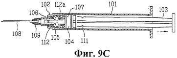
Фиг.9С иллюстрирует этап снятия состояния герметичности между цилиндром и переходной трубкой.Fig. 9C illustrates the step of removing a leak condition between a cylinder and a transition tube.
В соответствии с фиг.9С после завершения введения пользователь вытягивает цилиндр 101 в направлении, противоположном пациенту для того, чтобы вытащить иглу 108 шприца из кожи пациента. Затем, за счет вытягивания штока 103 назад к заднему концу цилиндра 101, создающий давление элемент 112, выполненный на штоке 103, также вытягивается назад. Первый выступ 112а, выполненный на внешней периферии создающего давление элемента 112, соединяется с первым соединительным элементом 107а, выполненным по внутренней периферии вставной трубки 107. Следовательно, тяговое усилие, приложенное к заднему концу штока 103, через первый выступ 112а передается к вставной трубке 107, давая тем самым возможность вставной трубке 107 слегка сместиться наружу из внутренней периферии переходной трубки 105. Другими словами, перемещение допускается в пределах зазора между внутренней периферией переходной трубки и внешней периферией вставной трубки. Поэтому снимается оказываемое вставной трубкой 107 давление от переходной трубки 105 к цилиндру 101, и в соответствии с этим также исчезает герметичный контакт между переходной трубкой 105 и цилиндром 101. Однако при отсутствии зазора между внутренней периферией переходной трубки 105 и внешней периферией вставной трубки 107, состояние герметичности между переходной трубкой 105 и цилиндром 101 не может быть легко снято. Это обусловлено трением по всей поверхности соприкосновения цилиндра 101 и переходной трубки 105 при оттягивании штока назад. Однако поскольку в данном изобретении между переходной трубкой 105 и вставной трубкой 107 выполнен зазор, то для снятия состояния герметичности требуется усилие, достаточное для преодоления трения между переходной трубкой 105 и вставной трубкой 107. Если говорить более конкретно, то переходная трубка 105 и вставная трубка 107 имеют относительно небольшую поверхность контакта. Поэтому, даже несмотря на то, что соединение двух элементов друг с другом выполнено на посадке с натягом, состояние герметичности между цилиндром 101 и переходной трубкой 105 может быть легко снято.In accordance with figs after completion of the introduction, the user pulls the
Между тем, соединительный элемент может быть выполнен вдоль внутренней периферии трубки 106 для выпуска инъекционной жидкости, контактирующей с краем создающего давление элемента 112, а выступ может быть выполнен у края создающего давление элемента 112 ближе к его переднему концу по сравнению с соединительным элементом. Поэтому в рассматриваемом далее процессе, когда шток 103 оттягивается назад и перемещается назад вместе с создающим давление элементом 112, выступ соединен с соединительным элементом, прикладывая тем самым к трубке 106 для выпуска инъекционной жидкости тяговое усилие в направлении заднего конца шприца.Meanwhile, the connecting member may be formed along the inner periphery of the injection
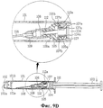
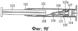
Фиг.9D иллюстрирует этап втягивания держателя иглы шприца внутрь цилиндра.Fig. 9D illustrates the step of retracting the syringe needle holder into the cylinder.
В соответствии с фиг.9D, после снятия состояния герметичности между цилиндром 101 и переходной трубкой 105, трение между цилиндром и переходной трубкой значительно уменьшается. Поэтому при оттягивании штока 103 назад держатель 109 иглы шприца может быть легко введен внутрь цилиндра 101. Далее приводится более подробное описание данного процесса. При отведении вставной трубки 107 назад второй выступ 107b, выполненный на внешней периферии вставной трубки 107, соединяется со вторым соединительным элементом 105а, выполненным во внутренней периферии переходной трубки 105. Следовательно, вставная трубка 107 во время перемещения вытягивает переходную трубку 105, перемещаясь к заднему концу цилиндра 101. На этой стадии поскольку держатель 109 иглы шприца прикреплен к трубке 106 для выпуска инъекционной жидкости, выполненной на переходной трубке 105, держатель 109 иглы шприца также втягивается в полое пространство цилиндра 101. Другими словами, в полое пространство цилиндра 101 втягивается игла 108 шприца, поскольку она прикреплена к держателю 109 иглы шприца.In accordance with fig.9D, after removing the tightness between the
При втягивании держателя 109 иглы шприца в полое пространство цилиндра 101 задний конец переходной трубки 105 отстоит от края цилиндра 101. При этом переходная трубка 105 и держатель 109 иглы шприца, вставленный в трубку 106 для выпуска инъекционной жидкости, оказываются подвешенными на наружном краю вставной трубки 107, вставленной в переходную трубку 105. На этой стадии из-за эксцентричности центра тяжести передний конец переходной трубки 105, присоединенный к держателю 109 иглы шприца, наклонен вниз (т.е. в направлении действия силы тяжести).When the
Кроме того, благодаря создающему давление элементу 112, выполненному на краю штока 103, на переходную трубку 105, присоединенную к держателю 109 иглы шприца, оказывается давление в направлении действия силы тяжести. Как описано выше, после завершения процесса введения край создающего давление элемента 112, имеющий наклонный горизонтальный заостренный конец, нажимает на определенную контактную точку трубки 106 для выпуска инъекционной жидкости. После этого, поскольку создающий давление элемент 112 выполнен из упругого материала, то при вытягивании штока 103 назад в направлении действия силы тяжести действует сила упругой деформации, оказывающая давление на соединенное тело. Здесь прикладывается усилие, так как первый выступ 112а, выполненный на внешней периферии создающего давление элемента 112 соединен с первым соединительным элементом 107а. Усилие, приложенное к первому выступу 112а, также передается к создающему давление элементу 112, прижимая тем самым соединенное тело вниз (т.е. в направлении действия силы тяжести). Поэтому переходная трубка 105, присоединенная к держателю 109 иглы шприца, наклоняется вниз, так как соединенное тело подвешено на наружном краю вставной трубки 107. Если говорить более конкретно, то только передний конец иглы 108 шприца, прикрепленной к держателю 109 иглы шприца, входит в контакт с внутренней поверхностью цилиндра 101. Поэтому между контактной поверхностью цилиндра 101 и иглой 108 шприца, прикрепленной к держателю 109 иглы шприца, сохраняется постоянный угол наклона.In addition, due to the pressure-generating
Фиг.9Е и 9F иллюстрируют этапы предотвращения вытягивания держателя иглы шприца из цилиндра. Однако эти этапы аналогичны этапам, известным для одноразовых шприцов из уровня техники, поэтому для упрощения их описание не приводится.9E and 9F illustrate the steps of preventing the syringe needle holder from being pulled out of the cylinder. However, these steps are similar to those known for prior art disposable syringes; therefore, a description thereof is not provided for simplicity.
Далее со ссылкой на фиг.10-12 приводится подробное описание одноразового шприца, выполненного в соответствии со вторым вариантом выполнения данного изобретения.Next, with reference to FIGS. 10-12, a detailed description of a disposable syringe made in accordance with a second embodiment of the present invention is given.
На фиг.10 представлен в разобранном виде одноразовый шприц, выполненный в соответствии со вторым вариантом данного изобретения. На фиг.11 представлен аксонометрический вид основных элементов одноразового шприца, выполненного в соответствии со вторым вариантом данного изобретения. На фиг.12 представлены поперечные разрезы основных элементов одноразового шприца, выполненного в соответствии со вторым вариантом данного изобретения.Figure 10 presents an exploded view of a disposable syringe made in accordance with the second embodiment of the present invention. Figure 11 presents a perspective view of the main elements of a disposable syringe made in accordance with the second embodiment of the present invention. On Fig presents cross-sectional views of the main elements of a disposable syringe made in accordance with the second variant of the present invention.
В соответствии с фиг.10 одноразовый шприц, выполненный в соответствии со вторым вариантом данного изобретения, содержит цилиндр 101, оба конца которого открыты, переходную трубку 105, вставленную внутрь цилиндра 101, и вставную трубку 107, вставленную в переходную трубку 105. Одноразовый шприц также содержит поршень 104, шток 103 с создающим давление элементом 112, выполненным на его краю, а также держатель 109 иглы шприца, прикрепленный к соединительной трубке 102.In accordance with FIG. 10, a disposable syringe made in accordance with a second embodiment of the present invention comprises a
В отличие от первого варианта выполнения данного изобретения в одноразовом шприце, выполненном в соответствии со вторым вариантом данного изобретения, соединительная трубка 102 с прикрепленным к ней держателем 109 иглы шприца выполнена не на цилиндре 101, а непосредственно на переходной трубке 105. Другими словами, отличие от первого варианта выполнения изобретения заключается только в конструкциях цилиндра 101 и переходной трубки 105. Следовательно, этапы использования одноразового шприца и этапы сборки аналогичны описанным в первом варианте выполнения, поэтому описание второго варианта выполнения для упрощения не приводится.Unlike the first embodiment of the present invention, in a disposable syringe made in accordance with the second embodiment of the present invention, the connecting
Для специалистов в данной области техники очевидно, что возможны различные модификации и варианты данного изобретения, не выходящие за пределы сущности или объема правовой охраны изобретения. Таким образом, подразумевается, что данное изобретение охватывает все модификации и варианты этого изобретения при условии, что они находятся в пределах объема правовой охраны пунктов прилагаемой формулы изобретения и их эквивалентов.For specialists in the art it is obvious that various modifications and variations of the present invention are possible, without going beyond the essence or scope of legal protection of the invention. Thus, it is intended that this invention covers all modifications and variations of this invention provided that they fall within the scope of legal protection of the appended claims and their equivalents.
Промышленная применимостьIndustrial applicability
В данном изобретении предлагается шприц, содержащий переходную трубку и вставную трубку, которые с трудом деформируются при приложении к ним внешнего давления. Кроме того, переходная трубка и вставная трубка точно размещены внутри цилиндра шприца, обеспечивая стабильность процесса сборки и тем самым снижая дефектность продукции.The present invention provides a syringe containing an adapter tube and an insertion tube that are difficult to deform when external pressure is applied thereto. In addition, the adapter tube and insertion tube are precisely positioned inside the syringe barrel, ensuring stability of the assembly process and thereby reducing product defectiveness.
Кроме того, отсутствие необходимости в производственной линии во вспомогательных промышленных устройствах, предназначенных для уменьшения дефектности одноразовых шприцов, снижает стоимость производства.In addition, the lack of need for a production line in auxiliary industrial devices designed to reduce the defectiveness of disposable syringes reduces the cost of production.
И наконец, дефектность переходной трубки и вставной трубки, при ее наличии, может быть легко определена невооруженным глазом во время процесса сборки одноразового шприца. Поэтому в неповрежденном состоянии исключено просачивание инъекционной жидкости из одноразового шприца, вследствие чего повышается надежность изделия.Finally, the defectiveness of the adapter tube and insertion tube, if present, can be easily determined with the naked eye during the assembly process of the disposable syringe. Therefore, in an intact state, leakage of injection liquid from a disposable syringe is excluded, thereby increasing the reliability of the product.
Claims (16)
Applications Claiming Priority (4)
| Application Number | Priority Date | Filing Date | Title |
|---|---|---|---|
| KR10-2003-0033400 | 2003-05-26 | ||
| KR1020030033400 | 2003-05-26 | ||
| KR10-2004-0014356 | 2004-03-03 | ||
| KR1020040014356A KR100566568B1 (en) | 2003-05-26 | 2004-03-03 | disposable safety syringe |
Publications (2)
| Publication Number | Publication Date |
|---|---|
| RU2005136445A RU2005136445A (en) | 2006-06-10 |
| RU2314130C2 true RU2314130C2 (en) | 2008-01-10 |
Family
ID=36461860
Family Applications (1)
| Application Number | Title | Priority Date | Filing Date |
|---|---|---|---|
| RU2005136445/14A RU2314130C2 (en) | 2003-05-26 | 2004-05-25 | Disposable syringe |
Country Status (13)
| Country | Link |
|---|---|
| US (1) | US7686784B2 (en) |
| EP (1) | EP1626761B1 (en) |
| JP (1) | JP4308249B2 (en) |
| CN (1) | CN100448495C (en) |
| AU (1) | AU2004241880B2 (en) |
| BR (1) | BRPI0410658B8 (en) |
| CA (1) | CA2526983C (en) |
| DE (1) | DE602004022802D1 (en) |
| EG (1) | EG24302A (en) |
| ES (1) | ES2332513T3 (en) |
| MX (1) | MXPA05012782A (en) |
| RU (1) | RU2314130C2 (en) |
| WO (1) | WO2004103429A2 (en) |
Cited By (1)
| Publication number | Priority date | Publication date | Assignee | Title |
|---|---|---|---|---|
| RU2763787C2 (en) * | 2013-10-24 | 2022-01-11 | Астразенека Аб | Stable aqueous compositions based on antibodies |
Families Citing this family (21)
| Publication number | Priority date | Publication date | Assignee | Title |
|---|---|---|---|---|
| US7371226B2 (en) * | 2005-06-27 | 2008-05-13 | Hung Chi Huang | Plunger of a syringe |
| GB0608046D0 (en) | 2006-04-25 | 2006-05-31 | Star Syringe Ltd | Syringe |
| US20080097303A1 (en) * | 2006-06-02 | 2008-04-24 | Chih-Hsiung Chen | Syringe with retractable needle |
| JP4994775B2 (en) | 2006-10-12 | 2012-08-08 | 日本コヴィディエン株式会社 | Needle point protector |
| US7803134B2 (en) | 2007-01-10 | 2010-09-28 | Animas Corporation | Syringe assembly and infusion pump assembly incorporating such |
| AU2007352135B2 (en) * | 2007-04-24 | 2011-09-29 | Morgan Meditech Inc | Single use syringe |
| JP2009240411A (en) * | 2008-03-28 | 2009-10-22 | Terumo Corp | Drug container |
| EP3865162B1 (en) * | 2009-07-10 | 2024-02-28 | Becton, Dickinson and Company | Flush syringe assembly |
| KR200458761Y1 (en) * | 2009-07-20 | 2012-03-07 | 방영철 | Syringe with re-use prevention feature |
| US20110139650A1 (en) * | 2009-12-15 | 2011-06-16 | Amcor Flexibles, Inc. | Sterilizable Package Having Breathable Membrane for the Packaging of Medical Devices |
| EP2374503B1 (en) | 2010-04-08 | 2012-07-11 | Sorin CRM SAS | Active implantable medical device for vagal stimulation with optimised ventricular filling |
| US8486024B2 (en) | 2011-04-27 | 2013-07-16 | Covidien Lp | Safety IV catheter assemblies |
| WO2013048768A1 (en) | 2011-09-26 | 2013-04-04 | Covidien Lp | Safety iv catheter and needle assembly |
| EP2760520A1 (en) | 2011-09-26 | 2014-08-06 | Covidien LP | Safety catheter |
| US8834422B2 (en) | 2011-10-14 | 2014-09-16 | Covidien Lp | Vascular access assembly and safety device |
| CN102836482B (en) * | 2012-09-10 | 2014-03-05 | 苏州市雅思精密模具有限公司 | Disposable injector and manufacturing technology thereof |
| KR102023143B1 (en) * | 2012-11-08 | 2019-09-19 | 술저 믹스팩 아게 | Cartridge for at least two flowable components |
| US11083847B2 (en) | 2018-01-26 | 2021-08-10 | Becton, Dickinson And Company | Flush syringe with flip cap |
| CN110876824A (en) * | 2018-09-06 | 2020-03-13 | 广东海鸥医疗器械股份有限公司 | Syringe |
| US11187700B1 (en) * | 2021-01-28 | 2021-11-30 | Eckhard Kemmann | Closed system for enlarging viral and bacterial particles for identification by diffraction scanning |
| CN113509614A (en) * | 2021-08-19 | 2021-10-19 | 尹建明 | Syringe piston and syringe |
Family Cites Families (6)
| Publication number | Priority date | Publication date | Assignee | Title |
|---|---|---|---|---|
| MY104360A (en) * | 1987-12-30 | 1994-03-31 | Verlier Jacques | Non-reusable syringe |
| US5171300A (en) * | 1988-02-01 | 1992-12-15 | Medtech Group, Inc. | Disposable hypodermic syringe |
| CN2064236U (en) * | 1990-05-03 | 1990-10-24 | 洪流 | Disposable injector for medical purpose |
| CN2183783Y (en) * | 1994-02-08 | 1994-11-30 | 韩九林 | Disposable self-damaging injector |
| US6391008B1 (en) * | 2000-08-15 | 2002-05-21 | Hsi-Chin Tsai | Safety hypodermic syringe |
| US6488657B1 (en) * | 2001-09-21 | 2002-12-03 | M.K. Meditech Co., Ltd. | Needle holder positioning structure for safety hypodermic syringe |
-
2004
- 2004-05-25 CN CNB200480014621XA patent/CN100448495C/en active Active
- 2004-05-25 BR BRPI0410658A patent/BRPI0410658B8/en not_active IP Right Cessation
- 2004-05-25 EP EP04734772A patent/EP1626761B1/en active Active
- 2004-05-25 JP JP2006502724A patent/JP4308249B2/en active Active
- 2004-05-25 CA CA2526983A patent/CA2526983C/en active Active
- 2004-05-25 RU RU2005136445/14A patent/RU2314130C2/en active
- 2004-05-25 DE DE602004022802T patent/DE602004022802D1/en active Active
- 2004-05-25 AU AU2004241880A patent/AU2004241880B2/en not_active Ceased
- 2004-05-25 US US10/499,181 patent/US7686784B2/en active Active
- 2004-05-25 ES ES04734772T patent/ES2332513T3/en active Active
- 2004-05-25 MX MXPA05012782A patent/MXPA05012782A/en active IP Right Grant
- 2004-05-25 WO PCT/KR2004/001241 patent/WO2004103429A2/en active IP Right Grant
-
2005
- 2005-11-23 EG EGNA2005000759 patent/EG24302A/en active
Cited By (1)
| Publication number | Priority date | Publication date | Assignee | Title |
|---|---|---|---|---|
| RU2763787C2 (en) * | 2013-10-24 | 2022-01-11 | Астразенека Аб | Stable aqueous compositions based on antibodies |
Also Published As
| Publication number | Publication date |
|---|---|
| EG24302A (en) | 2009-01-12 |
| EP1626761A2 (en) | 2006-02-22 |
| RU2005136445A (en) | 2006-06-10 |
| EP1626761B1 (en) | 2009-08-26 |
| BRPI0410658A (en) | 2006-06-20 |
| AU2004241880B2 (en) | 2007-07-19 |
| ES2332513T3 (en) | 2010-02-08 |
| US20060111668A1 (en) | 2006-05-25 |
| WO2004103429A2 (en) | 2004-12-02 |
| JP2006525830A (en) | 2006-11-16 |
| CN100448495C (en) | 2009-01-07 |
| WO2004103429A3 (en) | 2005-06-09 |
| BRPI0410658B1 (en) | 2015-10-20 |
| CA2526983A1 (en) | 2004-12-02 |
| JP4308249B2 (en) | 2009-08-05 |
| US7686784B2 (en) | 2010-03-30 |
| CN1795021A (en) | 2006-06-28 |
| DE602004022802D1 (en) | 2009-10-08 |
| CA2526983C (en) | 2010-08-10 |
| MXPA05012782A (en) | 2006-05-17 |
| BRPI0410658B8 (en) | 2021-06-22 |
| AU2004241880A1 (en) | 2004-12-02 |
Similar Documents
| Publication | Publication Date | Title |
|---|---|---|
| RU2314130C2 (en) | Disposable syringe | |
| AU2002350451B2 (en) | Spring launched needle safety clip | |
| US6681810B2 (en) | Filling device for a needleless injector cartridge | |
| AU2010202200B2 (en) | Single use syringe having safety shield | |
| US6632198B2 (en) | Retracting needle syringe | |
| US6221052B1 (en) | Retracting needle syringe | |
| KR20090036565A (en) | A single use syringe | |
| JP2001524013A (en) | Disposable needle mounting hub | |
| KR200350792Y1 (en) | disposable safety syringe | |
| JP2004504890A (en) | Needleless syringe that works by compressing the chemical storage reservoir | |
| KR100660317B1 (en) | Disposable safety syringe | |
| KR100547617B1 (en) | disposable safety syringe | |
| KR200323883Y1 (en) | disposable safety syringe | |
| KR100506701B1 (en) | disposable safety syringe | |
| KR100473371B1 (en) | disposable safety syringe | |
| KR200327191Y1 (en) | disposable safety syringe | |
| KR200338196Y1 (en) | disposable safety syringe | |
| KR200320327Y1 (en) | disposable safety syringe | |
| KR200327275Y1 (en) | disposable safety syringe | |
| KR200320342Y1 (en) | disposable safety syringe | |
| KR200317776Y1 (en) | disposable safety syringe | |
| KR200311386Y1 (en) | disposable safety syringe | |
| KR200314465Y1 (en) | disposable safety syringe | |
| US20140163518A1 (en) | Safety Syringe | |
| KR20040108477A (en) | disposable safety syringe |