RU2313740C2 - Method and device for product cooling, particularly for gas liquefaction - Google Patents

Method and device for product cooling, particularly for gas liquefaction Download PDF

Info

Publication number
RU2313740C2
RU2313740C2 RU2005141485/06A RU2005141485A RU2313740C2 RU 2313740 C2 RU2313740 C2 RU 2313740C2 RU 2005141485/06 A RU2005141485/06 A RU 2005141485/06A RU 2005141485 A RU2005141485 A RU 2005141485A RU 2313740 C2 RU2313740 C2 RU 2313740C2
Authority
RU
Russia
Prior art keywords
refrigerant
adsorption
cycle
evaporator
heat
Prior art date
Application number
RU2005141485/06A
Other languages
Russian (ru)
Other versions
RU2005141485A (en
Inventor
Пьер МИХАЛЬСКИЙ (FR)
Пьер МИХАЛЬСКИЙ
Пьер ГУРМЕЛЕН (FR)
Пьер ГУРМЕЛЕН
Клод БЛЭЗА (FR)
Клод БЛЭЗА
Original Assignee
Газ Транспор Э Текнигаз
Priority date (The priority date is an assumption and is not a legal conclusion. Google has not performed a legal analysis and makes no representation as to the accuracy of the date listed.)
Filing date
Publication date
Application filed by Газ Транспор Э Текнигаз filed Critical Газ Транспор Э Текнигаз
Publication of RU2005141485A publication Critical patent/RU2005141485A/en
Application granted granted Critical
Publication of RU2313740C2 publication Critical patent/RU2313740C2/en

Links

Images

Classifications

    • FMECHANICAL ENGINEERING; LIGHTING; HEATING; WEAPONS; BLASTING
    • F25REFRIGERATION OR COOLING; COMBINED HEATING AND REFRIGERATION SYSTEMS; HEAT PUMP SYSTEMS; MANUFACTURE OR STORAGE OF ICE; LIQUEFACTION SOLIDIFICATION OF GASES
    • F25BREFRIGERATION MACHINES, PLANTS OR SYSTEMS; COMBINED HEATING AND REFRIGERATION SYSTEMS; HEAT PUMP SYSTEMS
    • F25B17/00Sorption machines, plants or systems, operating intermittently, e.g. absorption or adsorption type
    • F25B17/08Sorption machines, plants or systems, operating intermittently, e.g. absorption or adsorption type the absorbent or adsorbent being a solid, e.g. salt
    • F25B17/086Sorption machines, plants or systems, operating intermittently, e.g. absorption or adsorption type the absorbent or adsorbent being a solid, e.g. salt with two or more boiler-sorber/evaporator units
    • FMECHANICAL ENGINEERING; LIGHTING; HEATING; WEAPONS; BLASTING
    • F25REFRIGERATION OR COOLING; COMBINED HEATING AND REFRIGERATION SYSTEMS; HEAT PUMP SYSTEMS; MANUFACTURE OR STORAGE OF ICE; LIQUEFACTION SOLIDIFICATION OF GASES
    • F25BREFRIGERATION MACHINES, PLANTS OR SYSTEMS; COMBINED HEATING AND REFRIGERATION SYSTEMS; HEAT PUMP SYSTEMS
    • F25B17/00Sorption machines, plants or systems, operating intermittently, e.g. absorption or adsorption type
    • F25B17/08Sorption machines, plants or systems, operating intermittently, e.g. absorption or adsorption type the absorbent or adsorbent being a solid, e.g. salt
    • FMECHANICAL ENGINEERING; LIGHTING; HEATING; WEAPONS; BLASTING
    • F25REFRIGERATION OR COOLING; COMBINED HEATING AND REFRIGERATION SYSTEMS; HEAT PUMP SYSTEMS; MANUFACTURE OR STORAGE OF ICE; LIQUEFACTION SOLIDIFICATION OF GASES
    • F25BREFRIGERATION MACHINES, PLANTS OR SYSTEMS; COMBINED HEATING AND REFRIGERATION SYSTEMS; HEAT PUMP SYSTEMS
    • F25B17/00Sorption machines, plants or systems, operating intermittently, e.g. absorption or adsorption type
    • FMECHANICAL ENGINEERING; LIGHTING; HEATING; WEAPONS; BLASTING
    • F25REFRIGERATION OR COOLING; COMBINED HEATING AND REFRIGERATION SYSTEMS; HEAT PUMP SYSTEMS; MANUFACTURE OR STORAGE OF ICE; LIQUEFACTION SOLIDIFICATION OF GASES
    • F25JLIQUEFACTION, SOLIDIFICATION OR SEPARATION OF GASES OR GASEOUS OR LIQUEFIED GASEOUS MIXTURES BY PRESSURE AND COLD TREATMENT OR BY BRINGING THEM INTO THE SUPERCRITICAL STATE
    • F25J1/00Processes or apparatus for liquefying or solidifying gases or gaseous mixtures
    • F25J1/0002Processes or apparatus for liquefying or solidifying gases or gaseous mixtures characterised by the fluid to be liquefied
    • F25J1/0005Light or noble gases
    • F25J1/001Hydrogen
    • FMECHANICAL ENGINEERING; LIGHTING; HEATING; WEAPONS; BLASTING
    • F25REFRIGERATION OR COOLING; COMBINED HEATING AND REFRIGERATION SYSTEMS; HEAT PUMP SYSTEMS; MANUFACTURE OR STORAGE OF ICE; LIQUEFACTION SOLIDIFICATION OF GASES
    • F25JLIQUEFACTION, SOLIDIFICATION OR SEPARATION OF GASES OR GASEOUS OR LIQUEFIED GASEOUS MIXTURES BY PRESSURE AND COLD TREATMENT OR BY BRINGING THEM INTO THE SUPERCRITICAL STATE
    • F25J1/00Processes or apparatus for liquefying or solidifying gases or gaseous mixtures
    • F25J1/0002Processes or apparatus for liquefying or solidifying gases or gaseous mixtures characterised by the fluid to be liquefied
    • F25J1/0022Hydrocarbons, e.g. natural gas
    • F25J1/0025Boil-off gases "BOG" from storages
    • FMECHANICAL ENGINEERING; LIGHTING; HEATING; WEAPONS; BLASTING
    • F25REFRIGERATION OR COOLING; COMBINED HEATING AND REFRIGERATION SYSTEMS; HEAT PUMP SYSTEMS; MANUFACTURE OR STORAGE OF ICE; LIQUEFACTION SOLIDIFICATION OF GASES
    • F25JLIQUEFACTION, SOLIDIFICATION OR SEPARATION OF GASES OR GASEOUS OR LIQUEFIED GASEOUS MIXTURES BY PRESSURE AND COLD TREATMENT OR BY BRINGING THEM INTO THE SUPERCRITICAL STATE
    • F25J1/00Processes or apparatus for liquefying or solidifying gases or gaseous mixtures
    • F25J1/02Processes or apparatus for liquefying or solidifying gases or gaseous mixtures requiring the use of refrigeration, e.g. of helium or hydrogen ; Details and kind of the refrigeration system used; Integration with other units or processes; Controlling aspects of the process
    • F25J1/0225Processes or apparatus for liquefying or solidifying gases or gaseous mixtures requiring the use of refrigeration, e.g. of helium or hydrogen ; Details and kind of the refrigeration system used; Integration with other units or processes; Controlling aspects of the process using other external refrigeration means not provided before, e.g. heat driven absorption chillers
    • FMECHANICAL ENGINEERING; LIGHTING; HEATING; WEAPONS; BLASTING
    • F25REFRIGERATION OR COOLING; COMBINED HEATING AND REFRIGERATION SYSTEMS; HEAT PUMP SYSTEMS; MANUFACTURE OR STORAGE OF ICE; LIQUEFACTION SOLIDIFICATION OF GASES
    • F25JLIQUEFACTION, SOLIDIFICATION OR SEPARATION OF GASES OR GASEOUS OR LIQUEFIED GASEOUS MIXTURES BY PRESSURE AND COLD TREATMENT OR BY BRINGING THEM INTO THE SUPERCRITICAL STATE
    • F25J1/00Processes or apparatus for liquefying or solidifying gases or gaseous mixtures
    • F25J1/02Processes or apparatus for liquefying or solidifying gases or gaseous mixtures requiring the use of refrigeration, e.g. of helium or hydrogen ; Details and kind of the refrigeration system used; Integration with other units or processes; Controlling aspects of the process
    • F25J1/0243Start-up or control of the process; Details of the apparatus used; Details of the refrigerant compression system used
    • F25J1/0257Construction and layout of liquefaction equipments, e.g. valves, machines
    • F25J1/0262Details of the cold heat exchange system
    • F25J1/0264Arrangement of heat exchanger cores in parallel with different functions, e.g. different cooling streams
    • F25J1/0265Arrangement of heat exchanger cores in parallel with different functions, e.g. different cooling streams comprising cores associated exclusively with the cooling of a refrigerant stream, e.g. for auto-refrigeration or economizer
    • F25J1/0268Arrangement of heat exchanger cores in parallel with different functions, e.g. different cooling streams comprising cores associated exclusively with the cooling of a refrigerant stream, e.g. for auto-refrigeration or economizer using a dedicated refrigeration means
    • FMECHANICAL ENGINEERING; LIGHTING; HEATING; WEAPONS; BLASTING
    • F25REFRIGERATION OR COOLING; COMBINED HEATING AND REFRIGERATION SYSTEMS; HEAT PUMP SYSTEMS; MANUFACTURE OR STORAGE OF ICE; LIQUEFACTION SOLIDIFICATION OF GASES
    • F25JLIQUEFACTION, SOLIDIFICATION OR SEPARATION OF GASES OR GASEOUS OR LIQUEFIED GASEOUS MIXTURES BY PRESSURE AND COLD TREATMENT OR BY BRINGING THEM INTO THE SUPERCRITICAL STATE
    • F25J2210/00Processes characterised by the type or other details of the feed stream
    • F25J2210/90Boil-off gas from storage
    • FMECHANICAL ENGINEERING; LIGHTING; HEATING; WEAPONS; BLASTING
    • F25REFRIGERATION OR COOLING; COMBINED HEATING AND REFRIGERATION SYSTEMS; HEAT PUMP SYSTEMS; MANUFACTURE OR STORAGE OF ICE; LIQUEFACTION SOLIDIFICATION OF GASES
    • F25JLIQUEFACTION, SOLIDIFICATION OR SEPARATION OF GASES OR GASEOUS OR LIQUEFIED GASEOUS MIXTURES BY PRESSURE AND COLD TREATMENT OR BY BRINGING THEM INTO THE SUPERCRITICAL STATE
    • F25J2245/00Processes or apparatus involving steps for recycling of process streams
    • F25J2245/90Processes or apparatus involving steps for recycling of process streams the recycled stream being boil-off gas from storage
    • FMECHANICAL ENGINEERING; LIGHTING; HEATING; WEAPONS; BLASTING
    • F25REFRIGERATION OR COOLING; COMBINED HEATING AND REFRIGERATION SYSTEMS; HEAT PUMP SYSTEMS; MANUFACTURE OR STORAGE OF ICE; LIQUEFACTION SOLIDIFICATION OF GASES
    • F25JLIQUEFACTION, SOLIDIFICATION OR SEPARATION OF GASES OR GASEOUS OR LIQUEFIED GASEOUS MIXTURES BY PRESSURE AND COLD TREATMENT OR BY BRINGING THEM INTO THE SUPERCRITICAL STATE
    • F25J2270/00Refrigeration techniques used
    • F25J2270/90External refrigeration, e.g. conventional closed-loop mechanical refrigeration unit using Freon or NH3, unspecified external refrigeration
    • F25J2270/906External refrigeration, e.g. conventional closed-loop mechanical refrigeration unit using Freon or NH3, unspecified external refrigeration by heat driven absorption chillers
    • FMECHANICAL ENGINEERING; LIGHTING; HEATING; WEAPONS; BLASTING
    • F25REFRIGERATION OR COOLING; COMBINED HEATING AND REFRIGERATION SYSTEMS; HEAT PUMP SYSTEMS; MANUFACTURE OR STORAGE OF ICE; LIQUEFACTION SOLIDIFICATION OF GASES
    • F25JLIQUEFACTION, SOLIDIFICATION OR SEPARATION OF GASES OR GASEOUS OR LIQUEFIED GASEOUS MIXTURES BY PRESSURE AND COLD TREATMENT OR BY BRINGING THEM INTO THE SUPERCRITICAL STATE
    • F25J2270/00Refrigeration techniques used
    • F25J2270/90External refrigeration, e.g. conventional closed-loop mechanical refrigeration unit using Freon or NH3, unspecified external refrigeration
    • F25J2270/908External refrigeration, e.g. conventional closed-loop mechanical refrigeration unit using Freon or NH3, unspecified external refrigeration by regenerative chillers, i.e. oscillating or dynamic systems, e.g. Stirling refrigerator, thermoelectric ("Peltier") or magnetic refrigeration
    • FMECHANICAL ENGINEERING; LIGHTING; HEATING; WEAPONS; BLASTING
    • F25REFRIGERATION OR COOLING; COMBINED HEATING AND REFRIGERATION SYSTEMS; HEAT PUMP SYSTEMS; MANUFACTURE OR STORAGE OF ICE; LIQUEFACTION SOLIDIFICATION OF GASES
    • F25JLIQUEFACTION, SOLIDIFICATION OR SEPARATION OF GASES OR GASEOUS OR LIQUEFIED GASEOUS MIXTURES BY PRESSURE AND COLD TREATMENT OR BY BRINGING THEM INTO THE SUPERCRITICAL STATE
    • F25J2290/00Other details not covered by groups F25J2200/00 - F25J2280/00
    • F25J2290/34Details about subcooling of liquids
    • FMECHANICAL ENGINEERING; LIGHTING; HEATING; WEAPONS; BLASTING
    • F25REFRIGERATION OR COOLING; COMBINED HEATING AND REFRIGERATION SYSTEMS; HEAT PUMP SYSTEMS; MANUFACTURE OR STORAGE OF ICE; LIQUEFACTION SOLIDIFICATION OF GASES
    • F25JLIQUEFACTION, SOLIDIFICATION OR SEPARATION OF GASES OR GASEOUS OR LIQUEFIED GASEOUS MIXTURES BY PRESSURE AND COLD TREATMENT OR BY BRINGING THEM INTO THE SUPERCRITICAL STATE
    • F25J2290/00Other details not covered by groups F25J2200/00 - F25J2280/00
    • F25J2290/62Details of storing a fluid in a tank
    • YGENERAL TAGGING OF NEW TECHNOLOGICAL DEVELOPMENTS; GENERAL TAGGING OF CROSS-SECTIONAL TECHNOLOGIES SPANNING OVER SEVERAL SECTIONS OF THE IPC; TECHNICAL SUBJECTS COVERED BY FORMER USPC CROSS-REFERENCE ART COLLECTIONS [XRACs] AND DIGESTS
    • Y02TECHNOLOGIES OR APPLICATIONS FOR MITIGATION OR ADAPTATION AGAINST CLIMATE CHANGE
    • Y02ATECHNOLOGIES FOR ADAPTATION TO CLIMATE CHANGE
    • Y02A30/00Adapting or protecting infrastructure or their operation
    • Y02A30/27Relating to heating, ventilation or air conditioning [HVAC] technologies
    • YGENERAL TAGGING OF NEW TECHNOLOGICAL DEVELOPMENTS; GENERAL TAGGING OF CROSS-SECTIONAL TECHNOLOGIES SPANNING OVER SEVERAL SECTIONS OF THE IPC; TECHNICAL SUBJECTS COVERED BY FORMER USPC CROSS-REFERENCE ART COLLECTIONS [XRACs] AND DIGESTS
    • Y02TECHNOLOGIES OR APPLICATIONS FOR MITIGATION OR ADAPTATION AGAINST CLIMATE CHANGE
    • Y02BCLIMATE CHANGE MITIGATION TECHNOLOGIES RELATED TO BUILDINGS, e.g. HOUSING, HOUSE APPLIANCES OR RELATED END-USER APPLICATIONS
    • Y02B30/00Energy efficient heating, ventilation or air conditioning [HVAC]
    • Y02B30/62Absorption based systems

Abstract

FIELD: product cooling method and devices, particularly for natural gas liquefaction.
SUBSTANCE: cooling method involves performing N ordered adsorption/desorption cycles in vacuum, wherein N is integer exceeding 1. Each cycle involves the following stages: removing heat from vaporous coolant inside condenser at the first pressure for coolant condensation; introducing liquefied coolant under the second pressure, which is less than the first pressure to evaporate coolant portion and cooling another coolant portion up to coolant evaporation temperature; supplying heat to liquid coolant portion inside evaporator for coolant evaporation; adsorbing coolant in vapor phase in adsorption/desorption chamber connected to evaporator and comprising ceolite adsorbent; regenerating ceolite adsorbent by heating thereof to extract vaporous coolant, returning vaporous coolant to condenser; providing N-1 heat-exchanging steps between coolant in evaporator of one cycle and coolant in condenser of next cycle to supply heat to evaporator and to remove heat from condenser; cooling product by performing heat-exchanging between the product and coolant in evaporator of the last cycle.
EFFECT: provision of necessary temperature obtaining, decreased device weight, power inputs for cooling, as well as increased safety and reliability.
35 cl, 12 dwg

Description

Текст описания приведен в факсимильном виде.

Figure 00000001
Figure 00000002
Figure 00000003
Figure 00000004
Figure 00000005
Figure 00000006
Figure 00000007
Figure 00000008
Figure 00000009
Figure 00000010
Figure 00000011
Figure 00000012
Figure 00000013
Figure 00000014
Figure 00000015
Figure 00000016
Figure 00000017
Figure 00000018
Figure 00000019
Figure 00000020
Figure 00000021
Figure 00000022
Figure 00000023
Figure 00000024
Figure 00000025
Figure 00000026
Figure 00000027
Figure 00000028
Figure 00000029
Figure 00000030
Figure 00000031
Figure 00000032
Figure 00000033
Figure 00000034
Figure 00000035
Figure 00000036
Figure 00000037
Figure 00000038
Figure 00000039
Figure 00000040
Figure 00000041
Figure 00000042
Figure 00000043
Figure 00000044
The text of the description is given in facsimile form.
Figure 00000001
Figure 00000002
Figure 00000003
Figure 00000004
Figure 00000005
Figure 00000006
Figure 00000007
Figure 00000008
Figure 00000009
Figure 00000010
Figure 00000011
Figure 00000012
Figure 00000013
Figure 00000014
Figure 00000015
Figure 00000016
Figure 00000017
Figure 00000018
Figure 00000019
Figure 00000020
Figure 00000021
Figure 00000022
Figure 00000023
Figure 00000024
Figure 00000025
Figure 00000026
Figure 00000027
Figure 00000028
Figure 00000029
Figure 00000030
Figure 00000031
Figure 00000032
Figure 00000033
Figure 00000034
Figure 00000035
Figure 00000036
Figure 00000037
Figure 00000038
Figure 00000039
Figure 00000040
Figure 00000041
Figure 00000042
Figure 00000043
Figure 00000044

Claims (35)

1. Способ охлаждения продукта (Р), включающий в себя N упорядоченных циклов адсорбции/десорбции (100, 200, 300, 400, 500, 600) в воздушном вакууме, причем N является целым числом, превышающим 1, причем каждый цикл включает в себя этапы, согласно которым:1. The method of cooling the product (P), including N ordered adsorption / desorption cycles (100, 200, 300, 400, 500, 600) in air vacuum, wherein N is an integer in excess of 1, and each cycle includes stages according to which: извлекают тепло из хладагента в паровой фазе в конденсаторе (101, 201, 301, 401, 501, 601) при первом давлении (Р2), которое ниже критического давления указанного хладагента, для конденсации указанного хладагента,heat is extracted from the refrigerant in the vapor phase in the condenser (101, 201, 301, 401, 501, 601) at a first pressure (P 2 ) that is lower than the critical pressure of the specified refrigerant, to condense the specified refrigerant, вводят указанный хладагент в жидкой фазе в испаритель (103, 203, 303, 403, 503, 603) при втором давлении (P1), которое ниже первого давления, для испарения части указанного хладагента и охлаждения другой части хладагента до температуры испарения (T1) указанного хладагента при втором давлении, причем температура испарения снижается от одного цикла к следующему циклу, а первое и второе давления выбирают на каждом цикле таким образом, чтобы температура испарения (T1) в цикле была всегда ниже температуры конденсации (Т2) хладагента на следующем цикле при первом давлении следующего цикла,the specified refrigerant in the liquid phase is introduced into the evaporator (103, 203, 303, 403, 503, 603) at a second pressure (P 1 ), which is lower than the first pressure, to evaporate part of the specified refrigerant and cool another part of the refrigerant to the evaporation temperature (T 1 ) of the specified refrigerant at a second pressure, and the evaporation temperature decreases from one cycle to the next cycle, and the first and second pressures are selected on each cycle so that the evaporation temperature (T 1 ) in the cycle is always lower than the condensation temperature (T 2 ) of the refrigerant by next cycle for n the first pressure of the next cycle, подводят тепло к жидкой части хладагента при втором давлении в испарителе для испарения хладагента,heat is supplied to the liquid part of the refrigerant at a second pressure in the evaporator to evaporate the refrigerant, производят адсорбцию хладагента в паровой фазе в по меньшей мере одной камере адсорбции/десорбции (120, 220, 320, 421-423, 521-523, 621-623), соединенной с испарителем и содержащей цеолитный адсорбент (2),produce adsorption of the refrigerant in the vapor phase in at least one adsorption / desorption chamber (120, 220, 320, 421-423, 521-523, 621-623), connected to the evaporator and containing the zeolite adsorbent (2), после того как некоторое количество хладагента будет адсорбировано на цеолитном адсорбенте, производят регенерацию указанного цеолитного адсорбента путем нагрева для десорбции указанного количества хладагента в паровую фазу,after a certain amount of refrigerant is adsorbed on the zeolite adsorbent, regenerate the specified zeolite adsorbent by heating to desorb the specified amount of refrigerant into the vapor phase, возвращают указанное количество хладагента в паровой фазе к указанному конденсатору,returning the indicated amount of refrigerant in the vapor phase to the specified condenser, причем указанный способ дополнительно включает в себя этапы, согласно которым:moreover, the specified method further includes the steps according to which: обеспечивают N-1 теплообменов каждый раз между хладагентом в испарителе (103, 203, 403, 503) одного цикла и хладагентом в конденсаторе (201, 301, 501, 601) следующего по порядку цикла для осуществления таким образом подвода тепла в испаритель и извлечения тепла из конденсатораprovide N-1 heat exchanges each time between the refrigerant in the evaporator (103, 203, 403, 503) of one cycle and the refrigerant in the condenser (201, 301, 501, 601) of the next cycle in order to thereby supply heat to the evaporator and extract heat from capacitor и охлаждают указанный продукт путем теплообмена с хладагентом по меньшей мере в испарителе (303, 603) последнего цикла.and cooling said product by heat exchange with a refrigerant in at least the last cycle evaporator (303, 603). 2. Способ по п.1, отличающийся тем, что указанное извлечение тепла в конденсаторе первого цикла осуществляют путем теплообмена с окружающей жидкой или газообразной средой при температуре окружающей среды.2. The method according to claim 1, characterized in that the said heat extraction in the condenser of the first cycle is carried out by heat exchange with the surrounding liquid or gaseous medium at ambient temperature. 3. Способ по п.1 или 2, отличающийся тем, что по меньшей мере на одном из указанных циклов нагрев указанного цеолитного адсорбента (2) для его регенерации осуществляют путем теплообмена с окружающей жидкой или газообразной средой при температуре окружающей среды.3. The method according to claim 1 or 2, characterized in that at least one of these cycles, the heating of the specified zeolite adsorbent (2) for its regeneration is carried out by heat exchange with the surrounding liquid or gaseous medium at ambient temperature. 4. Способ по п.1 или 2, отличающийся тем, что он включает в себя этап, согласно которому проводят по меньшей мере один теплообмен, предпочтительно по меньшей мере N-1 теплообменов, всякий раз между цеолитным адсорбентом (2) во время адсорбции в камере адсорбции/десорбции (121) одного цикла и цеолитным адсорбентом (2) при регенерации в камере адсорбции/десорбции (223) следующего цикла.4. The method according to claim 1 or 2, characterized in that it includes a step according to which at least one heat exchange is carried out, preferably at least N-1 heat exchanges, each time between the zeolite adsorbent (2) during adsorption in the adsorption / desorption chamber (121) of one cycle and the zeolite adsorbent (2) during regeneration in the adsorption / desorption chamber (223) of the next cycle. 5. Способ по п.1 или 2, отличающийся тем, что он включает в себя этап, согласно которому проводят по меньшей мере один теплообмен, предпочтительно N-1 теплообменов, всегда между хладагентом в испарителе (103, 203) одного цикла и цеолитным адсорбентом (2) в камере адсорбции/десорбции (220, 320) следующего цикла в ходе адсорбции, для охлаждения указанного цеолитного адсорбента.5. The method according to claim 1 or 2, characterized in that it includes a step according to which at least one heat exchange is carried out, preferably N-1 heat exchanges, always between the refrigerant in the evaporator (103, 203) of one cycle and the zeolite adsorbent (2) in the adsorption / desorption chamber (220, 320) of the next cycle during the adsorption, for cooling said zeolite adsorbent. 6. Способ по п.1, отличающийся тем, что на каждом цикле предусмотрены по меньшей мере две камеры адсорбции/десорбции для осуществления одновременно адсорбции хладагента в одной (121, 221) из камер адсорбции/десорбции и регенерации цеолитного адсорбента (2) в одной другой (123, 223) из указанных камер адсорбции/десорбции.6. The method according to claim 1, characterized in that at each cycle at least two adsorption / desorption chambers are provided for simultaneously adsorbing refrigerant in one (121, 221) of the adsorption / desorption and regeneration chambers of the zeolite adsorbent (2) in one another (123, 223) of these adsorption / desorption chambers. 7. Способ по п.6, отличающийся тем, что на каждом цикле предусмотрены по меньшей мере три камеры адсорбции/десорбции для совершения одновременно этапа охлаждения после регенерации цеолитного адсорбента (2) в еще одной (122, 222) из указанных камер адсорбции/десорбции.7. The method according to claim 6, characterized in that at least three adsorption / desorption chambers are provided for each cycle to simultaneously perform the cooling step after regeneration of the zeolite adsorbent (2) in another (122, 222) of these adsorption / desorption chambers . 8. Способ по п.7, отличающийся тем, что он включает в себя этап, согласно которому осуществляют по меньшей мере один теплообмен, предпочтительно N-1 теплообменов, каждый раз между хладагентом в испарителе (103) одного цикла и цеолитным адсорбентом (2) в камере адсорбции/десорбции (222) следующего цикла во время охлаждения после регенерации.8. The method according to claim 7, characterized in that it includes at least one heat exchange, preferably N-1 heat exchanges, each time between the refrigerant in the evaporator (103) of one cycle and the zeolite adsorbent (2) in the adsorption / desorption chamber (222) of the next cycle during cooling after regeneration. 9. Способ по одному из пп.1, 2, 6-8, отличающийся тем, что по меньшей мере на одном из указанных циклов, предпочтительно на каждом из указанных циклов, охлаждают указанное количество хладагента в паровой фазе путем теплообмена с источником температуры окружающей среды перед введением указанного количества хладагента в конденсатор.9. The method according to one of claims 1, 2, 6-8, characterized in that at least one of these cycles, preferably each of these cycles, cool the specified amount of refrigerant in the vapor phase by heat exchange with an ambient temperature source before introducing the indicated amount of refrigerant into the condenser. 10. Способ по одному из пп.1, 2, 6-8, отличающийся тем, что по меньшей мере на одном из указанных циклов первое давление (Р2) в конденсаторе (101, 201, 301, 401, 501, 601) меньше 3 бар, предпочтительно близко к нормальному давлению.10. The method according to one of claims 1, 2, 6-8, characterized in that at least on one of the indicated cycles the first pressure (P 2 ) in the condenser (101, 201, 301, 401, 501, 601) is less 3 bar, preferably close to normal pressure. 11. Способ по одному из пп.1, 2, 6-8, отличающийся тем, что по меньшей мере на одном из указанных циклов максимальное давление ниже 5 бар, предпочтительно близко к нормальному давлению.11. The method according to one of claims 1, 2, 6-8, characterized in that at least one of these cycles, the maximum pressure is below 5 bar, preferably close to normal pressure. 12. Способ по одному из пп.1, 2, 6-8, отличающийся тем, что по меньшей мере на одном из указанных циклов указанный хладагент в жидкой фазе вводят в испаритель (103, 203, 303, 403, 503, 603) в распыленном виде.12. The method according to one of claims 1, 2, 6-8, characterized in that at least one of these cycles, the specified refrigerant in the liquid phase is introduced into the evaporator (103, 203, 303, 403, 503, 603) in sprayed form. 13. Способ по одному из пп.1, 2, 6-8, отличающийся тем, что парциальное давление воздуха на каждом цикле ниже примерно 1 кПа, предпочтительно ниже примерно 0,1 кПа.13. The method according to one of claims 1, 2, 6-8, characterized in that the partial air pressure in each cycle is below about 1 kPa, preferably below about 0.1 kPa. 
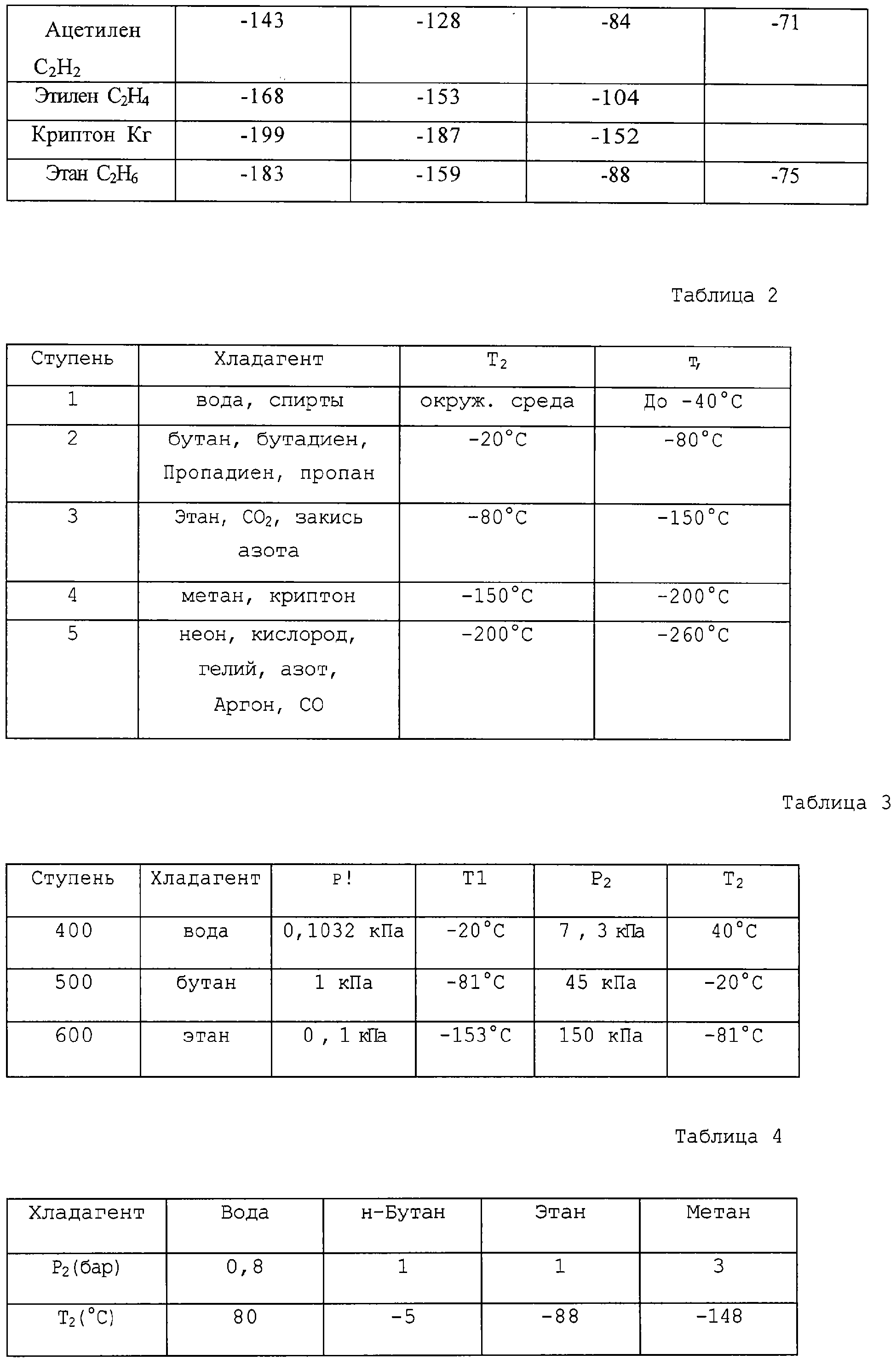
14. Способ по одному из пп.1, 2, 6-8, отличающийся тем, что на первом цикле (100, 400) хладагент выбирают из группы, состоящей из воды, спиртов и их смесей.14. The method according to one of claims 1, 2, 6-8, characterized in that in the first cycle (100, 400) the refrigerant is selected from the group consisting of water, alcohols and mixtures thereof. 15. Способ по п.14, отличающийся тем, что на втором цикле (200, 500) хладагент выбирают из группы, состоящей из бутана, бутадиена, пропадиена, пропана и их смесей.15. The method according to 14, characterized in that in the second cycle (200, 500) the refrigerant is selected from the group consisting of butane, butadiene, propadiene, propane and mixtures thereof. 16. Способ по п.15, отличающийся тем, что он включает в себя третий цикл (300, 600) с хладагентом, выбранным из группы, состоящей из этана, диоксида углерода, закиси азота и их смесей.16. The method according to p. 15, characterized in that it includes a third cycle (300, 600) with a refrigerant selected from the group consisting of ethane, carbon dioxide, nitrous oxide and mixtures thereof. 17. Способ по п.16, отличающийся тем, что он включает в себя четвертый цикл с хладагентом, выбранным из группы, состоящей из метана, криптона и их смесей.17. The method according to clause 16, characterized in that it includes a fourth cycle with a refrigerant selected from the group consisting of methane, krypton and mixtures thereof. 18. Способ по п.17, отличающийся тем, что он включает в себя пятый цикл с хладагентом, выбранным из группы, состоящей из неона, кислорода, гелия, азота, аргона, монооксида углерода и их смесей.18. The method according to 17, characterized in that it includes a fifth cycle with a refrigerant selected from the group consisting of neon, oxygen, helium, nitrogen, argon, carbon monoxide and mixtures thereof. 19. Способ по одному из пп.1, 2, 6-8, отличающийся тем, что по меньшей мере на одном из указанных циклов указанный хладагент имеет скрытую теплоту испарения более 300 кДж/кг, предпочтительно большую или равную примерно 450 кДж/кг.19. The method according to one of claims 1, 2, 6-8, characterized in that at least one of said cycles said refrigerant has a latent heat of vaporization of more than 300 kJ / kg, preferably greater than or equal to about 450 kJ / kg. 20. Способ по одному из пп.1, 2, 6-8, отличающийся тем, что по меньшей мере на одном из указанных циклов температура испарения (T1) в испарителе является максимальной в тройной точке указанного хладагента.20. The method according to one of claims 1, 2, 6-8, characterized in that at least one of these cycles, the evaporation temperature (T 1 ) in the evaporator is maximum at the triple point of the specified refrigerant. 21. Способ по одному из пп.1, 2, 6-8, отличающийся тем, что указанный продукт (Р) первоначально находится в паровой фазе, причем указанный продукт охлаждают до сжижения.21. The method according to one of claims 1, 2, 6-8, characterized in that said product (P) is initially in the vapor phase, said product being cooled to liquefaction. 22. Способ по п.21, отличающийся тем, что указанный продукт (Р) является газом, используемым в качестве топлива, или полимеризуемым сырьем.22. The method according to item 21, wherein the specified product (P) is a gas used as fuel or polymerized raw material. 23. Способ по одному из пп.1, 2, 6-8, отличающийся тем, что указанный продукт (Р) является газом для использования его в качестве сырья, который охлаждают или сжижают при температурах от -80 до -220°С.23. The method according to one of claims 1, 2, 6-8, characterized in that said product (P) is gas for use as a raw material, which is cooled or liquefied at temperatures from -80 to -220 ° C. 24. Устройство для осуществления способа по одному из пп.1-23, включающее в себя N упорядоченных ступеней охлаждения (100, 200, 300, 400, 500, 600) под воздушном вакуумом, причем N является целым числом, превышающим 1, причем каждая ступень содержит:24. A device for implementing the method according to one of claims 1 to 23, including N ordered cooling steps (100, 200, 300, 400, 500, 600) under air vacuum, wherein N is an integer greater than 1, each stage contains: конденсатор (101, 201, 301, 401, 501, 601), содержащий хладагент в жидкой фазе,a condenser (101, 201, 301, 401, 501, 601) containing refrigerant in the liquid phase, испаритель (103, 203, 303, 403, 503, 603), соединенный с указанным конденсатором линией (104, 204, 304, 404, 504, 604),an evaporator (103, 203, 303, 403, 503, 603) connected to the indicated condenser by a line (104, 204, 304, 404, 504, 604), по меньшей мере одну камеру адсорбции/десорбции (120, 220, 320, 421-423, 521-523, 621-623), содержащую цеолитный адсорбент (2) и соединенную с указанным испарителем посредством верхнего клапана (130, 230, 330),at least one adsorption / desorption chamber (120, 220, 320, 421-423, 521-523, 621-623) containing a zeolite adsorbent (2) and connected to the indicated evaporator via an upper valve (130, 230, 330), линию (160, 260, 360, 460, 560, 660), оборудованную нижним клапаном (150, 250, 350), для возврата указанного хладагента из указанной камеры адсорбции/десорбции на указанный конденсатор,a line (160, 260, 360, 460, 560, 660) equipped with a bottom valve (150, 250, 350) for returning said refrigerant from said adsorption / desorption chamber to said condenser, средство нагрева (140, 240, 243, 340) в указанной или в каждой камере адсорбции/десорбции, выполненное с возможностью нагрева цеолитного адсорбента до температуры регенерации,heating means (140, 240, 243, 340) in said or in each adsorption / desorption chamber configured to heat the zeolite adsorbent to a regeneration temperature, причем указанное устройство включает в себя N-1 теплообменников (280, 380), установленных с возможностью обеспечения теплообмена между хладагентом в испарителе (103, 203, 403, 503) одной ступени и хладагентом в конденсаторе (201, 301, 501, 601) следующей по порядку циклов ступени для охлаждения этого последнего и конечный теплообменник (80, 701) установленный с возможностью обеспечения теплообмена между охлаждаемым продуктом (Р) и хладагентом по меньшей мере в испарителе (303, 603).moreover, this device includes N-1 heat exchangers (280, 380) installed with the possibility of providing heat exchange between the refrigerant in the evaporator (103, 203, 403, 503) of one stage and the refrigerant in the condenser (201, 301, 501, 601) of the following in order of stage cycles for cooling the latter, and the final heat exchanger (80, 701) is installed with the possibility of providing heat exchange between the cooled product (P) and the refrigerant in at least the evaporator (303, 603). 25. Устройство по п.24, отличающееся тем, что оно включает в себя теплообменник (126), установленный с возможностью обеспечения теплообмена между хладагентом в конденсаторе (101) первой ступени и окружающей жидкой или газообразной средой при температуре окружающей среды.25. The device according to p. 24, characterized in that it includes a heat exchanger (126) installed with the possibility of providing heat exchange between the refrigerant in the condenser (101) of the first stage and the surrounding liquid or gaseous medium at ambient temperature. 26. Устройство по п.24 или 25, отличающееся тем, что оно содержит используемый для нагрева по меньшей мере одной из камер адсорбции/десорбции (521-523, 621-623) и регенерации цеолитного адсорбента (2) теплообменник (540, 640), установленный с возможностью обеспечения теплообмена между цеолитным адсорбентом (2) и атмосферным воздухом.26. The device according to paragraph 24 or 25, characterized in that it contains used for heating at least one of the adsorption / desorption chambers (521-523, 621-623) and regeneration of the zeolite adsorbent (2) heat exchanger (540, 640) installed with the possibility of providing heat exchange between the zeolite adsorbent (2) and atmospheric air. 27. Устройство по п.24 или 25, отличающееся тем, что оно включает в себя, по меньшей мере на одной из указанных ступеней, устройство (435, 535, 635) фрагментации струи, установленное с возможностью распыления хладагента в жидкой фазе при его введении в испаритель(403, 503, 603).27. The device according to paragraph 24 or 25, characterized in that it includes, at least at one of these stages, a device (435, 535, 635) for fragmentation of the jet, installed with the possibility of atomization of the refrigerant in the liquid phase when it is introduced to the evaporator (403, 503, 603). 28. Устройство по п.24 или 25, отличающееся тем, что по меньшей мере на одной из указанных ступеней между указанной камерой или между каждой камерой адсорбции/десорбции (220, 320) и указанным конденсатором (201, 301) установлена камера охлаждения (216, 316) хладагента, которая находится в тепловом контакте с источником тепла, находящегося при температуре окружающей среды.28. The device according to paragraph 24 or 25, characterized in that at least at one of the indicated steps between the specified chamber or between each adsorption / desorption chamber (220, 320) and said condenser (201, 301), a cooling chamber (216) is installed , 316) a refrigerant that is in thermal contact with a heat source at ambient temperature. 29. Устройство по п.24 или 25, отличающееся тем, что оно в качестве средства нагрева указанных камер адсорбции/десорбции включает в себя по меньшей мере один теплообменник (290), предпочтительно по меньшей мере N-1 теплообменников, выполненных с возможностью обеспечения теплообмена между указанным цеолитным адсорбентом (2) в ходе адсорбции в камере или в одной из камер адсорбции/десорбции (121) одной ступени и цеолитным адсорбентом (2) в ходе регенерации в указанной камере или в одной из указанных камер адсорбции/десорбции (223) следующей ступени.29. The device according to paragraph 24 or 25, characterized in that it as a means of heating said adsorption / desorption chambers includes at least one heat exchanger (290), preferably at least N-1 heat exchangers configured to provide heat exchange between the indicated zeolite adsorbent (2) during adsorption in the chamber or in one of the adsorption / desorption chambers (121) of one step and the zeolite adsorbent (2) during the regeneration in the specified chamber or in one of the indicated adsorption / desorption chambers (223) of the following steps. 30. Устройство по п.24 или 25, отличающееся тем, что оно в качестве средства охлаждения указанных камер адсорбции/десорбции включает в себя по меньшей мере N-1 теплообменников (280, 380), установленных с возможностью обеспечения теплообмена между хладагентом в испарителе (103, 203) одной ступени и указанным цеолитным адсорбентом (2) в указанной камере или в каждой камере адсорбции/десорбции (221, 222, 223, 320) следующей ступени.30. The device according to paragraph 24 or 25, characterized in that it as a means of cooling said adsorption / desorption chambers includes at least N-1 heat exchangers (280, 380) installed with the possibility of providing heat exchange between the refrigerant in the evaporator ( 103, 203) of one step and said zeolite adsorbent (2) in said chamber or in each adsorption / desorption chamber (221, 222, 223, 320) of the next step. 31. Устройство по п.24 или 25, отличающееся тем, что каждая ступень содержит по меньшей мере две камеры адсорбции/десорбции (121, 122, 123), каждая из которых соединена с испарителем (103) через соответствующий верхний клапан (131, 132, 133) и с конденсатором (101) через один из соответствующих нижних клапанов (151, 152, 153).31. The device according to paragraph 24 or 25, characterized in that each stage contains at least two adsorption / desorption chambers (121, 122, 123), each of which is connected to the evaporator (103) through the corresponding upper valve (131, 132 , 133) and with a condenser (101) through one of the corresponding lower valves (151, 152, 153). 32. Устройство по п.31, отличающееся тем, что оно включает в себя средство управления клапанами (105), запрограммированное на открывание и закрывание указанных верхних и нижних клапанов согласно циклу скрытого времени, на котором в каждой камере (121, 122, 123) последовательно осуществляют этап адсорбции, на котором верхний клапан (131) открыт, а нижний клапан (151) закрыт, этап регенерации или десорбции, на котором нижний клапан (153) открыт, а верхний клапан (133) закрыт, и этап охлаждения после регенерации, на котором нижний клапан (152) и верхний клапан (132) закрыты.32. The device according to p. 31, characterized in that it includes a valve control (105), programmed to open and close the specified upper and lower valves according to a latent time cycle, in which in each chamber (121, 122, 123) sequentially carry out the adsorption step, in which the upper valve (131) is open and the lower valve (151) is closed, the regeneration or desorption step, in which the lower valve (153) is open and the upper valve (133) is closed, and the cooling step after regeneration, on which the lower valve (152) and the upper valve (132) are closed digging. 33. Устройство по п.24 или 25, отличающееся тем, что оно соединено с камерой (1), содержащей указанный охлаждаемый продукт Р, причем змеевик (26) конечного теплообменника подвешен внутри указанной камеры для обмена теплом между хладагентом в испарителе (303) последней ступени и продуктом (Р) в жидкой или паровой фазе, содержащимся в указанной камере.33. The device according to paragraph 24 or 25, characterized in that it is connected to the chamber (1) containing the specified cooled product P, and the coil (26) of the final heat exchanger is suspended inside the specified chamber for exchanging heat between the refrigerant in the evaporator (303) of the latter stage and product (P) in the liquid or vapor phase contained in the specified chamber. 34. Судно для перевозки метана, включающее в себя устройство по п.33 в качестве холодильной установки повторного сжижения, в котором камера (1) предназначена для хранения охлаждаемого продукта Р.34. A methane transport vessel including a device according to claim 33 as a re-liquefaction refrigeration unit, in which a chamber (1) is designed to store a refrigerated product R. 35. Завод по сжижению газа, включающий устройство по п.33, в котором камера (1) предназначена для хранения охлаждаемого продукта Р.35. A gas liquefaction plant, comprising a device according to claim 33, wherein the chamber (1) is designed to store a refrigerated product R.
RU2005141485/06A 2003-06-06 2004-06-04 Method and device for product cooling, particularly for gas liquefaction RU2313740C2 (en)

Applications Claiming Priority (2)

Application Number Priority Date Filing Date Title
FR0306839A FR2855869B1 (en) 2003-06-06 2003-06-06 METHOD FOR COOLING A PRODUCT, IN PARTICULAR FOR THE LIQUEFACTION OF A GAS, AND DEVICE FOR IMPLEMENTING IT
FR03/06839 2003-06-06

Publications (2)

Publication Number Publication Date
RU2005141485A RU2005141485A (en) 2006-08-27
RU2313740C2 true RU2313740C2 (en) 2007-12-27

Family

ID=33443188

Family Applications (1)

Application Number Title Priority Date Filing Date
RU2005141485/06A RU2313740C2 (en) 2003-06-06 2004-06-04 Method and device for product cooling, particularly for gas liquefaction

Country Status (13)

Country Link
US (1) US7293421B2 (en)
EP (1) EP1631774B1 (en)
JP (1) JP4102845B2 (en)
KR (1) KR100763072B1 (en)
CN (1) CN100436965C (en)
DE (1) DE602004008461T2 (en)
EG (1) EG23850A (en)
ES (1) ES2289552T3 (en)
FR (1) FR2855869B1 (en)
NO (1) NO335703B1 (en)
OA (1) OA13211A (en)
RU (1) RU2313740C2 (en)
WO (1) WO2004111556A1 (en)

Cited By (1)

* Cited by examiner, † Cited by third party
Publication number Priority date Publication date Assignee Title
RU2601670C1 (en) * 2015-07-22 2016-11-10 Федеральное Государственное Автономное Образовательное Учреждение Высшего Профессионального Образования "Дальневосточный Федеральный Университет" (Двфу) Cooling machine

Families Citing this family (26)

* Cited by examiner, † Cited by third party
Publication number Priority date Publication date Assignee Title
US20090266101A1 (en) * 2006-08-04 2009-10-29 Koninklijke Philips Electronics N.V. Domestic beverage dispensing apparatus comprising an adsorbent cooling device
FR2909078B1 (en) * 2006-11-24 2009-01-09 Inst Francais Du Petrole FUEL STORAGE FACILITY AND METHOD OF FILLING AND / OR EMPTYING THE TANKS OF THIS FACILITY
TW200837967A (en) * 2007-03-15 2008-09-16 Motech Ind Inc Method for bow reduction of composite sheet
US8739566B2 (en) 2007-04-30 2014-06-03 Oxicool, Inc. Motor cycle air conditioning system
US20100043462A1 (en) * 2008-06-10 2010-02-25 Oxicool, Inc. Air Conditioning System
US8425674B2 (en) * 2008-10-24 2013-04-23 Exxonmobil Research And Engineering Company System using unutilized heat for cooling and/or power generation
FR2938003A1 (en) * 2008-11-05 2010-05-07 Claude Antoine Blaizat Electricity producing method, involves maintaining hot and cold sources at specific temperature, preheating power gas, and selecting hot and cold sources based on available thermal power and requested electric output
WO2011016809A1 (en) * 2009-08-06 2011-02-10 Oxicool, Inc. Air conditioning system
KR100949946B1 (en) * 2009-08-24 2010-03-30 주식회사 코스모센추리 Thermoelectric element power generating apparatus using sunlight
US8707730B2 (en) * 2009-12-07 2014-04-29 Alkane, Llc Conditioning an ethane-rich stream for storage and transportation
US20110219802A1 (en) * 2010-03-09 2011-09-15 Exxonmobil Research And Engineering Company Sorption systems having improved cycle times
FR2965335A1 (en) 2010-09-27 2012-03-30 Gaztransp Et Technigaz ADSORPTION REFRIGERATION SYSTEM
CN102466380A (en) * 2010-11-15 2012-05-23 中兴电工机械股份有限公司 Method for controlling absorption air-conditioning equipment
DE102010062869A1 (en) * 2010-12-10 2012-06-14 Robert Bosch Gmbh An air conditioning apparatus, an air conditioning unit, a method of air conditioning an interior, and a method of operating an air conditioning unit
KR101287975B1 (en) 2010-12-21 2013-07-22 한국과학기술원 Cascaded cryogenic sorption liquefaction cycle for LNG-FPSO
US9239174B2 (en) * 2011-02-17 2016-01-19 Rocky Research Cascade floating intermediate temperature heat pump system
US11885561B2 (en) * 2012-12-04 2024-01-30 Conocophillips Company Low global-warming refrigerants in LNG processing
DE102013114159A1 (en) 2013-04-12 2014-10-16 Arvid Rauchschwalbe Methods and apparatus for using thermal energy and for generating temperature level differences
KR102140629B1 (en) 2015-11-09 2020-08-03 벡텔 하이드로카본 테크놀로지 솔루션즈, 인코포레이티드 Systems and methods for multistage cooling
US20170217592A1 (en) * 2016-02-01 2017-08-03 General Electric Company Aircraft Thermal Management System
AT518923A1 (en) * 2016-08-09 2018-02-15 Rep Ip Ag transport container
FR3059000B1 (en) * 2016-11-24 2020-01-24 Centre National De La Recherche Scientifique SYSTEM AND METHOD FOR PURIFYING LIQUID BY REVERSE OSMOSIS.
JP2018194194A (en) * 2017-05-12 2018-12-06 カルソニックカンセイ株式会社 Adsorption type refrigeration system, and air conditioning device for vehicle including adsorption type refrigeration system
WO2020242401A1 (en) * 2019-05-30 2020-12-03 Maxeff Teknoloji̇ Anoni̇m Şi̇rketi̇ Absorption heating and cooling system with increased energy efficiency
CN113339905B (en) * 2021-05-27 2022-09-27 五邑大学 Air conditioner based on molecular sieve
WO2023172251A1 (en) 2022-03-08 2023-09-14 Bechtel Energy Technologies & Solutions, Inc. Systems and methods for regenerative ejector-based cooling cycles

Family Cites Families (8)

* Cited by examiner, † Cited by third party
Publication number Priority date Publication date Assignee Title
US5729988A (en) * 1974-11-04 1998-03-24 Tchernev; Dimiter I. Heat pump energized by low-grade heat source
US4827728A (en) * 1986-11-24 1989-05-09 Martin Marietta Energy Systems, Inc. Seven-effect absorption refrigeration
US5598721A (en) * 1989-03-08 1997-02-04 Rocky Research Heating and air conditioning systems incorporating solid-vapor sorption reactors capable of high reaction rates
US5339649A (en) * 1991-12-09 1994-08-23 Kabushikikaisha Equos Research Cryogenic refrigerator
KR19990067267A (en) * 1995-11-01 1999-08-16 존 제이. 주니어 바우어 Even adsorption chiller
US5761925A (en) * 1995-12-21 1998-06-09 Ebara Corporation Absorption heat pump and desiccant assisted air conditioner
TW421704B (en) * 1998-11-18 2001-02-11 Shell Internattonale Res Mij B Plant for liquefying natural gas
AT408916B (en) * 1999-12-13 2002-04-25 Vaillant Gmbh ADSORPTION HEAT PUMP WITH SEVERAL MODULES

Non-Patent Citations (1)

* Cited by examiner, † Cited by third party
Title
СОРОКИН А.И. и др., Сжиженный метан за рубежом, - Москва, «Недра» 1965, стр.50-52. *

Cited By (1)

* Cited by examiner, † Cited by third party
Publication number Priority date Publication date Assignee Title
RU2601670C1 (en) * 2015-07-22 2016-11-10 Федеральное Государственное Автономное Образовательное Учреждение Высшего Профессионального Образования "Дальневосточный Федеральный Университет" (Двфу) Cooling machine

Also Published As

Publication number Publication date
EG23850A (en) 2007-10-29
DE602004008461T2 (en) 2008-05-15
OA13211A (en) 2006-12-13
AU2004247914A1 (en) 2004-12-23
KR100763072B1 (en) 2007-10-04
DE602004008461D1 (en) 2007-10-04
FR2855869A1 (en) 2004-12-10
EP1631774B1 (en) 2007-08-22
NO20060017L (en) 2006-03-06
NO335703B1 (en) 2015-01-26
KR20060038942A (en) 2006-05-04
EP1631774A1 (en) 2006-03-08
ES2289552T3 (en) 2008-02-01
JP2006527348A (en) 2006-11-30
US20060254290A1 (en) 2006-11-16
FR2855869B1 (en) 2008-01-04
US7293421B2 (en) 2007-11-13
CN100436965C (en) 2008-11-26
CN1813161A (en) 2006-08-02
JP4102845B2 (en) 2008-06-18
WO2004111556A1 (en) 2004-12-23
RU2005141485A (en) 2006-08-27

Similar Documents

Publication Publication Date Title
RU2313740C2 (en) Method and device for product cooling, particularly for gas liquefaction
US7121116B2 (en) Method and device for producing oxygen
JP5410443B2 (en) Method and system for adjusting the cooling capacity of a cooling system based on a gas expansion process
ES2237717T3 (en) HYBRID CYCLE FOR LIQUID NATURAL GAS PRODUCTION.
ES2234497T3 (en) GAS LICUATION PROCEDURE USED BY A SINGLE MIXED COOLING CIRCUIT.
JP2690464B2 (en) Method for recovering volatile organic compounds from gas streams
CA2893197C (en) Argon production method and apparatus
US20110259044A1 (en) Method and apparatus for producing liquefied natural gas
JPH07507864A (en) Method and apparatus for cooling fluids, especially for liquefying natural gas
KR860001329A (en) High Purity Nitrogen Gas Production Equipment
US20120000242A1 (en) Method and apparatus for storing liquefied natural gas
KR100902911B1 (en) Apparatus for Enriching and Purifying Waste Helium Gases
JP4210568B2 (en) Refrigeration method and system
KR100618735B1 (en) Air separator and operation method thereof
JP2004163089A5 (en)
CA2567586A1 (en) Method of re-gasification of liquid natural gas to generate liquid air
KR20220157389A (en) Facility and method for hydrogen refrigeration
KR100869518B1 (en) Method and apparatus for Cryogenic Helium Purification
WO2022087491A1 (en) Heating and refrigeration system
JPS59164874A (en) Device for manufacturing nitrogen gas
JPS6353470B2 (en)
JPS646121B2 (en)
WO1999022187A1 (en) Phase-changeable and non-heat refrigeration process and apparatus thereof
JPH04161770A (en) Liquefaction machine
JPH028234B2 (en)

Legal Events

Date Code Title Description
MM4A The patent is invalid due to non-payment of fees

Effective date: 20170605