RU2301835C2 - Method and device for continuous production of steel with the use of starting metal material - Google Patents
Method and device for continuous production of steel with the use of starting metal material Download PDFInfo
- Publication number
- RU2301835C2 RU2301835C2 RU2004127233/02A RU2004127233A RU2301835C2 RU 2301835 C2 RU2301835 C2 RU 2301835C2 RU 2004127233/02 A RU2004127233/02 A RU 2004127233/02A RU 2004127233 A RU2004127233 A RU 2004127233A RU 2301835 C2 RU2301835 C2 RU 2301835C2
- Authority
- RU
- Russia
- Prior art keywords
- afterburning
- gases
- melting unit
- inner chamber
- melting
- Prior art date
Links
Images


Classifications
-
- C—CHEMISTRY; METALLURGY
- C21—METALLURGY OF IRON
- C21C—PROCESSING OF PIG-IRON, e.g. REFINING, MANUFACTURE OF WROUGHT-IRON OR STEEL; TREATMENT IN MOLTEN STATE OF FERROUS ALLOYS
- C21C5/00—Manufacture of carbon-steel, e.g. plain mild steel, medium carbon steel or cast steel or stainless steel
- C21C5/56—Manufacture of steel by other methods
-
- C—CHEMISTRY; METALLURGY
- C21—METALLURGY OF IRON
- C21B—MANUFACTURE OF IRON OR STEEL
- C21B13/00—Making spongy iron or liquid steel, by direct processes
- C21B13/02—Making spongy iron or liquid steel, by direct processes in shaft furnaces
- C21B13/023—Making spongy iron or liquid steel, by direct processes in shaft furnaces wherein iron or steel is obtained in a molten state
-
- C—CHEMISTRY; METALLURGY
- C21—METALLURGY OF IRON
- C21B—MANUFACTURE OF IRON OR STEEL
- C21B13/00—Making spongy iron or liquid steel, by direct processes
- C21B13/14—Multi-stage processes processes carried out in different vessels or furnaces
-
- C—CHEMISTRY; METALLURGY
- C21—METALLURGY OF IRON
- C21C—PROCESSING OF PIG-IRON, e.g. REFINING, MANUFACTURE OF WROUGHT-IRON OR STEEL; TREATMENT IN MOLTEN STATE OF FERROUS ALLOYS
- C21C5/00—Manufacture of carbon-steel, e.g. plain mild steel, medium carbon steel or cast steel or stainless steel
- C21C5/56—Manufacture of steel by other methods
- C21C5/562—Manufacture of steel by other methods starting from scrap
- C21C5/565—Preheating of scrap
-
- C—CHEMISTRY; METALLURGY
- C21—METALLURGY OF IRON
- C21C—PROCESSING OF PIG-IRON, e.g. REFINING, MANUFACTURE OF WROUGHT-IRON OR STEEL; TREATMENT IN MOLTEN STATE OF FERROUS ALLOYS
- C21C5/00—Manufacture of carbon-steel, e.g. plain mild steel, medium carbon steel or cast steel or stainless steel
- C21C5/56—Manufacture of steel by other methods
- C21C5/567—Manufacture of steel by other methods operating in a continuous way
-
- F—MECHANICAL ENGINEERING; LIGHTING; HEATING; WEAPONS; BLASTING
- F27—FURNACES; KILNS; OVENS; RETORTS
- F27B—FURNACES, KILNS, OVENS, OR RETORTS IN GENERAL; OPEN SINTERING OR LIKE APPARATUS
- F27B1/00—Shaft or like vertical or substantially vertical furnaces
- F27B1/02—Shaft or like vertical or substantially vertical furnaces with two or more shafts or chambers, e.g. multi-storey
- F27B1/025—Shaft or like vertical or substantially vertical furnaces with two or more shafts or chambers, e.g. multi-storey with fore-hearth
-
- F—MECHANICAL ENGINEERING; LIGHTING; HEATING; WEAPONS; BLASTING
- F27—FURNACES; KILNS; OVENS; RETORTS
- F27B—FURNACES, KILNS, OVENS, OR RETORTS IN GENERAL; OPEN SINTERING OR LIKE APPARATUS
- F27B3/00—Hearth-type furnaces, e.g. of reverberatory type; Tank furnaces
- F27B3/06—Hearth-type furnaces, e.g. of reverberatory type; Tank furnaces with movable working chambers or hearths, e.g. tiltable, oscillating or describing a composed movement
-
- F—MECHANICAL ENGINEERING; LIGHTING; HEATING; WEAPONS; BLASTING
- F27—FURNACES; KILNS; OVENS; RETORTS
- F27B—FURNACES, KILNS, OVENS, OR RETORTS IN GENERAL; OPEN SINTERING OR LIKE APPARATUS
- F27B3/00—Hearth-type furnaces, e.g. of reverberatory type; Tank furnaces
- F27B3/08—Hearth-type furnaces, e.g. of reverberatory type; Tank furnaces heated electrically, with or without any other source of heat
- F27B3/085—Arc furnaces
-
- F—MECHANICAL ENGINEERING; LIGHTING; HEATING; WEAPONS; BLASTING
- F27—FURNACES; KILNS; OVENS; RETORTS
- F27D—DETAILS OR ACCESSORIES OF FURNACES, KILNS, OVENS, OR RETORTS, IN SO FAR AS THEY ARE OF KINDS OCCURRING IN MORE THAN ONE KIND OF FURNACE
- F27D3/00—Charging; Discharging; Manipulation of charge
- F27D3/16—Introducing a fluid jet or current into the charge
-
- C—CHEMISTRY; METALLURGY
- C21—METALLURGY OF IRON
- C21C—PROCESSING OF PIG-IRON, e.g. REFINING, MANUFACTURE OF WROUGHT-IRON OR STEEL; TREATMENT IN MOLTEN STATE OF FERROUS ALLOYS
- C21C5/00—Manufacture of carbon-steel, e.g. plain mild steel, medium carbon steel or cast steel or stainless steel
- C21C5/28—Manufacture of steel in the converter
- C21C5/30—Regulating or controlling the blowing
- C21C5/305—Afterburning
-
- F—MECHANICAL ENGINEERING; LIGHTING; HEATING; WEAPONS; BLASTING
- F27—FURNACES; KILNS; OVENS; RETORTS
- F27B—FURNACES, KILNS, OVENS, OR RETORTS IN GENERAL; OPEN SINTERING OR LIKE APPARATUS
- F27B1/00—Shaft or like vertical or substantially vertical furnaces
- F27B1/10—Details, accessories, or equipment peculiar to furnaces of these types
- F27B1/16—Arrangements of tuyeres
-
- F—MECHANICAL ENGINEERING; LIGHTING; HEATING; WEAPONS; BLASTING
- F27—FURNACES; KILNS; OVENS; RETORTS
- F27B—FURNACES, KILNS, OVENS, OR RETORTS IN GENERAL; OPEN SINTERING OR LIKE APPARATUS
- F27B3/00—Hearth-type furnaces, e.g. of reverberatory type; Tank furnaces
- F27B3/10—Details, accessories, or equipment peculiar to hearth-type furnaces
- F27B3/19—Arrangements of devices for discharging
-
- F—MECHANICAL ENGINEERING; LIGHTING; HEATING; WEAPONS; BLASTING
- F27—FURNACES; KILNS; OVENS; RETORTS
- F27D—DETAILS OR ACCESSORIES OF FURNACES, KILNS, OVENS, OR RETORTS, IN SO FAR AS THEY ARE OF KINDS OCCURRING IN MORE THAN ONE KIND OF FURNACE
- F27D3/00—Charging; Discharging; Manipulation of charge
- F27D3/16—Introducing a fluid jet or current into the charge
- F27D2003/162—Introducing a fluid jet or current into the charge the fluid being an oxidant or a fuel
- F27D2003/163—Introducing a fluid jet or current into the charge the fluid being an oxidant or a fuel the fluid being an oxidant
- F27D2003/164—Oxygen
-
- F—MECHANICAL ENGINEERING; LIGHTING; HEATING; WEAPONS; BLASTING
- F27—FURNACES; KILNS; OVENS; RETORTS
- F27D—DETAILS OR ACCESSORIES OF FURNACES, KILNS, OVENS, OR RETORTS, IN SO FAR AS THEY ARE OF KINDS OCCURRING IN MORE THAN ONE KIND OF FURNACE
- F27D3/00—Charging; Discharging; Manipulation of charge
- F27D3/16—Introducing a fluid jet or current into the charge
- F27D2003/162—Introducing a fluid jet or current into the charge the fluid being an oxidant or a fuel
- F27D2003/165—Introducing a fluid jet or current into the charge the fluid being an oxidant or a fuel the fluid being a fuel
-
- F—MECHANICAL ENGINEERING; LIGHTING; HEATING; WEAPONS; BLASTING
- F27—FURNACES; KILNS; OVENS; RETORTS
- F27D—DETAILS OR ACCESSORIES OF FURNACES, KILNS, OVENS, OR RETORTS, IN SO FAR AS THEY ARE OF KINDS OCCURRING IN MORE THAN ONE KIND OF FURNACE
- F27D3/00—Charging; Discharging; Manipulation of charge
- F27D3/16—Introducing a fluid jet or current into the charge
- F27D2003/167—Introducing a fluid jet or current into the charge the fluid being a neutral gas
-
- F—MECHANICAL ENGINEERING; LIGHTING; HEATING; WEAPONS; BLASTING
- F27—FURNACES; KILNS; OVENS; RETORTS
- F27D—DETAILS OR ACCESSORIES OF FURNACES, KILNS, OVENS, OR RETORTS, IN SO FAR AS THEY ARE OF KINDS OCCURRING IN MORE THAN ONE KIND OF FURNACE
- F27D3/00—Charging; Discharging; Manipulation of charge
- F27D3/16—Introducing a fluid jet or current into the charge
- F27D2003/168—Introducing a fluid jet or current into the charge through a lance
- F27D2003/169—Construction of the lance, e.g. lances for injecting particles
-
- F—MECHANICAL ENGINEERING; LIGHTING; HEATING; WEAPONS; BLASTING
- F27—FURNACES; KILNS; OVENS; RETORTS
- F27D—DETAILS OR ACCESSORIES OF FURNACES, KILNS, OVENS, OR RETORTS, IN SO FAR AS THEY ARE OF KINDS OCCURRING IN MORE THAN ONE KIND OF FURNACE
- F27D17/00—Arrangements for using waste heat; Arrangements for using, or disposing of, waste gases
- F27D17/004—Systems for reclaiming waste heat
- F27D2017/005—Systems for reclaiming waste heat including pyrolising the waste gases
-
- F—MECHANICAL ENGINEERING; LIGHTING; HEATING; WEAPONS; BLASTING
- F27—FURNACES; KILNS; OVENS; RETORTS
- F27D—DETAILS OR ACCESSORIES OF FURNACES, KILNS, OVENS, OR RETORTS, IN SO FAR AS THEY ARE OF KINDS OCCURRING IN MORE THAN ONE KIND OF FURNACE
- F27D19/00—Arrangements of controlling devices
- F27D2019/0006—Monitoring the characteristics (composition, quantities, temperature, pressure) of at least one of the gases of the kiln atmosphere and using it as a controlling value
- F27D2019/0012—Monitoring the composition of the atmosphere or of one of their components
-
- F—MECHANICAL ENGINEERING; LIGHTING; HEATING; WEAPONS; BLASTING
- F27—FURNACES; KILNS; OVENS; RETORTS
- F27D—DETAILS OR ACCESSORIES OF FURNACES, KILNS, OVENS, OR RETORTS, IN SO FAR AS THEY ARE OF KINDS OCCURRING IN MORE THAN ONE KIND OF FURNACE
- F27D99/00—Subject matter not provided for in other groups of this subclass
- F27D99/0001—Heating elements or systems
- F27D99/0006—Electric heating elements or system
- F27D2099/0021—Arc heating
- F27D2099/0023—DC arc heating
-
- F—MECHANICAL ENGINEERING; LIGHTING; HEATING; WEAPONS; BLASTING
- F27—FURNACES; KILNS; OVENS; RETORTS
- F27D—DETAILS OR ACCESSORIES OF FURNACES, KILNS, OVENS, OR RETORTS, IN SO FAR AS THEY ARE OF KINDS OCCURRING IN MORE THAN ONE KIND OF FURNACE
- F27D3/00—Charging; Discharging; Manipulation of charge
- F27D3/12—Travelling or movable supports or containers for the charge
- F27D3/123—Furnace cars
-
- F—MECHANICAL ENGINEERING; LIGHTING; HEATING; WEAPONS; BLASTING
- F27—FURNACES; KILNS; OVENS; RETORTS
- F27M—INDEXING SCHEME RELATING TO ASPECTS OF THE CHARGES OR FURNACES, KILNS, OVENS OR RETORTS
- F27M2001/00—Composition, conformation or state of the charge
- F27M2001/10—Scrap material used as charge
-
- Y—GENERAL TAGGING OF NEW TECHNOLOGICAL DEVELOPMENTS; GENERAL TAGGING OF CROSS-SECTIONAL TECHNOLOGIES SPANNING OVER SEVERAL SECTIONS OF THE IPC; TECHNICAL SUBJECTS COVERED BY FORMER USPC CROSS-REFERENCE ART COLLECTIONS [XRACs] AND DIGESTS
- Y02—TECHNOLOGIES OR APPLICATIONS FOR MITIGATION OR ADAPTATION AGAINST CLIMATE CHANGE
- Y02P—CLIMATE CHANGE MITIGATION TECHNOLOGIES IN THE PRODUCTION OR PROCESSING OF GOODS
- Y02P10/00—Technologies related to metal processing
- Y02P10/20—Recycling
Landscapes
- Engineering & Computer Science (AREA)
- Chemical & Material Sciences (AREA)
- Manufacturing & Machinery (AREA)
- Materials Engineering (AREA)
- Metallurgy (AREA)
- Organic Chemistry (AREA)
- Mechanical Engineering (AREA)
- General Engineering & Computer Science (AREA)
- Vertical, Hearth, Or Arc Furnaces (AREA)
- Furnace Details (AREA)
- Waste-Gas Treatment And Other Accessory Devices For Furnaces (AREA)
- Treatment Of Steel In Its Molten State (AREA)
- Refinement Of Pig-Iron, Manufacture Of Cast Iron, And Steel Manufacture Other Than In Revolving Furnaces (AREA)
- Carbon Steel Or Casting Steel Manufacturing (AREA)
Abstract
Description
Изобретение касается способа непрерывного производства стали с применением металлических исходных материалов, например лома, губчатого железа или тому подобного, причем исходный материал предварительно нагревается в верхней части плавильного агрегата, затем расплавляется в нижней части плавильного агрегата за счет подвода топлива, причем расплав непрерывно отводится в емкость для обработки, в которой достигается желаемое качество стали, а в плавильный агрегат снаружи подаются газы для дожигания технологических газов.The invention relates to a method for the continuous production of steel using metal starting materials, for example scrap, sponge iron or the like, the starting material being preheated in the upper part of the melting unit, then melted in the lower part of the melting unit by supplying fuel, and the melt is continuously discharged into the tank for processing in which the desired quality of steel is achieved, and gases are supplied to the melting unit from the outside for afterburning of the process gases.
Кроме того, изобретение относится к устройству непрерывного производства стали с применением металлического исходного материала, которое содержит плавильный агрегат с, по меньшей мере, одной горелкой для ископаемого топлива, расположенной в нижней части плавильного агрегата, предназначенной для нагрева металлических исходных материалов, а также соединенную с нижней частью плавильного агрегата посредством выпускного отверстия емкость для обработки, в которую непрерывно подается расплав и в которой достигается желаемое качество стали, причем исходные материалы предварительно нагреваются технологическими газами в верхней части плавильного агрегата, а в плавильный агрегат снаружи подаются газы для дожигания технологических газов. В емкости для обработки расплав, например, нагревается, и осуществляется операция легирования для получения нужного состава стали.In addition, the invention relates to a device for the continuous production of steel using a metal source material, which comprises a melting unit with at least one fossil fuel burner located in the lower part of the melting unit, intended for heating the metal starting materials, and also connected to the lower part of the melting unit by means of an outlet, a processing vessel into which the melt is continuously supplied and in which the desired quality is achieved and, and the source materials are preheated with process gases in the upper part of the melting unit, and gases are supplied to the melting unit from the outside for afterburning of the process gases. In the processing vessel, the melt, for example, is heated, and an alloying operation is performed to obtain the desired steel composition.
Подобные способ и устройство известны из документа DT 2325593, в котором описан способ непрерывного изготовления стали из исходных материалов, например скрапа, губчатого железа или подобного материала, которые непрерывно расплавляются в нижней части шахтной печи, выполняющей функцию плавильного агрегата посредством горелки, а расплав переливается в нагреваемый проточный сосуд, в котором непрерывно осуществляется скачивание шлака, и при этом находящийся в ковше материал нагревается и благодаря введению соответствующих легирующих или раскисляющих добавок устанавливается желаемый химический состав стали. При этом нагрев и восстановление шлаков осуществляются электрически. К тому же, проточный сосуд нагревается индуктивно или посредством электрической дуги. В шахтную печь с помощью направляющей вводится выполненная в виде копья топливокислородная горелка, подвижная внутри плавильного агрегата в вертикальном направлении, причем пламя горелки подводится под исходный материал и непрерывно плавит его снизу. Благодаря кольцевой щели в боковой поверхности шахтной печи может подводиться воздух для дожигания технологических газов, которые служат для предварительного нагрева расплавляемых материалов. Плавильный агрегат внутри сформирован по существу цилиндрическим и может иметь немного увеличивающийся книзу диаметр.A similar method and device is known from DT 2325593, which describes a method for the continuous production of steel from raw materials, for example scrap, sponge iron or similar material, which are continuously melted in the lower part of the shaft furnace, which acts as a melting unit by means of a burner, and the melt is poured into a heated flow vessel in which slag is continuously charged, while the material in the bucket is heated and due to the introduction of appropriate alloying or removing additives, the desired chemical composition of the steel is established. In this case, the heating and recovery of slag is carried out electrically. In addition, the flow vessel is heated inductively or by means of an electric arc. A fuel-oxygen burner made in the form of a spear is introduced into the shaft furnace using a spear, movable vertically inside the melting unit, and the burner flame is fed under the source material and continuously melts it from below. Due to the annular gap in the lateral surface of the shaft furnace, air can be supplied for the afterburning of process gases, which serve to pre-heat the molten materials. The melting unit inside is formed substantially cylindrical and may have a diameter slightly increasing downward.
В журнале "Stahl und Eisen", 92 (1972), №11, стр.501 также описан непрерывный способ плавки лома, в котором осуществляется принцип противотока. При этом способе работы столб лома расплавляется снизу мазут-кислородной горелкой.In the journal "Stahl und Eisen", 92 (1972), No. 11, p. 501, a continuous method of scrap melting is also described, in which the counterflow principle is implemented. With this method of operation, the scrap column is melted from below by a fuel oil-oxygen burner.
Расплавленный металл непрерывно вытекает вместе с образовавшимся железооксидным шлаком из плавильного ковша. Одновременно столб лома пополняется посредством проходящего добавления. При этом проблемой является то, что хотя присутствует заметный нагрев, но часть химически связанного тепла отходящих газов для предварительного нагрева остается не использованной. Кроме того, способ связан с проблемой высокого ошлаковывания железа при использовании ископаемых горючих материалов в комбинации с кислородом.The molten metal flows continuously with the iron oxide slag from the smelter. At the same time, the scrap column is replenished by means of a passing addition. The problem is that although there is noticeable heating, but part of the chemically bound heat of the exhaust gases for preheating remains unused. In addition, the method is associated with the problem of high slagging of iron when using fossil combustible materials in combination with oxygen.
Кроме того, в журнале "Stahl und Eisen", 115 (1995), №5, стр.75 описан другой вариант. При этом лом предварительно нагревается в колонне для предварительного нагрева и расплавляется в реакторе с железным расплавом. Предварительный нагрев может осуществляться в реакторе с железным расплавом непосредственно перед плавлением, или лом предварительно нагревается в расположенном вверху плавильного реактора коробе, а затем свободно падает в реактор. При плавлении в ванну железного расплава совместно вдуваются уголь и кислород, причем отходящие газы могут дожигаться над расплавом в реакторе. Чтобы минимизировать окисление лома при предварительном нагреве, отходящие печные газы дожигаются при нагреве ступенчато.In addition, Stahl und Eisen, 115 (1995), No. 5, p. 75, describes another option. When this scrap is preheated in the column for preheating and melts in a reactor with an iron melt. Preheating can be carried out in a molten iron reactor immediately before melting, or the scrap is preheated in the duct located at the top of the melting reactor, and then freely falls into the reactor. When melting into a bath of iron melt, coal and oxygen are co-blown together, and the exhaust gases can be burned over the melt in the reactor. In order to minimize the oxidation of scrap during preheating, the off-gas from the furnace gases is burned up step by step during heating.
Задачей настоящего изобретения является улучшение показателей работы соответствующего родовому понятию способа или соответственно устройства, в которых используется энергия ископаемого топлива для расплавления, а также химического тепла отходящих газов для предварительного нагрева исходных материалов.The objective of the present invention is to improve the performance corresponding to the generic concept of a method or device, in which the energy of fossil fuels is used to melt, as well as the chemical heat of the exhaust gases to preheat the starting materials.
Эта задача решается способом с признаками независимого пункта 1 формулы изобретения, а также устройством с признаками независимого пункта 13 формулы изобретения. Предпочтительные варианты развития изобретения представлены в зависимых пунктах формулы изобретения, а также в описании вариантов его осуществления.This problem is solved by a method with features of
В соответствии со способом, технологические газы при подъеме в плавильном агрегате ступенчато дожигаются на расположенных друг над другом дожигающих уровнях (Е1-Е4), причем наряду с вводимыми снаружи в столб исходного материала газами для дожигания внутрь столба исходного материала посредством вводимой в столб материала внутренней камеры также вводятся или вдуваются газы для дожигания, т.е. окислители, например кислород, воздух или их смесь.In accordance with the method, the process gases, when rising in the smelting unit, are step-by-step burned at the afterburning levels (E1-E4), moreover, along with the gases introduced from the outside into the source material column for afterburning into the column of the source material by means of an inner chamber introduced into the column of material afterburning gases are also introduced or inflated, i.e. oxidizing agents, for example oxygen, air, or a mixture thereof.
Посредством комбинации ступенчатого дожигания с вводом дожигающих газов как снаружи, так и внутрь столба исходного материала обеспечивается оптимальное дожигание при незначительном окислении исходного материала и тем самым высокая эффективность при использовании химического тепла отходящих газов. При помощи внутренней камеры в столб исходного материала может быть эффективно внесена энергия ископаемого топлива, и при этом достигается высокая теплопередача и незначительное окисление железа. Дожигающий газ должен проходить короткий путь для смешивания и дожигания технологических газов.By combining step-by-step afterburning with the introduction of afterburning gases both outside and inside the column of the starting material, optimal afterburning is achieved with little oxidation of the starting material and thereby high efficiency when using the chemical heat of the exhaust gases. Using an internal chamber, fossil fuel energy can be efficiently introduced into the source material column, and high heat transfer and low oxidation of iron are achieved. The afterburning gas must go a short way for mixing and afterburning process gases.
Предпочтительно устанавливать на определенном уровне количество, вид и/или состав дожигающих газов в зависимости от свойств технологических газов по высоте плавильного агрегата и желаемой степени дожигания, более предпочтительно на каждом или на большинстве дожигающих уровней, например, посредством соответствующей дозировки в смеси воздуха и кислорода. Также предлагается влиять на дожигание в том числе регулированием количества, вида и/или состава окислителей и топлива, а также расположением горелок относительно внутренней камеры.It is preferable to set at a certain level the amount, type and / or composition of afterburning gases depending on the properties of the process gases according to the height of the melting unit and the desired degree of afterburning, more preferably at each or at most afterburning levels, for example, by appropriate dosage in a mixture of air and oxygen. It is also proposed to influence the afterburning, including by controlling the amount, type and / or composition of oxidizing agents and fuels, as well as the location of the burners relative to the inner chamber.
Прежде всего, предлагается регулировать дожигающие уровни посредством изменения расположения внутренней камеры в плавильном агрегате по высоте и/или посредством поворота внутренней камеры вокруг ее продольной оси. Таким образом, дожигающие уровни, которые формируются посредством ввода дожигающих газов снаружи и изнутри, могут переменно регулироваться относительно друг друга.First of all, it is proposed to regulate the afterburning levels by changing the location of the inner chamber in the melting unit in height and / or by turning the inner chamber around its longitudinal axis. Thus, the afterburning levels, which are formed by introducing the afterburning gases from the outside and from the inside, can be variably regulated relative to each other.
Согласно особенно предпочтительному варианту развития изобретения, по меньшей мере часть дожигаемых технологических газов отводится из столба исходного материала, и их дожигание осуществляется за пределами столба исходного материала, например за пределами плавильного агрегата. Затем технологические газы после дожигания вновь поступают в столб исходного материала на более высоко расположенном уровне, чем тот, с которого они отводились.According to a particularly preferred embodiment of the invention, at least a portion of the process gas to be burned is discharged from the source material column, and they are afterburned outside the source material column, for example, outside the melting unit. After the afterburning, the process gases again enter the source material column at a higher level than the one from which they were removed.
Дожигание осуществляется в соответствующих отделенных от столба материала камерах сгорания, в которые вводятся дожигающие газы. Кроме того, подводящие трубопроводы для дожигающих газов оканчиваются в камерах сгорания, причем дожигающий газ входит в контакт с циркулирующими технологическими газами. Особенно предпочтительным является ввод дожигающих газов с инжекционным эффектом на основе эффекта захвата.The afterburning is carried out in the respective combustion chambers, which are separated from the column of material, into which the afterburning gases are introduced. In addition, the supply pipelines for afterburning gases end in the combustion chambers, and the afterburning gas comes into contact with the circulating process gases. Particularly preferred is the introduction of afterburning gases with an injection effect based on the capture effect.
В соответствии с устройством, плавильный агрегат имеет в центре полую внутреннюю камеру, которая вставляется сверху в плавильный агрегат вдоль его продольной оси. Таким образом создается кольцевая шахтная печь. Внутренняя камера содержит выполненные в ее стенке впускные отверстия для дожигающих газов, которые расположены друг над другом вдоль боковой поверхности внутренней камеры и образуют расположенные друг над другом дожигающие уровни. Впускные отверстия соединены, например, с отдельными подводящими газовыми трубопроводами. Таким образом достигается введение дожигающих газов или окислителей внутрь исходного материала - столба лома в соответствии с желаемым распределением дожигания.In accordance with the device, the melting unit has in the center a hollow inner chamber, which is inserted from above into the melting unit along its longitudinal axis. Thus, an annular shaft furnace is created. The inner chamber comprises inlets for afterburning gases made in its wall, which are located one above the other along the side surface of the inner chamber and form the afterburning levels located one above the other. The inlet openings are connected, for example, to separate gas supply lines. In this way, the introduction of afterburning gases or oxidizing agents into the source material — the scrap column — is achieved in accordance with the desired afterburning distribution.
Предпочтительно предусмотрены измерительные устройства для определения свойств технологических газов на соответствующем уровне плавильного агрегата, более предпочтительно на каждом или на выбранных дожигающих уровнях, и средства для соответствующей регулировки вида, количества и/или состава входящих газов для дожигания.Preferably, measuring devices are provided for determining the properties of the process gases at an appropriate level of the smelting unit, more preferably at each or at selected afterburning levels, and means for appropriately adjusting the type, amount and / or composition of the incoming afterburning gases.
Предлагается, что расположенные на соответствующем уровне впускные отверстия в плавильном агрегате расположены со смещением относительно двух друг над другом расположенных уровней впускных отверстий внутренней камеры, т.е. образуются соответственно попеременные расположенные друг над другом благодаря впускным отверстиям внутренней камеры и впускным отверстиям в стенке агрегата дожигающие уровни, которые имеют возможность варьирования посредством перемещения внутренней камеры относительно плавильного агрегата. Таким образом, возможно регулирование не только вида/количества и состава дожигающих газов, но и дожигающих уровней.It is proposed that the inlets in the melting unit located at an appropriate level are offset with respect to two located above each other inlet levels of the inner chamber, i.e. correspondingly alternating afterburning levels are formed which are located one above the other due to the inlet openings of the inner chamber and inlet openings in the unit wall, which can be varied by moving the inner chamber relative to the melting unit. Thus, it is possible to regulate not only the type / amount and composition of afterburning gases, but also afterburning levels.
Согласно особенно предпочтительному варианту осуществления, используется не только химическая энергия дожигания образующихся технологических газов, но и технологических газов, образующихся при обработке расплава в емкости для обработки. К тому же газосборные камеры обеих емкостей газонепроницаемо соединены друг с другом.According to a particularly preferred embodiment, not only the chemical energy of the afterburning of the resulting process gases is used, but also the process gases generated during the processing of the melt in the processing vessel. In addition, the gas collection chambers of both tanks are gas tightly connected to each other.
Введение энергии осуществляется главным образом в форме ископаемого топлива в комбинации с окислителями, например природным газом или смесью нефти и кислорода, без преобразования в электрическую форму. При этом емкость для обработки также, по меньшей мере, частично снабжается данной энергией, другая часть предоставляется посредством электрической энергии.Energy is introduced primarily in the form of fossil fuels in combination with oxidizing agents, for example natural gas or a mixture of oil and oxygen, without conversion to electrical form. Moreover, the processing tank is also at least partially supplied with this energy, the other part is provided by electric energy.
Чтобы уменьшить нежелательное окисление железосодержащего исходного материала в процессе дожигания, по меньшей мере, часть, предпочтительно большая часть дожигания газов должна осуществляться в месте, пространственно отделенном от столба исходного материала, а именно в дожигающих или промежуточных камерах, которые объединены со стенкой плавильного агрегата, или за пределами плавильного агрегата, и/или во внутренней камере, и в которых заканчиваются подводящие трубопроводы дожигающих газов, и в которых выходящий из впускных отверстий газ для обеспечения дожигания входит в контакт с циркулирующими в промежуточной камере отходящими газами. Предпочтительно эти промежуточные камеры также могут быть предусмотрены во входной области впускных отверстий стенки внутренней камеры. Кроме того, дожигание отходящих газов в отдаленных от столба лома камерах сгорания имеет то преимущество, что лом не перегревается. Согласно особенно предпочтительному варианту осуществления, камера сгорания проходит кольцеобразно вокруг плавильного агрегата. Альтернативно может быть предусмотрено несколько независимо расположенных рядом друг с другом, например, на одном уровне камер. Согласно другому варианту осуществления, камеры сгорания образованы в виде трубопроводов, в которые всасывается технологический газ на (нижнем) уровне и которые направляют технологический газ после дожигания на более высоко расположенном уровне вновь в столб материала. Эффект втягивания обусловлен тем, что сопротивление потоку технологических газов через столб материала больше, чем через трубопроводы.In order to reduce the undesirable oxidation of the iron-containing starting material during the afterburning process, at least a part, preferably a large part of the afterburning of gases should be carried out in a place spatially separated from the column of the starting material, namely in afterburning or intermediate chambers that are combined with the wall of the melting unit, or outside the melting unit, and / or in the inner chamber, and in which the inlet pipelines of the afterburning gases end, and in which the outlet of the inlet openings the gas for providing afterburning comes into contact with the exhaust gases circulating in the intermediate chamber. Preferably, these intermediate chambers can also be provided in the inlet region of the inlet openings of the wall of the inner chamber. In addition, the afterburning of exhaust gases in the combustion chambers remote from the scrap column has the advantage that the scrap does not overheat. According to a particularly preferred embodiment, the combustion chamber extends annularly around the melting unit. Alternatively, several chambers independently located adjacent to each other, for example, at the same level, may be provided. According to another embodiment, the combustion chambers are formed in the form of pipelines into which the process gas is sucked up at the (lower) level and which direct the process gas after reburning at a higher level again to the material column. The retraction effect is due to the fact that the resistance to the flow of process gases through a column of material is greater than through pipelines.
Другие подробности и преимущества изобретения следуют из зависимых пунктов и из нижеследующего описания, в котором более подробно объясняются представленные на чертежах варианты осуществления изобретения. При этом наряду с вышеприведенными комбинациями признаков для изобретения также существенны признаки по отдельности или в других комбинациях.Other details and advantages of the invention follow from the dependent claims and from the following description, in which the embodiments of the invention presented in the drawings are explained in more detail. In addition to the above combinations of features for the invention, features are also significant individually or in other combinations.
На чертежах показано:The drawings show:
фиг.1 - частичный разрез вида сбоку на соответствующее изобретению устройство для изготовление стали с плавильным агрегатом и емкостью для обработки;figure 1 is a partial sectional side view of a device according to the invention for the manufacture of steel with a melting unit and a processing vessel;
фиг.2 - часть вида по фиг.1 для иллюстрации измерительной и регулирующей аппаратур для осуществления ступенчатого дожигания;figure 2 is a part of the view of figure 1 to illustrate the measuring and control apparatus for the implementation of step-by-step afterburning;
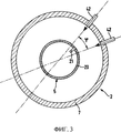
фиг.3 - поперечное сечение плавильного агрегата с внутренней камерой;figure 3 is a cross section of a melting unit with an internal chamber;
фиг.4 - разрез предпочтительного варианта осуществления плавильного агрегата с кольцеобразной камерой сгорания;Fig. 4 is a sectional view of a preferred embodiment of a melting unit with an annular combustion chamber;
фиг.5 - детальный вид фиг.4.figure 5 is a detailed view of figure 4.
Фиг.1 показывает устройство 1 для непрерывного получения стали с применением металлических исходных материалов, например лома. Она состоит из плавильного агрегата 2 и расположенной рядом с ним емкости 3 для нагрева и обработки, т.е. печи, в которой осуществляются нагрев полученного в плавильном агрегате 2 расплава, а также легирование стали. Плавильный агрегат 2 состоит из шахты 4, в которую сверху с газовым уплотнением вводится внутренняя камера 5, не доходящая до нижней части 6, т.е. до дна шахты 4. Таким образом образована кольцевая шахтная печь. Плавильный агрегат 2 далее называется как шахтная печь. В показанном варианте осуществления изобретения стенка 7 шахтной печи, по меньшей мере, в области еще твердого столба скрапа сформирована с расширяющейся книзу конусностью, в то время как внутренняя камера 5 образована с противоположной этой форме конусностью. Благодаря такой расширяющейся конструкции шахтной печи достигается то, что столб 8 материалов, который загружается сверху, может двигаться сверху вниз, заполняя образованное внизу свободное пространство. В области расплава 9, т.е. в нижней трети шахтной печи шахтная печь также может снова быть сформирована цилиндрической или с противоположной конусностью. Противоположная к внутренней камере 5 конусность увеличивает внизу свободное пространство; но внутренняя камера может также быть сформирована цилиндрической.Figure 1 shows a
Шахтная печь через расположенное в нижней части выпускное отверстие 10 и жаропрочное уплотнение соединена с емкостью 3 для обработки. Емкость 3 для обработки в представленном здесь варианте осуществления состоит по существу из нижней части 11 емкости с ванной расплава и верхней части 12 емкости. Для осуществления процесса материал 8 загружается сверху в шахтную печь. Столб материала предварительно нагревается текущими навстречу нагретыми отходящими газами из емкости 3 для обработки и шахтной печи и в нижней части 9 шахтной печи расплавляется посредством горелки 14, которая объединена с концом 15 внутренней камеры 5. Расплав 16 непрерывно вытекает через выпускное отверстие 10 в нижнюю часть 11 ванны с расплавом емкости 3 для обработки. В противоположном направлении из емкости 3 для обработки через отверстие 10 или отдельный газопровод в плавильный агрегат могут протекать отходящие газы.The shaft furnace through the outlet 10 located in the lower part and the heat-resistant seal is connected to the processing tank 3. The processing tank 3 in the embodiment presented here consists essentially of the lower part 11 of the vessel with the molten bath and the upper part 12 of the vessel. To carry out the process, material 8 is loaded from above into a shaft furnace. The material column is preheated by the flowing heated exhaust gases from the processing vessel 3 and the shaft furnace and melted in the lower part 9 of the shaft furnace by means of a
Внутренняя камера 5, которая введена по центру в столб материала 8, имеет в своем полом внутреннем пространстве 17 подводящие трубопроводы 18, 19, а также в своей стенке 20 впускные отверстия 21, чтобы целенаправленно направлять транспортированные сюда через подводящие трубопроводы 18 дожигающие газы или окислители 22 из внутренней камеры 5 в столб материала 8. Впускные отверстия 21 расположены соответственно на размещенных друг над другом уровнях Е1, Е2 поперек продольной оси внутренней камеры 5 и радиально к стенке 20 внутренней камеры и таким образом образуют дожигающие уровни Е1, Е2, которые посредством течения отходящих газов могут несколько увеличиваться. Также для этого может быть размещено несколько отверстий непосредственно друг над другом. Протекающие через материал 8 нагретые отходящие газы 13 дожигаются на соответствующих дожигающих уровнях Е1, Е2 при помощи установленной для соответствующего дожигающего уровня смеси из дожигающих газов 22.The
Дополнительно внутренняя камера 5 на своем обращенном ко дну 6 шахты 4 конце 15 имеет горелку 14 для ископаемого топлива 23, которое подается посредством отдельного подводящего трубопровода 19. Ископаемые энергоносители 23, предпочтительно газ/нефть, которые подаются с окислителями (например, кислородом, воздухом или их смесью) через отдельный трубопровод, смешиваются и дожигаются в горелке. Предпочтительно дожигание ископаемого горючего для плавления материала 8 осуществляется нестехиометрически. Таким образом, остается небольшое количество кислорода, который может ошлаковывать железо.Additionally, the
При подводе обеспечивающих дожигание газов 22, а также необходимого для плавления топлива 23 через внутреннюю камеру 5 они уже предварительно нагреваются. Для увеличения степени предварительного нагрева за пределами внутренней камеры 5 может быть расположен теплообменный агрегат 24, в котором газы или топливо 22, 23 предварительно нагреваются посредством предварительно поданных нагретых отходящих газов 13.When supplying the afterburning
После предварительного нагрева и плавления материала 8 расплав 16 непрерывно передается в емкость 3 для обработки. Емкость 3 для обработки выполнена с возможностью вращения. По завершении обработки стали при вращении емкости вокруг проходящей параллельно основанию 25 поворотной оси 26 через выпускное отверстие 27 в нижнюю часть 11 емкости попадает сначала шлак, а затем расплав стали. К тому же нижняя часть 11 емкости опирается на поворотное устройство 28. Она посредством имеющей возможность передвигаться пластины 25 основания может подводиться к плавильному агрегату 2. У показанного варианта осуществления емкость 3 для обработки сформирована в виде дуговой печи с двумя электродами 29, 30, которые позиционированы на удерживающем устройстве 31 в печи. Кроме того, подвод энергии может осуществляться трехфазным током через три электрода. Необходимая энергия для обработки расплава также может вводиться в форме ископаемого топлива. Емкость 3 для обработки закрывается верхней частью 12 емкости или крышкой. В крышке для осуществления нагрева и вспенивания шлака предусмотрена фурма 32 для ввода углеродсодержащего материала и/или кислорода или воздуха. Кроме того, емкость 3 имеет загрузочное устройство 34 для ввода добавок для металлургической обработки расплава.After preheating and melting the material 8, the melt 16 is continuously transferred to the tank 3 for processing. The processing tank 3 is rotatable. Upon completion of the processing of steel, when the vessel rotates around the rotary axis 26 parallel to the base 25 and passes through the
Позиционирование дожигающих уровней Е1, Е2 относительно плавильного агрегата и вместе с тем дожигающих уровней Е2, Е4, а также свойства выходящих газов 22 устанавливаются или регулируются на соответствующем дожигающем уровне в зависимости от свойств технологических газов по высоте плавильного агрегата. Это представлено на фиг.2. На каждом или на отдельно выбранном дожигающем уровне расположены средства 35 для определения соответствующих свойств технологического газа на соответствующем уровне плавильного агрегата, отбираются пробы газа и передаются дальше или определяются или соответственно измеряются состав и температура нагретых технологических газов. Отобранные на дожигающих уровнях пробы технологического газа могут анализироваться в анализаторе 36а. В зависимости от этих результатов, которые передаются по линии 36 измерения к вычислительному блоку 37, определяются свойства входящих газов 22 для дожигания, и через линии 38 регулирования активизируются соответствующие средства 39 регулировки, которые включают в себя, например, дозирующее и смешивающее устройства для воздуха и кислорода, т.е. распределитель окислительных средств для отдельных дожигающих уровней.The positioning of the afterburning levels E1, E2 relative to the melting unit and, at the same time, afterburning levels E2, E4, as well as the properties of the
На дожигание наряду с регулировкой параметров газов 22 также воздействуют изменением расположения внутренней камеры 5 относительно шахтной печи или изменением месторасположения горелки 14 во внутренней камере 5. Внутренняя камера 5 регулируется посредством передвигающих средств или передвигающего устройства 40 вдоль продольной оси шахтной печи. Кроме того, могут иметься поворотные средства 41, при помощи которых внутренняя камера 5 может поворачиваться вокруг своей продольной оси. Предпочтительно внутренняя камера 5 имеет возможность поворота на угол не менее 0,5φ в зависимости от шахтной печи (фиг.3), чтобы впускные отверстия 21 благоприятно позиционировались во внутренней камере 5 относительно впускных отверстий 42 в стенке 7 шахты. Впускные отверстия 42 дополнительно описываются ниже. Одна или несколько горелок 14 регулируются соответственно внутри внутренней камеры 5 посредством перемещающих устройств 43.In addition to adjusting the parameters of the
Одновременно предусмотрены измерительные устройства 44 для регистрации положения внутренней камеры 5 относительно шахтной печи, а также измерительные устройства 45 для регистрации положения горелки 14 во внутренней камере 5. Кроме того, результаты этих измерений передаются в вычислительный блок 37 и учитываются при установке или регулировке свойств газов 22, 23 для дожигания соответствующим приводом перемещающихся или поворачивающихся средств 40, 41, 43. Они выполняются предпочтительно так, что вне дожигающего уровня или участка достигается локальный перегрев поверхности материала свыше 90% от температуры плавления оксида железа, и степень дожигания выходящих из плавильного ковша отходящих газов составляет приблизительно 100%.At the same time, measuring
Наряду с впускными отверстиями 21 во внутренней камере 5 в стенке 7 плавильного ковша расположены впускные отверстия 42, которые соответственно связаны с подводящими трубопроводами для дожигающих газов 22. При этом образованные впускными отверстиями 21 внутренней камеры или впускными отверстиями 42 стенки агрегата уровни Е1, Е2 или Е3, Е4 соответственно расположены со смещением друг относительно друга так, что соответственно снизу вверх чередуются образованный снаружи дожигающий уровень с впускными отверстиями 42 и образованный внутри дожигающий уровень с впускными отверстиями 21 из внутренней камеры 5. При этом смещение составляет до 50% расстояния между уровнями впускных отверстий. Благодаря такому смещенному расположению предотвращается нагрев отдельных участков столба материала 8, в то время как другие области остаются холодными, так что отсутствует дожигание. Расположение внешних и внутренних впускных отверстий или щелей осуществляется таким образом, что отверстия не мешают друг другу, а их взаимным расположением создается благоприятное газораспределение в столбе материала. Кроме того, фиг.3 поясняется предпочтительное угловое расположение отверстий 21, 42 относительно друг друга. Впускные отверстия 42 в стенке 7 плавильного агрегата 2 располагаются относительно выполненных во внутренней камере 5 впускных отверстий 21 с угловым смещением до 0,5φ, предпочтительно 0,5φ, причем φ - это угол между двумя расположенными рядом друг с другом впускными отверстиями 42 на одном дожигающем уровне.Along with the
Согласно особенно предпочтительному варианту осуществления, который поясняется фиг.4 и 5, стенка 107 шахтной печи на уровне впускных отверстий 142 снабжена кольцевой промежуточной камерой или камерой 146 сгорания.According to a particularly preferred embodiment, which is illustrated in FIGS. 4 and 5, the
Эта камера 146 сгорания в показанном варианте осуществления состоит из выступающего наружу отворота 147 стенки 107 ковша, причем внутреннее пространство камеры сгорания отделено проходящей за внутреннюю сторону 148 стенки 7 шахты промежуточной стенкой 149 от внутреннего пространства шахтной печи и вместе с тем от столба материала 8. При этом промежуточная стенка 149 позиционирована в камере 146 сгорания так, что внизу возникает впускная область 150 для протекающих технологических газов 113, а выше выпускная область 151 для протекающих технологических газов 113'. Таким образом, достигается циркуляция технологических газов 113 через камеру 146 сгорания или промежуточную камеру, и дожигание осуществляется большей частью в этом камере 146. На фиг.5 показано расположение впускных отверстий 142 в стенке 107 шахтной печи относительно промежуточной стенки 149. Образуемый входом впускных отверстий 142 или щелей угол α между продолжениями прямых от входа к промежуточной стенке 149 может принимать значения между 90° и -90°. Предпочтительно угол задается так, что имеет место захватывающий эффект для втекающего технологического газа. Впускное отверстие 142 может быть выполнено в виде сопла Лаваля, т.е. сопла, которое сужается, а затем снова расширяется для достижения ускорения газов.This
В целом предложенный способ или устройство предоставляют эффективную возможность производства стали с использованием ископаемых энергоносителей, а следовательно, также представляет интерес для мест применения, которые плохо обеспечиваются электрической энергией.In General, the proposed method or device provides an effective opportunity for the production of steel using fossil energy, and therefore, is also of interest for applications that are poorly supplied with electric energy.
Claims (25)
Applications Claiming Priority (2)
| Application Number | Priority Date | Filing Date | Title |
|---|---|---|---|
| DE10205660A DE10205660B4 (en) | 2002-02-12 | 2002-02-12 | Process and apparatus for continuous steelmaking using metallic feedstock |
| DE10205660.9 | 2002-02-12 |
Publications (2)
| Publication Number | Publication Date |
|---|---|
| RU2004127233A RU2004127233A (en) | 2005-05-10 |
| RU2301835C2 true RU2301835C2 (en) | 2007-06-27 |
Family
ID=27588547
Family Applications (1)
| Application Number | Title | Priority Date | Filing Date |
|---|---|---|---|
| RU2004127233/02A RU2301835C2 (en) | 2002-02-12 | 2003-01-09 | Method and device for continuous production of steel with the use of starting metal material |
Country Status (12)
| Country | Link |
|---|---|
| US (2) | US7897100B2 (en) |
| EP (1) | EP1481101B1 (en) |
| JP (1) | JP4481653B2 (en) |
| KR (1) | KR100950236B1 (en) |
| CN (1) | CN1303224C (en) |
| AT (1) | ATE439455T1 (en) |
| AU (1) | AU2003208320A1 (en) |
| DE (2) | DE10205660B4 (en) |
| RU (1) | RU2301835C2 (en) |
| TW (1) | TWI282819B (en) |
| UA (1) | UA76588C2 (en) |
| WO (1) | WO2003068995A1 (en) |
Cited By (4)
| Publication number | Priority date | Publication date | Assignee | Title |
|---|---|---|---|---|
| WO2014035276A1 (en) * | 2012-08-28 | 2014-03-06 | Общество С Ограниченной Ответственностью Промышленная Компания "Технология Металлов" | Method and apparatus for producing metal from materials containing iron oxides |
| RU2556660C2 (en) * | 2011-02-23 | 2015-07-10 | Сгл Карбон Се | Method of processing of spent carbon containing material of cathode |
| RU2760199C1 (en) * | 2020-12-30 | 2021-11-22 | федеральное государственное бюджетное образовательное учреждение высшего образования "Национальный исследовательский университет "МЭИ" (ФГБОУ ВО "НИУ "МЭИ") | Continuous steel production unit |
| RU2815145C1 (en) * | 2023-06-28 | 2024-03-11 | федеральное государственное бюджетное образовательное учреждение высшего образования "Национальный исследовательский университет "МЭИ" (ФГБОУ ВО "НИУ "МЭИ") | Iron reduction unit |
Families Citing this family (11)
| Publication number | Priority date | Publication date | Assignee | Title |
|---|---|---|---|---|
| DE10205660B4 (en) * | 2002-02-12 | 2010-11-25 | Sms Siemag Aktiengesellschaft | Process and apparatus for continuous steelmaking using metallic feedstock |
| DE102004046727A1 (en) | 2004-09-25 | 2006-04-06 | Sms Demag Ag | Method and device for producing liquid steel |
| DE102004046728A1 (en) * | 2004-09-25 | 2006-04-06 | Sms Demag Ag | Method and device for producing liquid steel |
| DE102004058492A1 (en) * | 2004-12-04 | 2006-06-14 | Sms Demag Ag | Process and plant for secondary steel production based on scrap |
| DE102005028158A1 (en) * | 2005-06-17 | 2006-12-28 | Sms Demag Ag | Process and shaft furnace for the thermal treatment of residues such as scrap |
| DE102007016018A1 (en) * | 2007-04-03 | 2008-10-09 | Sms Demag Ag | burner arrangement |
| JP5574468B2 (en) * | 2009-04-16 | 2014-08-20 | 株式会社木下製作所 | Cast iron refining method and refining apparatus |
| US20120107759A1 (en) * | 2010-10-27 | 2012-05-03 | Christopher Moran | Flameless impingement preheating furnace |
| CN102563858B (en) * | 2012-01-13 | 2013-12-25 | 云南泛亚能源科技有限公司 | Complementary combustion device for low temperature waste heat power generation |
| AT513281B1 (en) * | 2013-02-19 | 2014-03-15 | Seirlehner Leopold Dipl Ing | Method and device for the continuous production of molten steel molten scrap |
| CN116712935B (en) * | 2023-08-08 | 2023-11-28 | 福建优力特材料科技有限公司 | Melting pot double-way pretreatment feeding device and feeding method for nitrous oxide preparation |
Family Cites Families (16)
| Publication number | Priority date | Publication date | Assignee | Title |
|---|---|---|---|---|
| DE101952C (en) | ||||
| FR1335004A (en) * | 1962-06-09 | 1963-08-16 | Snecma | Non-homogeneous flow gas generator |
| DE1433431B2 (en) * | 1963-10-29 | 1971-12-16 | Fried Krupp GmbH, 4300 Essen | MELTING FURNACE FOR THE PRODUCTION OF STEEL AND METHOD OF OPERATING THE FURNACE |
| JPS5143015B2 (en) * | 1972-05-04 | 1976-11-19 | ||
| US4120696A (en) * | 1973-05-19 | 1978-10-17 | Klockner-Werke Ag | Process for the production of steel |
| DE2325593C2 (en) * | 1973-05-19 | 1975-03-27 | Kloeckner-Werke Ag, 4100 Duisburg | Continuous steel production |
| DE2342959B1 (en) * | 1973-08-25 | 1975-02-13 | Kloeckner Werke Ag | Device for the continuous production of steel from ore |
| DE8437922U1 (en) * | 1984-12-22 | 1987-10-29 | Kortec AG, Zug | Device for heating charging material |
| DE3735150A1 (en) * | 1987-10-16 | 1989-05-03 | Kortec Ag | METHOD FOR SUPPLYING HEATING ENERGY INTO A METAL MELT |
| SE462630B (en) * | 1988-03-16 | 1990-07-30 | Flaekt Ab | PROCEDURE AND DEVICE FOR RECOVERY OF ENERGY IN METALLURGICAL PROCESSES |
| US5286277A (en) * | 1992-05-26 | 1994-02-15 | Zaptech Corporation | Method for producing steel |
| US5885323A (en) * | 1997-04-25 | 1999-03-23 | Ltv Steel Company, Inc. | Foamy slag process using multi-circuit lance |
| DE19753184A1 (en) * | 1997-11-21 | 1999-06-10 | Mannesmann Ag | Melting furnace plant |
| DE19755890A1 (en) * | 1997-12-05 | 1999-06-17 | Mannesmann Ag | Feeding device for shaft furnaces |
| IT1310768B1 (en) * | 1999-09-06 | 2002-02-22 | Danieli Off Mecc | OVEN FOR THE DIRECT REDUCTION OF IRON OXIDES |
| DE10205660B4 (en) * | 2002-02-12 | 2010-11-25 | Sms Siemag Aktiengesellschaft | Process and apparatus for continuous steelmaking using metallic feedstock |
-
2002
- 2002-02-12 DE DE10205660A patent/DE10205660B4/en not_active Expired - Fee Related
- 2002-12-31 TW TW091137993A patent/TWI282819B/en not_active IP Right Cessation
-
2003
- 2003-01-09 KR KR1020047007504A patent/KR100950236B1/en active IP Right Grant
- 2003-01-09 JP JP2003568106A patent/JP4481653B2/en not_active Expired - Lifetime
- 2003-01-09 WO PCT/EP2003/000123 patent/WO2003068995A1/en active Application Filing
- 2003-01-09 EP EP03706351A patent/EP1481101B1/en not_active Expired - Lifetime
- 2003-01-09 AT AT03706351T patent/ATE439455T1/en active
- 2003-01-09 US US10/498,632 patent/US7897100B2/en active Active
- 2003-01-09 DE DE50311806T patent/DE50311806D1/en not_active Expired - Lifetime
- 2003-01-09 AU AU2003208320A patent/AU2003208320A1/en not_active Abandoned
- 2003-01-09 CN CNB038037912A patent/CN1303224C/en not_active Expired - Lifetime
- 2003-01-09 RU RU2004127233/02A patent/RU2301835C2/en active
- 2003-09-01 UA UA20040907420A patent/UA76588C2/en unknown
-
2011
- 2011-02-11 US US13/025,856 patent/US8172922B2/en not_active Expired - Fee Related
Cited By (5)
| Publication number | Priority date | Publication date | Assignee | Title |
|---|---|---|---|---|
| RU2556660C2 (en) * | 2011-02-23 | 2015-07-10 | Сгл Карбон Се | Method of processing of spent carbon containing material of cathode |
| WO2014035276A1 (en) * | 2012-08-28 | 2014-03-06 | Общество С Ограниченной Ответственностью Промышленная Компания "Технология Металлов" | Method and apparatus for producing metal from materials containing iron oxides |
| RU2760199C1 (en) * | 2020-12-30 | 2021-11-22 | федеральное государственное бюджетное образовательное учреждение высшего образования "Национальный исследовательский университет "МЭИ" (ФГБОУ ВО "НИУ "МЭИ") | Continuous steel production unit |
| RU2760199C9 (en) * | 2020-12-30 | 2021-12-21 | федеральное государственное бюджетное образовательное учреждение высшего образования "Национальный исследовательский университет "МЭИ" (ФГБОУ ВО "НИУ "МЭИ") | Continuous steel production unit |
| RU2815145C1 (en) * | 2023-06-28 | 2024-03-11 | федеральное государственное бюджетное образовательное учреждение высшего образования "Национальный исследовательский университет "МЭИ" (ФГБОУ ВО "НИУ "МЭИ") | Iron reduction unit |
Also Published As
| Publication number | Publication date |
|---|---|
| DE50311806D1 (en) | 2009-09-24 |
| KR100950236B1 (en) | 2010-03-29 |
| US20050155457A1 (en) | 2005-07-21 |
| CN1303224C (en) | 2007-03-07 |
| US20110126672A1 (en) | 2011-06-02 |
| US7897100B2 (en) | 2011-03-01 |
| RU2004127233A (en) | 2005-05-10 |
| ATE439455T1 (en) | 2009-08-15 |
| WO2003068995A1 (en) | 2003-08-21 |
| AU2003208320A1 (en) | 2003-09-04 |
| CN1633508A (en) | 2005-06-29 |
| TWI282819B (en) | 2007-06-21 |
| EP1481101B1 (en) | 2009-08-12 |
| DE10205660B4 (en) | 2010-11-25 |
| JP4481653B2 (en) | 2010-06-16 |
| US8172922B2 (en) | 2012-05-08 |
| TW200303923A (en) | 2003-09-16 |
| DE10205660A1 (en) | 2003-08-14 |
| JP2005517806A (en) | 2005-06-16 |
| UA76588C2 (en) | 2006-08-15 |
| EP1481101A1 (en) | 2004-12-01 |
| KR20040074987A (en) | 2004-08-26 |
Similar Documents
| Publication | Publication Date | Title |
|---|---|---|
| US8172922B2 (en) | Method and device for the continuous production of steel using metal charge material | |
| US4203761A (en) | Process of smelting with submerged burner | |
| KR960004796B1 (en) | Arc type steel-making electric furnace and steel-making process | |
| KR0140022B1 (en) | Electric arc furnace with alternative sources of energy and operating method for such electric furnace | |
| JP2005517806A5 (en) | ||
| RU2220392C2 (en) | Industrial melting furnace, metallurgical melting vessel and methods of their employment | |
| ES2947382T3 (en) | Oxygen-fuel combustion system for melting a pelletized feedstock | |
| RU2210601C2 (en) | Method of reduction and melting of metal | |
| RU2360010C2 (en) | Stove unit and melting method of metallic or metal-bearing raw materials | |
| JP2001526318A (en) | Method for producing direct reduced iron in multistage furnaces | |
| US5066326A (en) | Gas-fired steelmelting process | |
| JP7105381B2 (en) | Method and shaft furnace for burning carbon-containing materials in a shaft furnace | |
| RU2295574C2 (en) | Method of production of metal and plant for realization of this method | |
| RU2645858C2 (en) | Electric steel melting unit ladle-furnace (esu-lf) | |
| EP1226283B1 (en) | High temperature premelting apparatus | |
| US3964897A (en) | Method and arrangement for melting charges, particularly for use in the production of steel | |
| US4981285A (en) | Gas-fired steelmelting apparatus | |
| JP3650193B2 (en) | Method for melting metal raw materials | |
| AU662372B2 (en) | An electric arc furnace arrangement for producing steel | |
| JPH0979754A (en) | Continuous melting furnace | |
| EP0040285A1 (en) | Metallurgical process and furnace | |
| AU2004276428A1 (en) | Industrial oven | |
| CA1154270A (en) | Process of smelting with submerged burner | |
| CZ20032954A3 (en) | Process for producing liquid steel from solid charge and apparatus for making the same | |
| WO1981003342A1 (en) | Metallurgical process and furnace |