RU2301373C1 - Steam generator module - Google Patents
Steam generator module Download PDFInfo
- Publication number
- RU2301373C1 RU2301373C1 RU2006103880/06A RU2006103880A RU2301373C1 RU 2301373 C1 RU2301373 C1 RU 2301373C1 RU 2006103880/06 A RU2006103880/06 A RU 2006103880/06A RU 2006103880 A RU2006103880 A RU 2006103880A RU 2301373 C1 RU2301373 C1 RU 2301373C1
- Authority
- RU
- Russia
- Prior art keywords
- diameter
- chamber
- working fluid
- tube
- steam generator
- Prior art date
Links
- 239000012530 fluid Substances 0.000 claims abstract description 32
- 230000002093 peripheral effect Effects 0.000 claims abstract description 12
- 125000006850 spacer group Chemical group 0.000 claims description 12
- 238000007599 discharging Methods 0.000 abstract 3
- 230000000694 effects Effects 0.000 abstract 1
- 239000000126 substance Substances 0.000 abstract 1
- 238000009827 uniform distribution Methods 0.000 description 2
- XLYOFNOQVPJJNP-UHFFFAOYSA-N water Substances O XLYOFNOQVPJJNP-UHFFFAOYSA-N 0.000 description 2
- 238000009434 installation Methods 0.000 description 1
- 239000000203 mixture Substances 0.000 description 1
Images
Landscapes
- Heat-Exchange Devices With Radiators And Conduit Assemblies (AREA)
Abstract
Description
Изобретение относится к конструкционным элементам теплообменных аппаратов.The invention relates to structural elements of heat exchangers.
Известен модуль парогенератора, трубный пучок которого набран из труб Фильда, содержащий камеру входа котловой воды (рабочего тела), камеру выхода пароводяной смеси (рабочего тела), трубные доски и дистанционирующие решетки (Концептуальный проект АЭС с двумя блоками мощностью 1600 МВт каждый на базе РУ типа СВБР-75/100, пояснительная записка, книга 2, установка реакторная СВБР-75/100, SVR.0 UJA.0.TH.PZ.KCP, 461 ПЗ, Листы 51-53, 2001 г. - прототип).A well-known steam generator module, the tube bundle of which is drawn from the Field pipes, containing a boiler water inlet (working fluid) chamber, a steam-water mixture outlet chamber (working fluid), tube boards and spacer grids (A conceptual design of a nuclear power plant with two 1600 MW units each based on a switchgear type SVBR-75/100, explanatory note, book 2, reactor installation SVBR-75/100, SVR.0 UJA.0.TH.PZ.KCP, 461 ПЗ, Sheets 51-53, 2001 - prototype).
Недостатком этого модуля парогенератора является то, что внутренние трубы в пределах камеры выхода рабочего тела имеют низкую вибрационную прочность, кроме этого не обеспечивается равномерное распределение рабочего тела по высоте камеры выхода.The disadvantage of this module of the steam generator is that the inner pipes within the outlet chamber of the working fluid have low vibrational strength, in addition, the uniform distribution of the working fluid along the height of the outlet chamber is not ensured.
Задача изобретения - повышение надежности модуля парогенератора.The objective of the invention is to increase the reliability of the steam generator module.
Техническим результатом предлагаемого изобретения является увеличение жесткости внутренних труб трубного пучка в пределах камеры выхода рабочего тела, а также достижение равномерной раздачи рабочего тела по высоте камеры выхода рабочего тела модуля парогенератора.The technical result of the invention is to increase the rigidity of the inner tubes of the tube bundle within the outlet chamber of the working fluid, as well as to achieve uniform distribution of the working fluid along the height of the outlet chamber of the working fluid of the steam generator module.
Указанный результат достигается тем, что модуль парогенератора, содержащий корпус, камеру входа рабочего тела, камеру выхода рабочего тела, трубный пучок из труб Фильда, верхнюю и нижнюю трубные доски, причем над нижней трубной доской, в камере выхода рабочего тела, установлена дистанционирующая решетка с юбкой в периферийной части, выполненная, по крайней мере, для одного ряда внутренних труб в виде кольца, при этом внутренние трубы выше дистанционирующей решетки до верхней трубной доски выполнены большего диаметра, чем диаметр внутренних труб, а внутренние трубы в периферийной части, проходящие сквозь кольцо, в пределах выходной камеры по высоте выполнены с переменным диаметром от большего диаметра, чем диаметр внутренней трубы, до наружного диаметра внутренней трубы.This result is achieved by the fact that the steam generator module, comprising a housing, a working fluid inlet chamber, a working fluid outlet chamber, a tube bundle from the Field pipes, an upper and lower tube boards, and a spacer grid with a spacer grid is installed above the lower tube plate in the working chamber exit chamber a skirt in the peripheral part, made for at least one row of inner pipes in the form of a ring, while the inner pipes above the spacer grid to the upper tube plate are made of a larger diameter than the diameter of the inner x pipe and the inner pipe in the peripheral portion extending through the ring, within the variable diameter of the output adjustment executed by the chamber of larger diameter than the diameter of the inner tube, the outer diameter of the inner tube.
Камера, образованная юбкой дистанционирующей решетки и внутренними трубами большего диаметра, чем диаметр внутренних труб, создает условия для перемешивания потоков рабочего тела и выравнивания полей скоростей на входе в камеру выхода рабочего тела модуля парогенератора.The chamber formed by the skirt of the spacer grid and the inner pipes of a larger diameter than the diameter of the inner tubes creates the conditions for mixing the flows of the working fluid and aligning the velocity fields at the entrance to the exit chamber of the working fluid of the steam generator module.
Наличие большего диаметра внутренних труб трубного пучка создает им необходимую жесткость в условиях поперечного обтекания потоком рабочего тела.The presence of a larger diameter of the inner tubes of the tube bundle creates the necessary rigidity for them in the conditions of transverse flow around the working fluid.
Переменный диаметр периферийных внутренних труб по высоте камеры выхода рабочего тела способствует равномерному заполнению рабочим телом камеры выхода от нижней трубной доски до верхней и, как следствие, способствует равномерному выходу рабочего тела из трубного пучка в выходную камеру.The variable diameter of the peripheral inner tubes along the height of the outlet chamber of the working fluid contributes to the uniform filling of the outlet chamber by the working fluid from the lower tube plate to the upper one and, as a result, contributes to the uniform exit of the working fluid from the tube bundle to the outlet chamber.
Сущность предлагаемого изобретения поясняется чертежами, гдеThe essence of the invention is illustrated by drawings, where
на фиг.1 изображен продольный разрез модуля парогенератора;figure 1 shows a longitudinal section of a module of a steam generator;
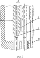
на фиг.2 изображен разрез по внутренним и наружным трубам трубного пучка.figure 2 shows a section along the inner and outer tubes of the tube bundle.
Модуль парогенератора содержит корпус 1, камеру 2 входа рабочего тела, камеру 3 выхода рабочего тела, верхнюю трубную доску 4, нижнюю трубную доску 5, периферийные внутренние трубы 6, внутренние трубы 7, дистанционирующую решетку 8, юбку 9 и наружные трубы 10 трубного пучка.The steam generator module comprises a housing 1, a working fluid inlet chamber 2, a working fluid outlet chamber 3, an upper tube plate 4, a lower tube plate 5, peripheral inner tubes 6, inner tubes 7, a spacer grid 8, a skirt 9 and
Дистанционирующая решетка 8 представляет собой в периферийной части кольцо с отверстиями для прохода, по крайней мере, одного ряда периферийных внутренних труб 6, а в средней части - дистанционирующие планки (не показано) для крепления внутренних труб 7. Юбка 9 дистанционирующей решетки 8 и увеличенные диаметры внутренних труб 7 образуют камеру, в которой создаются условия для перемешивания потоков рабочего тела и выравнивания полей скоростей на входе в выходную камеру 3 рабочего тела модуля парогенератора.The spacer grid 8 is in the peripheral part a ring with holes for the passage of at least one row of peripheral inner tubes 6, and in the middle part, spacer bars (not shown) for attaching the inner tubes 7. Skirt 9 of the spacer grid 8 and larger diameters inner pipes 7 form a chamber in which conditions are created for mixing the flows of the working fluid and alignment of the velocity fields at the entrance to the output chamber 3 of the working fluid of the steam generator module.
Модуль парогенератора работает следующим образом.The steam generator module operates as follows.
Рабочее тело подается в камеру 2 корпуса 1 модуля парогенератора, далее по внутренним полостям периферийных внутренних 6 и внутренних труб 7 труб трубного пучка Фильда подается в кольцевой зазор между наружными трубами 10 и периферийными внутренними 6 и внутренними трубами 7. Из кольцевого зазора рабочее тело поступает в камеру, образованную юбкой 9 дистанционирующей решетки 8 и увеличенными диаметрами внутренних труб 7. В камере происходит перемешивание рабочего тела и выравнивание полей скоростей.The working fluid is fed into the chamber 2 of the housing 1 of the steam generator module, then through the internal cavities of the peripheral inner 6 and inner tubes 7 of the tube bundle of the Field tube is fed into the annular gap between the
Наличие переменного диаметра по высоте камеры выхода рабочего тела периферийных внутренних труб 6 создает условия для равномерного заполнения рабочим телом пространства от нижней трубной доски 5 до верхней трубной доски 4 и, как следствие, обеспечивает равномерный выход рабочего тела из камеры выхода 3 рабочего тела.The presence of a variable diameter along the height of the outlet chamber of the working fluid of the peripheral inner tubes 6 creates conditions for uniformly filling the working fluid of the space from the lower tube plate 5 to the upper tube plate 4 and, as a result, provides a uniform exit of the working fluid from the outlet chamber 3 of the working fluid.
Claims (1)
Priority Applications (1)
| Application Number | Priority Date | Filing Date | Title |
|---|---|---|---|
| RU2006103880/06A RU2301373C1 (en) | 2006-02-10 | 2006-02-10 | Steam generator module |
Applications Claiming Priority (1)
| Application Number | Priority Date | Filing Date | Title |
|---|---|---|---|
| RU2006103880/06A RU2301373C1 (en) | 2006-02-10 | 2006-02-10 | Steam generator module |
Publications (1)
| Publication Number | Publication Date |
|---|---|
| RU2301373C1 true RU2301373C1 (en) | 2007-06-20 |
Family
ID=38314393
Family Applications (1)
| Application Number | Title | Priority Date | Filing Date |
|---|---|---|---|
| RU2006103880/06A RU2301373C1 (en) | 2006-02-10 | 2006-02-10 | Steam generator module |
Country Status (1)
| Country | Link |
|---|---|
| RU (1) | RU2301373C1 (en) |
Cited By (1)
| Publication number | Priority date | Publication date | Assignee | Title |
|---|---|---|---|---|
| RU2540207C1 (en) * | 2014-01-28 | 2015-02-10 | Открытое акционерное общество "Всероссийский научно-исследовательский институт по эксплуатации атомных электростанций" (ОАО "ВНИИАЭС") | Steam generator |
Citations (3)
| Publication number | Priority date | Publication date | Assignee | Title |
|---|---|---|---|---|
| DE3411795A1 (en) * | 1984-03-30 | 1985-10-03 | Borsig Gmbh, 1000 Berlin | METHOD FOR OPERATING TUBE BUNDLE HEAT EXCHANGERS FOR COOLING GASES |
| RU2140608C1 (en) * | 1998-04-13 | 1999-10-27 | Дмитриев Сергей Михайлович | Once-through vertical steam generator |
| RU2258176C1 (en) * | 2004-03-04 | 2005-08-10 | ЗАО "Научно-производственное объединение "Гидропресс" | Steam generator with liquid metal coolant |
-
2006
- 2006-02-10 RU RU2006103880/06A patent/RU2301373C1/en active IP Right Revival
Patent Citations (3)
| Publication number | Priority date | Publication date | Assignee | Title |
|---|---|---|---|---|
| DE3411795A1 (en) * | 1984-03-30 | 1985-10-03 | Borsig Gmbh, 1000 Berlin | METHOD FOR OPERATING TUBE BUNDLE HEAT EXCHANGERS FOR COOLING GASES |
| RU2140608C1 (en) * | 1998-04-13 | 1999-10-27 | Дмитриев Сергей Михайлович | Once-through vertical steam generator |
| RU2258176C1 (en) * | 2004-03-04 | 2005-08-10 | ЗАО "Научно-производственное объединение "Гидропресс" | Steam generator with liquid metal coolant |
Cited By (1)
| Publication number | Priority date | Publication date | Assignee | Title |
|---|---|---|---|---|
| RU2540207C1 (en) * | 2014-01-28 | 2015-02-10 | Открытое акционерное общество "Всероссийский научно-исследовательский институт по эксплуатации атомных электростанций" (ОАО "ВНИИАЭС") | Steam generator |
Similar Documents
| Publication | Publication Date | Title |
|---|---|---|
| CN103047882A (en) | Wave tube baffle grid square heat exchanger | |
| RU2583321C1 (en) | Steam generator with horizontal beam of heat exchange pipes and assembly method thereof | |
| US7204301B2 (en) | Multiservice heat exchange unit | |
| RU2011113827A (en) | EXHAUST HEAT STEAM GENERATOR | |
| KR20110128849A (en) | Continuous Flow Evaporator | |
| CN85108386A (en) | Heat exchanger tube bundle protection | |
| RU2011113816A (en) | FLOW TYPE STEAM GENERATOR | |
| RU2010121716A (en) | HORIZONTAL REACTOR FOR THE REACTION OF EXCHANGE OF A LIQUID FLOW OF THE SOURCE WITH A LIQUID FLOW OF AN OXIDATOR IN THE PRESENCE OF A SOLID CATALYST | |
| RU2301373C1 (en) | Steam generator module | |
| KR20100118937A (en) | Tube support structure | |
| CN212962949U (en) | Plate-shell type heat exchanger with baffling structure | |
| CN103216814B (en) | Method and device for implementing uniform flow of steam in boiler barrel | |
| RU2482906C2 (en) | Hydrodynamic method of making water-fuel emulsion and hydrodynamic cavitation reactor | |
| US4173997A (en) | Modular steam generator | |
| CN106322338A (en) | Steam generator with side water supply function | |
| CN103471082A (en) | Three-section horizontal type feed water heater for 200MW units | |
| US5329886A (en) | Steam generator | |
| EP3521700B1 (en) | Steam superheater | |
| US10049775B2 (en) | Steam separation system and nuclear boiling water reactor including the same | |
| CN205965792U (en) | Gas heat exchange type isothermal reactor | |
| RU2341750C1 (en) | Heat exchanger | |
| RU2390690C1 (en) | Throttle | |
| CN216667632U (en) | Integrated sleeve type steam-water circulating device | |
| JP2003004885A (en) | Steam generator | |
| CN119958313B (en) | Shell-and-tube heat exchanger for vapor-liquid mixed heat exchange and heat exchange method thereof |
Legal Events
| Date | Code | Title | Description |
|---|---|---|---|
| HK4A | Changes in a published invention | ||
| PC41 | Official registration of the transfer of exclusive right |
Effective date: 20121008 |
|
| QB4A | Licence on use of patent |
Free format text: LICENCE Effective date: 20130307 |
|
| NF4A | Reinstatement of patent |
Effective date: 20151110 |