RU2301173C2 - System and method of stopping the electric motor of propulsion plant - Google Patents
System and method of stopping the electric motor of propulsion plant Download PDFInfo
- Publication number
- RU2301173C2 RU2301173C2 RU2004130854/09A RU2004130854A RU2301173C2 RU 2301173 C2 RU2301173 C2 RU 2301173C2 RU 2004130854/09 A RU2004130854/09 A RU 2004130854/09A RU 2004130854 A RU2004130854 A RU 2004130854A RU 2301173 C2 RU2301173 C2 RU 2301173C2
- Authority
- RU
- Russia
- Prior art keywords
- motor
- propeller
- shorting
- modules
- stator windings
- Prior art date
Links
Images

Classifications
-
- B—PERFORMING OPERATIONS; TRANSPORTING
- B63—SHIPS OR OTHER WATERBORNE VESSELS; RELATED EQUIPMENT
- B63H—MARINE PROPULSION OR STEERING
- B63H23/00—Transmitting power from propulsion power plant to propulsive elements
- B63H23/22—Transmitting power from propulsion power plant to propulsive elements with non-mechanical gearing
- B63H23/24—Transmitting power from propulsion power plant to propulsive elements with non-mechanical gearing electric
-
- B—PERFORMING OPERATIONS; TRANSPORTING
- B60—VEHICLES IN GENERAL
- B60L—PROPULSION OF ELECTRICALLY-PROPELLED VEHICLES; SUPPLYING ELECTRIC POWER FOR AUXILIARY EQUIPMENT OF ELECTRICALLY-PROPELLED VEHICLES; ELECTRODYNAMIC BRAKE SYSTEMS FOR VEHICLES IN GENERAL; MAGNETIC SUSPENSION OR LEVITATION FOR VEHICLES; MONITORING OPERATING VARIABLES OF ELECTRICALLY-PROPELLED VEHICLES; ELECTRIC SAFETY DEVICES FOR ELECTRICALLY-PROPELLED VEHICLES
- B60L15/00—Methods, circuits, or devices for controlling the traction-motor speed of electrically-propelled vehicles
- B60L15/20—Methods, circuits, or devices for controlling the traction-motor speed of electrically-propelled vehicles for control of the vehicle or its driving motor to achieve a desired performance, e.g. speed, torque, programmed variation of speed
-
- B—PERFORMING OPERATIONS; TRANSPORTING
- B60—VEHICLES IN GENERAL
- B60L—PROPULSION OF ELECTRICALLY-PROPELLED VEHICLES; SUPPLYING ELECTRIC POWER FOR AUXILIARY EQUIPMENT OF ELECTRICALLY-PROPELLED VEHICLES; ELECTRODYNAMIC BRAKE SYSTEMS FOR VEHICLES IN GENERAL; MAGNETIC SUSPENSION OR LEVITATION FOR VEHICLES; MONITORING OPERATING VARIABLES OF ELECTRICALLY-PROPELLED VEHICLES; ELECTRIC SAFETY DEVICES FOR ELECTRICALLY-PROPELLED VEHICLES
- B60L50/00—Electric propulsion with power supplied within the vehicle
- B60L50/10—Electric propulsion with power supplied within the vehicle using propulsion power supplied by engine-driven generators, e.g. generators driven by combustion engines
- B60L50/13—Electric propulsion with power supplied within the vehicle using propulsion power supplied by engine-driven generators, e.g. generators driven by combustion engines using AC generators and AC motors
-
- B—PERFORMING OPERATIONS; TRANSPORTING
- B60—VEHICLES IN GENERAL
- B60L—PROPULSION OF ELECTRICALLY-PROPELLED VEHICLES; SUPPLYING ELECTRIC POWER FOR AUXILIARY EQUIPMENT OF ELECTRICALLY-PROPELLED VEHICLES; ELECTRODYNAMIC BRAKE SYSTEMS FOR VEHICLES IN GENERAL; MAGNETIC SUSPENSION OR LEVITATION FOR VEHICLES; MONITORING OPERATING VARIABLES OF ELECTRICALLY-PROPELLED VEHICLES; ELECTRIC SAFETY DEVICES FOR ELECTRICALLY-PROPELLED VEHICLES
- B60L7/00—Electrodynamic brake systems for vehicles in general
- B60L7/003—Dynamic electric braking by short circuiting the motor
-
- B—PERFORMING OPERATIONS; TRANSPORTING
- B63—SHIPS OR OTHER WATERBORNE VESSELS; RELATED EQUIPMENT
- B63H—MARINE PROPULSION OR STEERING
- B63H23/00—Transmitting power from propulsion power plant to propulsive elements
- B63H23/32—Other parts
-
- H—ELECTRICITY
- H02—GENERATION; CONVERSION OR DISTRIBUTION OF ELECTRIC POWER
- H02P—CONTROL OR REGULATION OF ELECTRIC MOTORS, ELECTRIC GENERATORS OR DYNAMO-ELECTRIC CONVERTERS; CONTROLLING TRANSFORMERS, REACTORS OR CHOKE COILS
- H02P3/00—Arrangements for stopping or slowing electric motors, generators, or dynamo-electric converters
- H02P3/06—Arrangements for stopping or slowing electric motors, generators, or dynamo-electric converters for stopping or slowing an individual dynamo-electric motor or dynamo-electric converter
- H02P3/18—Arrangements for stopping or slowing electric motors, generators, or dynamo-electric converters for stopping or slowing an individual dynamo-electric motor or dynamo-electric converter for stopping or slowing an ac motor
- H02P3/22—Arrangements for stopping or slowing electric motors, generators, or dynamo-electric converters for stopping or slowing an individual dynamo-electric motor or dynamo-electric converter for stopping or slowing an ac motor by short-circuit or resistive braking
-
- B—PERFORMING OPERATIONS; TRANSPORTING
- B60—VEHICLES IN GENERAL
- B60L—PROPULSION OF ELECTRICALLY-PROPELLED VEHICLES; SUPPLYING ELECTRIC POWER FOR AUXILIARY EQUIPMENT OF ELECTRICALLY-PROPELLED VEHICLES; ELECTRODYNAMIC BRAKE SYSTEMS FOR VEHICLES IN GENERAL; MAGNETIC SUSPENSION OR LEVITATION FOR VEHICLES; MONITORING OPERATING VARIABLES OF ELECTRICALLY-PROPELLED VEHICLES; ELECTRIC SAFETY DEVICES FOR ELECTRICALLY-PROPELLED VEHICLES
- B60L2200/00—Type of vehicles
- B60L2200/32—Waterborne vessels
-
- Y—GENERAL TAGGING OF NEW TECHNOLOGICAL DEVELOPMENTS; GENERAL TAGGING OF CROSS-SECTIONAL TECHNOLOGIES SPANNING OVER SEVERAL SECTIONS OF THE IPC; TECHNICAL SUBJECTS COVERED BY FORMER USPC CROSS-REFERENCE ART COLLECTIONS [XRACs] AND DIGESTS
- Y02—TECHNOLOGIES OR APPLICATIONS FOR MITIGATION OR ADAPTATION AGAINST CLIMATE CHANGE
- Y02T—CLIMATE CHANGE MITIGATION TECHNOLOGIES RELATED TO TRANSPORTATION
- Y02T10/00—Road transport of goods or passengers
- Y02T10/60—Other road transportation technologies with climate change mitigation effect
- Y02T10/64—Electric machine technologies in electromobility
-
- Y—GENERAL TAGGING OF NEW TECHNOLOGICAL DEVELOPMENTS; GENERAL TAGGING OF CROSS-SECTIONAL TECHNOLOGIES SPANNING OVER SEVERAL SECTIONS OF THE IPC; TECHNICAL SUBJECTS COVERED BY FORMER USPC CROSS-REFERENCE ART COLLECTIONS [XRACs] AND DIGESTS
- Y02—TECHNOLOGIES OR APPLICATIONS FOR MITIGATION OR ADAPTATION AGAINST CLIMATE CHANGE
- Y02T—CLIMATE CHANGE MITIGATION TECHNOLOGIES RELATED TO TRANSPORTATION
- Y02T10/00—Road transport of goods or passengers
- Y02T10/60—Other road transportation technologies with climate change mitigation effect
- Y02T10/70—Energy storage systems for electromobility, e.g. batteries
-
- Y—GENERAL TAGGING OF NEW TECHNOLOGICAL DEVELOPMENTS; GENERAL TAGGING OF CROSS-SECTIONAL TECHNOLOGIES SPANNING OVER SEVERAL SECTIONS OF THE IPC; TECHNICAL SUBJECTS COVERED BY FORMER USPC CROSS-REFERENCE ART COLLECTIONS [XRACs] AND DIGESTS
- Y02—TECHNOLOGIES OR APPLICATIONS FOR MITIGATION OR ADAPTATION AGAINST CLIMATE CHANGE
- Y02T—CLIMATE CHANGE MITIGATION TECHNOLOGIES RELATED TO TRANSPORTATION
- Y02T10/00—Road transport of goods or passengers
- Y02T10/60—Other road transportation technologies with climate change mitigation effect
- Y02T10/7072—Electromobility specific charging systems or methods for batteries, ultracapacitors, supercapacitors or double-layer capacitors
-
- Y—GENERAL TAGGING OF NEW TECHNOLOGICAL DEVELOPMENTS; GENERAL TAGGING OF CROSS-SECTIONAL TECHNOLOGIES SPANNING OVER SEVERAL SECTIONS OF THE IPC; TECHNICAL SUBJECTS COVERED BY FORMER USPC CROSS-REFERENCE ART COLLECTIONS [XRACs] AND DIGESTS
- Y02—TECHNOLOGIES OR APPLICATIONS FOR MITIGATION OR ADAPTATION AGAINST CLIMATE CHANGE
- Y02T—CLIMATE CHANGE MITIGATION TECHNOLOGIES RELATED TO TRANSPORTATION
- Y02T10/00—Road transport of goods or passengers
- Y02T10/60—Other road transportation technologies with climate change mitigation effect
- Y02T10/72—Electric energy management in electromobility
Landscapes
- Engineering & Computer Science (AREA)
- Mechanical Engineering (AREA)
- Power Engineering (AREA)
- Transportation (AREA)
- Chemical & Material Sciences (AREA)
- Combustion & Propulsion (AREA)
- Ocean & Marine Engineering (AREA)
- Stopping Of Electric Motors (AREA)
- Control Of Motors That Do Not Use Commutators (AREA)
- Valve Device For Special Equipments (AREA)
- Regulating Braking Force (AREA)
- Control Of Multiple Motors (AREA)
- Braking Arrangements (AREA)
- Output Control And Ontrol Of Special Type Engine (AREA)
- Dynamo-Electric Clutches, Dynamo-Electric Brakes (AREA)
- Control Of Electric Motors In General (AREA)
- Control Of Ac Motors In General (AREA)
Abstract
Description
Область техники, к которой относится изобретениеFIELD OF THE INVENTION
Настоящее изобретение относится к пропульсивной системе, содержащей пропульсивную установку с гребным винтом и приводом на основе гребного электродвигателя. Изобретение относится также к способу стопорения, т.е. снижения скорости и/или ограничения подвижности привода путем наложения ограничений на положение ротора электродвигателя, входящего в состав пропульсивной установки, или роторов электродвигателей двигательных модулей устройства разворота в пропульсивной системе.The present invention relates to a propulsion system comprising a propulsion system with a propeller and a drive based on a propeller motor. The invention also relates to a locking method, i.e. reducing the speed and / or limiting the mobility of the drive by imposing restrictions on the position of the rotor of the electric motor, which is part of the propulsion system, or the rotors of the electric motors of the motor modules of the reversal device in the propulsion system.
Уровень техникиState of the art
В большинстве традиционных конструкций поступательное движение различных судов (включая пассажирские суда, пассажирские паромы, грузовые суда, баржи, нефтяные танкеры, ледоколы, суда прибрежного плавания, военные корабли и т.д.) обеспечивается созданием тягового или толкающего усилия посредством вращающегося гребного винта или нескольких гребных винтов. Для управления судном по курсу обычно используются отдельные рулевые комплексы.In most traditional designs, the progressive movement of various vessels (including passenger ships, passenger ferries, cargo ships, barges, oil tankers, icebreakers, coastal vessels, warships, etc.) is provided by the creation of traction or pushing force by means of a rotary propeller or several propellers. Separate steering systems are usually used to steer the vessel along the course.
Системы для приведения гребного винта во вращение обычно строятся таким образом, что приводное устройство, связанное с гребным валом, например дизельный двигатель, двигатель, работающий на газообразном топливе, или электродвигатель, устанавливается внутри корпуса судна. С двигателем связан гребной вал, выступающий за пределы корпуса через герметизированное отверстие в корпусе. Сам гребной винт находится на противоположном конце гребного вала, т.е. на том его конце, который выступает из корпуса судна. Гребной вал может быть связан непосредственно с электродвигателем или с передачей (в случае ее использования). В большинстве судов, используемых в качестве надводных транспортных средств, именно описанное техническое решение служит для создания усилия, необходимого для осуществления их перемещения.Systems for driving the propeller into rotation are usually constructed in such a way that a drive device associated with the propeller shaft, such as a diesel engine, a gaseous fuel engine or an electric motor, is installed inside the ship's hull. A propeller shaft extending beyond the housing through a sealed hole in the housing is connected to the engine. The propeller itself is located on the opposite end of the propeller shaft, i.e. on that end that protrudes from the hull. The propeller shaft can be connected directly to the electric motor or to the transmission (if used). In most vessels used as surface vehicles, it is the described technical solution that serves to create the effort necessary to carry out their movement.
Далее со ссылками на прилагаемые чертежи будут описаны технические решения, представляющие уровень техники.Next, with reference to the accompanying drawings will be described technical solutions representing the prior art.
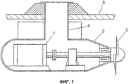
На фиг.1 показана конструкция пропульсивной установки, соответствующей уровню техники.Figure 1 shows the design of the propulsive installation corresponding to the prior art.
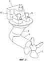
На фиг.2 представлена известная система, содержащая пропульсивную установку с устройством ее разворота.Figure 2 presents a known system containing a propulsion system with a device for its rotation.
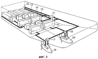
Фиг.3 иллюстрирует известное техническое решение по обеспечению питания пропульсивной системы.Figure 3 illustrates a known technical solution for providing power to a propulsion system.
На фиг.1 изображена пропульсивная установка, соответствующая уровню техники. Известная установка содержит гребной электродвигатель 1, гребной винт 2 и камеру (гондолу) 3, которая присоединена к корпусу 5 судна посредством полого вала 4. В последние годы судостроители приступили к оснащению судов пропульсивными установками подобного типа, в которых гребной электродвигатель, приводящий в движение гребной винт, вместе с передачей любого типа установлен внутри специальной камеры 3, которая расположена вне корпуса 5 судна. При этом камера 3 монтируется с возможностью разворота относительно корпуса 5.Figure 1 shows the propulsive installation corresponding to the prior art. The known installation comprises a
Возможность разворота камеры 3, содержащей гребной электродвигатель 1, относительно корпуса судна обеспечивается с помощью полого вала 4, который проходит сквозь днище судна. Таким образом, пропульсивная установка, способная разворачиваться относительно корпуса 5, может быть использована также вместо отдельного рулевого комплекса для управления судном по курсу. Подобная пропульсивная установка более подробно описана, в частности, в финском патенте №76977, принадлежащем заявителю настоящего изобретения. При этом заявитель предлагает подобные установки, получившие общее название "азимутальных пропульсивных установок" (azimuthing propulsion units), под торговым наименованием AZIPOD®.The possibility of turning the
Было обнаружено, что в дополнение к преимуществам, обеспечиваемым благодаря отказу от длинного гребного вала и отдельного рулевого комплекса, данные установки обеспечивают также значительное улучшение маневренности судна. Оказалось также, что одновременно достигается и экономия энергии. В последние годы использование азимутальных пропульсивных установок на различных надводных судах стало более широким, что объясняется постоянным ростом их популярности.It was found that in addition to the benefits provided by the rejection of a long propeller shaft and a separate steering complex, these installations also provide a significant improvement in ship maneuverability. It also turned out that energy saving was also achieved at the same time. In recent years, the use of azimuthal propulsion systems on various surface ships has become wider, due to the constant increase in their popularity.
На фиг.2 представлена известная пропульсивная система, содержащая пропульсивную установку вместе с устройством ее разворота. Известная пропульсивная система содержит пропульсивную установку (т.е. привод, или двигательный модуль 6 с гребным электродвигателем, гребной винт 7 и несущую секцию 8), кабельный узел 9, а также двигательные модули 10, 11 устройства разворота двигательного модуля. Двигательный модуль 6 и гребной винт 7 пропульсивной установки присоединены к корпусу судна посредством несущей секции 8. Подача электроэнергии, питающей двигательный модуль 6, построенный на основе гребного электродвигателя, обеспечивается с помощью кабельного узла 9. Двигательные модули 10, 11 известного устройства разворота обеспечивают разворот пропульсивной установки через соответствующую зубчатую передачу. Известная пропульсивная система содержит также механические средства стопорения, служащие для уменьшения и/или для ограничения скорости разворота азимутальной пропульсивной установки.Figure 2 presents a known propulsive system containing a propulsive installation together with a device for its rotation. A known propulsive system comprises a propulsive installation (i.e., a drive, or a
На фиг.3 иллюстрируется известная система питания пропульсивной системы. Эта известная система питания содержит двигательные блоки 12, генераторные блоки 13, коммутационные панели 14 сети электропитания, трансформаторные блоки 15 пропульсивной системы, преобразователи 16 частоты для пропульсивных установок, преобразователи 17, 18 частоты для устройств разворота, пропульсивные установки 19, 20 и систему 21 руления.Figure 3 illustrates a known propulsion system power system. This known power supply system comprises
При работе известной системы питания двигательные блоки 12 вырабатывают механическую энергию, преобразуемую генераторными блоками 13 в электрическую энергию, подаваемую на вход сети электропитания. Далее электрическая энергия поступает через коммутационные панели 14 и трансформаторные блоки 15 пропульсивной системы на преобразователи 16 частоты для пропульсивных установок и на преобразователи 17, 18 частоты для устройств разворота. Преобразователи 16-18 частоты подают требуемое напряжение на электродвигатели гребных винтов (гребные электродвигатели) и на устройства разворота пропульсивных установок 19, 20. Функция системы 21 руления заключается в управлении работой устройства разворота.During operation of the known power system, the
Принцип работы преобразователей частоты 16-18 соответствует технологии, известной специалистам в данной области, поэтому в его подробном объяснении нет необходимости. Достаточно только отметить, что основными компонентами преобразователя частоты являются выпрямитель, промежуточный контур постоянного тока и инвертор. В настоящее время преобразователи частоты 16-18 обычно используются в качестве входных устройств электродвигателей переменного тока, причем их применение особенно эффективно в различных регулируемых электроприводах. Наиболее часто используются преобразователи, известные как преобразователи с широтно-импульсной модуляцией (ШИМ-преобразователи), снабженные промежуточными контурами.The principle of operation of frequency converters 16-18 corresponds to the technology known to specialists in this field, so there is no need for its detailed explanation. It is enough to note that the main components of the frequency converter are a rectifier, an intermediate DC circuit and an inverter. Currently, frequency converters 16-18 are usually used as input devices for AC electric motors, and their application is especially effective in various controlled electric drives. The most commonly used converters are known as pulse width modulated converters (PWM converters) equipped with intermediate circuits.
В случае повреждения одного или более гребных винтов судно должно иметь возможность дальнейшего перемещения для осуществления ремонта. Возникающая при этом проблема состоит в том, что при дальнейшем движении судна поврежденный гребной винт может легко перейти во вращение. Это может вызвать дополнительное повреждение пропульсивной установки и, возможно, судна в целом.In the event of damage to one or more propellers, the vessel must be able to move further to carry out repairs. The problem arising in this case is that with further movement of the vessel, the damaged propeller can easily go into rotation. This may cause additional damage to the propulsion system and possibly the ship as a whole.
Аналогично, в случае аварии в системе электропитания электродвигателей в составе устройства разворота пропульсивной установки внезапный разворот этой установки может привести к дополнительным повреждениям пропульсивной установки и, возможно, судна в целом. Если пропульсивная установка сможет бесконтрольно разворачиваться в любом направлении, произойдет значительное ухудшение маневренности судна.Similarly, in the event of an accident in the power supply system of electric motors as part of a device for turning a propulsion system, a sudden turn of this installation can lead to additional damage to the propulsion system and, possibly, the ship as a whole. If the propulsion system can turn uncontrollably in any direction, there will be a significant deterioration in the maneuverability of the vessel.
В качестве известного решения данной проблемы может быть сделана ссылка на патент США №1555244, в котором предлагается система динамического стопорения асинхронного электродвигателя посредством осуществления известным образом короткого замыкания (закорачивания) статорных обмоток. Может быть упомянут также патент США №5184049, в котором предлагается решение задачи уменьшения времени остановки электродвигателя, обслуживающего оптические или магнитные диски, путем подачи на статорные обмотки электродвигателя переменного тока обратного напряжения с последующим закорачиванием этих обмоток. Еще одна ссылка может быть дана на международную заявку WO 97/05691, в которой описано решение задачи управления серводвигателем через ШИМ-преобразователь. Согласно данному решению переключатели преобразователя управляются таким образом, что на период стопорения происходит закорачивание обмоток. В рассмотренных известных решениях асинхронные электродвигатели с короткозамкнутыми роторами не создают никакого вращательного момента при нулевой скорости, поскольку в этом случае в роторах отсутствует вращающееся магнитное поле.As a known solution to this problem, reference can be made to US Pat. No. 1,555,244, which proposes a system for dynamically locking an induction motor by performing a short circuit (short-circuiting) of stator windings. May also be mentioned US patent No. 5184049, which proposes a solution to reduce the stopping time of an electric motor serving optical or magnetic disks by applying reverse voltage to the stator windings of an alternating current electric motor, followed by shorting these windings. Another reference may be given to the international application WO 97/05691, which describes the solution to the problem of controlling a servo motor through a PWM converter. According to this solution, the converter switches are controlled in such a way that the windings are short-circuited for the period of locking. In the known solutions considered, asynchronous motors with squirrel-cage rotors do not create any torque at zero speed, since in this case there is no rotating magnetic field in the rotors.
Применительно к известным пропульсивным установкам были разработаны средства стопорения, основанные на механическом принципе. Задача, решаемая данными средствами стопорения, состоит в том, чтобы предотвратить разворот пропульсивной установки и удерживать пропульсивную установку, по существу, в ее основном (базовом) положении.In relation to known propulsion systems, locking devices based on a mechanical principle have been developed. The problem solved by these locking means is to prevent the propulsion unit from turning and to keep the propulsion unit essentially in its main (basic) position.
Раскрытие изобретенияDisclosure of invention
Задача, на решение которой направлено настоящее изобретение, состоит в том, чтобы устранить недостатки известных решений и разработать новое решение, способное уменьшить и/или ограничить скорость электродвигателя в пропульсивной системе.The problem to which the present invention is directed, is to eliminate the disadvantages of the known solutions and to develop a new solution that can reduce and / or limit the speed of the electric motor in the propulsion system.
Еще одна задача заключается в разработке решения, согласно которому отпадает необходимость в применении какого-либо отдельного механического средства стопорения и, следовательно, устраняются все проблемы, связанные с использованием такого средства.Another task is to develop a solution according to which there is no need to use any separate mechanical means of locking and, therefore, all the problems associated with the use of such means are eliminated.
Следующей задачей, поставленной перед изобретением, является разработка решения, устраняющего необходимость использования какого-либо отдельного механического средства стопорения в случае неуправляемого разворота пропульсивной установки.The next task set for the invention is to develop a solution that eliminates the need to use any separate mechanical locking means in the case of an uncontrolled turn of a propulsion system.
Кроме того, задачей, поставленной перед настоящим изобретением, является разработка решения, позволяющего существенно повысить надежность и экономичность механизмов, служащих для разворота азимутальной пропульсивной установки, по сравнению с решениями, известными из уровня техники.In addition, the task of the present invention is to develop a solution that can significantly improve the reliability and efficiency of the mechanisms used to deploy the azimuthal propulsion system, compared with solutions known from the prior art.
В соответствии с первым аспектом настоящего изобретения предлагается пропульсивная система, обеспечивающая, в частности, уменьшение скорости и/или ограничение подвижности привода на основе гребного электродвигателя пропульсивной установки. Система по изобретению содержит пропульсивную установку с гребным винтом, приводом на основе гребного электродвигателя с постоянными магнитами, преобразователь частоты, подключенный к силовой электрической сети, а также систему для уменьшения скорости и/или ограничения подвижности привода путем наложения ограничений на положение ротора гребного электродвигателя. При этом система по изобретению характеризуется тем, что указанная система для уменьшения скорости и/или ограничения подвижности привода включает в себя переключающее устройство, которое содержит средства для отключения гребного электродвигателя от силовой электрической сети и средства для закорачивания статорных обмоток гребного электродвигателя.In accordance with a first aspect of the present invention, there is provided a propulsion system that provides, in particular, a reduction in speed and / or limitation of the mobility of a drive based on a propulsion motor of a propulsion system. The system according to the invention comprises a propulsion system with a propeller, a drive based on a propeller motor with permanent magnets, a frequency converter connected to the power mains, and also a system for reducing the speed and / or limiting the mobility of the drive by imposing restrictions on the position of the rotor of the propeller motor. Moreover, the system according to the invention is characterized in that said system for reducing the speed and / or limiting the mobility of the drive includes a switching device that includes means for disconnecting the propeller motor from the power mains and means for shorting the stator windings of the propeller motor.
В соответствии с предпочтительным вариантом при установлении необходимости в стопорении гребного электродвигателя обеспечивается возможность его отключения от силовой электрической сети с последующим закорачиванием его статорных обмоток. В альтернативном варианте при установлении необходимости в стопорении гребного электродвигателя он отключается от силовой электрической сети с последующим закорачиванием его статорных обмоток через преобразователь частоты. При этом желательно осуществить такое закорачивание посредством полупроводников.In accordance with the preferred embodiment, when establishing the need for locking the propeller motor, it is possible to disconnect it from the power electric network with the subsequent shorting of its stator windings. In an alternative embodiment, when it becomes necessary to lock the propeller motor, it is disconnected from the power electric network with the subsequent shorting of its stator windings through the frequency converter. In this case, it is desirable to carry out such shorting by means of semiconductors.
Кроме того, желательно, чтобы при закорачивании статорных обмоток гребного электродвигателя они одновременно подключались к контуру заземления оборудования. Переключающее устройство предпочтительно выполняется управляемым посредством секции управления преобразователя частоты.In addition, it is desirable that when shorting the stator windings of the propeller motor, they are simultaneously connected to the equipment ground loop. The switching device is preferably controlled via the control section of the frequency converter.
В качестве гребного электродвигателя пропульсивной установки целесообразно использовать синхронный электродвигатель. При этом система стопорения выполнена с возможностью стопорения более чем одной пропульсивной установки.It is advisable to use a synchronous electric motor as a propulsion motor of a propulsion system. Moreover, the locking system is configured to lock more than one propulsive installation.
В соответствии со вторым аспектом настоящего изобретения предлагается альтернативная пропульсивная система, обеспечивающая уменьшение скорости и/или ограничение подвижности электродвигателя пропульсивной установки. Система по изобретению содержит пропульсивную установку с гребным винтом и с приводом на основе гребного электродвигателя и устройство разворота с двигательными модулями на базе электродвигателей с постоянными магнитами. В состав системы по изобретению входят также преобразователь частоты, подключенный к силовой электрической сети, и система для уменьшения скорости и/или ограничения подвижности привода путем наложения ограничений на положение роторов электродвигателей двигательных модулей устройства разворота. При этом данный вариант изобретения характеризуется тем, что система для уменьшения скорости и/или ограничения подвижности привода дополнительно содержит переключающее устройство, содержащее средства для отключения двигательных модулей от силовой электрической сети и средства для закорачивания статорных обмоток электродвигателей двигательных модулей.In accordance with a second aspect of the present invention, there is provided an alternative propulsion system for reducing the speed and / or limiting the mobility of an electric motor in a propulsion system. The system according to the invention comprises a propulsion system with a propeller and a drive based on a propeller motor and a reversal device with propulsion modules based on permanent magnet motors. The system of the invention also includes a frequency converter connected to the power mains and a system for reducing the speed and / or limiting the mobility of the drive by imposing restrictions on the position of the rotors of the electric motors of the motor modules of the reversal device. Moreover, this embodiment of the invention is characterized in that the system for reducing the speed and / or limiting the mobility of the drive further comprises a switching device comprising means for disconnecting the motor modules from the power electrical network and means for shorting the stator windings of the electric motors of the motor modules.
В соответствии с предпочтительным вариантом при установлении необходимости в стопорении электродвигателей двигательных модулей система по изобретению обеспечивает их отключение от силовой электрической сети с последующим закорачиванием статорных обмоток указанных электродвигателей. В альтернативном варианте при установлении необходимости в стопорении электродвигателей двигательных модулей они отключаются от силовой электрической сети с последующим закорачиванием статорных обмоток указанных электродвигателей через преобразователь частоты. При этом желательно осуществить такое закорачивание посредством полупроводников.In accordance with a preferred embodiment, when establishing the need for locking the electric motors of the motor modules, the system according to the invention enables them to be disconnected from the power electric network, followed by shorting the stator windings of said electric motors. Alternatively, when establishing the need for locking the electric motors of the motor modules, they are disconnected from the power mains with the subsequent shorting of the stator windings of these motors through a frequency converter. In this case, it is desirable to carry out such shorting by means of semiconductors.
Кроме того, желательно, чтобы при закорачивании статорных обмоток электродвигателей двигательных модулей эти обмотки одновременно подключались к контуру заземления оборудования. Переключающее устройство предпочтительно выполняется управляемым посредством секции управления преобразователя частоты.In addition, it is desirable that when shorting the stator windings of the electric motors of the motor modules, these windings are simultaneously connected to the equipment ground loop. The switching device is preferably controlled via the control section of the frequency converter.
В качестве электродвигателей двигательных модулей пропульсивной установки целесообразно использовать синхронные электродвигатели. При этом система стопорения выполнена с возможностью стопорения более чем одной пропульсивной установки.It is advisable to use synchronous motors as electric motors of propulsion module propulsion units. Moreover, the locking system is configured to lock more than one propulsive installation.
В соответствии с третьим аспектом изобретения предлагается способ уменьшения скорости и/или ограничения подвижности привода на основе электродвигателя пропульсивной установки в пропульсивной системе, содержащей пропульсивную установку с гребным винтом и гребным электродвигателем с постоянными магнитами и преобразователь частоты, подключенный к силовой электрической сети. Способ по изобретению характеризуется тем, что сначала устанавливают необходимость в стопорении гребного электродвигателя, затем отключают гребной электродвигатель от силовой электрической сети, после чего производят закорачивание статорных обмоток гребного электродвигателя.In accordance with a third aspect of the invention, there is provided a method of reducing the speed and / or limiting the mobility of a drive based on a propulsion system electric motor in a propulsion system comprising a propulsion system with a propeller and a permanent magnet propeller motor and a frequency converter connected to a power mains. The method according to the invention is characterized in that it first establishes the need for locking the propeller motor, then disconnects the propeller motor from the power mains, and then the stator windings of the propeller motor are short-circuited.
В предпочтительном варианте перед тем, как произвести закорачивание статорных обмоток гребного электродвигателя, осуществляют проверку того, что электродвигатель отключен от силовой электрической сети. При этом способ стопорения обеспечивает стопорение более чем одной пропульсивной установки.In a preferred embodiment, before shorting the stator windings of the propeller motor, it is checked that the motor is disconnected from the power mains. Moreover, the locking method provides locking of more than one propulsive installation.
В соответствии с четвертым аспектом изобретения предлагается способ уменьшения скорости и/или ограничения подвижности электродвигателя пропульсивной установки в пропульсивной системе, содержащей пропульсивную установку с гребным винтом и гребным электродвигателем, двигательные модули устройства разворота на базе электродвигателей с постоянными магнитами и преобразователь частоты, подключенный к силовой электрической сети. Способ по изобретению характеризуется тем, что сначала устанавливают необходимость в стопорении электродвигателей двигательных модулей, затем отключают двигательные модули от силовой электрической сети, после чего производят закорачивание статорных обмоток электродвигателей двигательных модулей.In accordance with a fourth aspect of the invention, there is provided a method for reducing the speed and / or limiting the mobility of a propulsion motor in a propulsion system comprising a propulsion system with a propeller and a propeller motor, motor modules of a reversal device based on permanent magnet motors and a frequency converter connected to a power electric network. The method according to the invention is characterized in that first they establish the need for locking the electric motors of the motor modules, then disconnect the motor modules from the power electrical network, and then short-circuit the stator windings of the electric motors of the motor modules.
В предпочтительном варианте перед тем, как произвести закорачивание статорных обмоток электродвигателей двигательных модулей, осуществляют проверку того, что указанные электродвигатели отключены от силовой электрической сети. При этом способ уменьшения скорости и/или ограничения подвижности привода (т.е. способ стопорения) обеспечивает стопорение более чем одной пропульсивной установки.In a preferred embodiment, before shorting the stator windings of the electric motors of the motor modules, it is checked that said electric motors are disconnected from the power mains. Moreover, a method of reducing the speed and / or limiting the mobility of the drive (i.e., the locking method) provides locking of more than one propulsive installation.
Настоящее изобретение обеспечивает достижение нескольких существенных преимуществ. Оно позволяет заменить известные системы, основанные на механических средствах стопорения и, следовательно, устранить вышеперечисленные проблемы. Кроме того, решение, основанное на использовании электродвигателя, позволяет получить значительный экономический эффект. Система уменьшения скорости и/или ограничения подвижности привода, основанного на электроприводе, является высоконадежной.The present invention provides several significant advantages. It allows you to replace known systems based on mechanical locking means and, therefore, eliminate the above problems. In addition, a solution based on the use of an electric motor provides a significant economic effect. A system for reducing speed and / or limiting the mobility of an electric drive is highly reliable.
Базовые элементы, необходимые для реализации технического решения по изобретению, которое основано на применении электродвигателя, уже используются на современных судах; соответственно, отпадает необходимость в конструировании отдельной механической системы стопорения.The basic elements necessary for the implementation of the technical solution according to the invention, which is based on the use of an electric motor, are already used on modern ships; accordingly, there is no need to design a separate mechanical locking system.
Краткое описание чертежейBrief Description of the Drawings
Далее настоящее изобретение будет подробно описано со ссылками на прилагаемые чертежи.The present invention will now be described in detail with reference to the accompanying drawings.
На фиг.1 показана конструкция пропульсивной установки, соответствующей уровню техники.Figure 1 shows the design of the propulsive installation corresponding to the prior art.
На фиг.2 представлена известная пропульсивная система.Figure 2 presents the known propulsive system.
Фиг.3 иллюстрирует известное техническое решение по обеспечению питания пропульсивной системы.Figure 3 illustrates a known technical solution for providing power to a propulsion system.
Фиг.4 иллюстрирует систему для уменьшения скорости и/или ограничения подвижности привода согласно настоящему изобретению.4 illustrates a system for reducing speed and / or limiting the mobility of a drive according to the present invention.
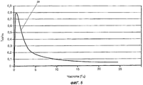
На фиг.5 приведена типичная кривая короткого замыкания для электродвигателя с постоянными магнитами в пропульсивной установке согласно настоящему изобретению.Figure 5 shows a typical short circuit curve for a permanent magnet motor in a propulsion system according to the present invention.
Фиг.6 иллюстрирует альтернативную систему для уменьшения скорости и/или ограничения подвижности привода согласно настоящему изобретению.6 illustrates an alternative system for reducing speed and / or limiting the mobility of a drive according to the present invention.
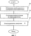
Фиг.7 иллюстрирует способ уменьшения скорости и/или ограничения подвижности привода пропульсивной установки согласно настоящему изобретению.7 illustrates a method of reducing speed and / or limiting the mobility of a drive of a propulsion apparatus according to the present invention.
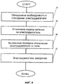
Фиг.8 иллюстрирует альтернативный вариант способа уменьшения скорости и/или ограничения подвижности привода пропульсивной установки согласно настоящему изобретению.FIG. 8 illustrates an alternative embodiment of a method for reducing speed and / or limiting mobility of a drive of a propulsion apparatus according to the present invention.
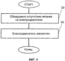
Фиг.9 иллюстрирует еще один альтернативный вариант способа уменьшения скорости и/или ограничения подвижности привода пропульсивной установки согласно настоящему изобретению.FIG. 9 illustrates another alternative embodiment of a method for reducing speed and / or limiting the mobility of a drive of a propulsion apparatus according to the present invention.
Фиг.1-3 были уже описаны ранее. Техническое решение в соответствии с настоящим изобретением будет рассмотрено далее со ссылками на фиг.4-9, которые иллюстрируют различные варианты реализации настоящего изобретения.1-3 are already described previously. The technical solution in accordance with the present invention will be discussed below with reference to figures 4-9, which illustrate various embodiments of the present invention.
Осуществление изобретенияThe implementation of the invention
На фиг.4 представлена пропульсивная система, обеспечивающая уменьшение скорости и/или ограничение подвижности привода (т.е. стопорение электродвигателя в пропульсивной системе) согласно настоящему изобретению. Данная система содержит нагрузку 22 пропульсивной установки, электродвигатель 23 с постоянными магнитами, например, входящий в состав пропульсивной установки, преобразователь 25 частоты, подключенный к силовой электрической сети 24, и переключающее устройство 26. Нагрузкой 22 может являться как гребной винт, так и устройство разворота пропульсивной установки. Через 27 обозначена секция управления преобразователя частоты.FIG. 4 shows a propulsion system that reduces the speed and / or limits mobility of the drive (i.e., locks the motor in the propulsion system) according to the present invention. This system contains a load 22 of the propulsion system, a permanent magnet motor 23, for example, a component of the propulsion system, a
В соответствии с настоящим изобретением переключающее устройство 26, входящее в состав системы для уменьшения скорости и/или ограничения подвижности привода (в частности, для стопорения электродвигателя пропульсивной установки), содержит средства отключения электродвигателя 23 от силовой электрической сети, а также средства закорачивания статорных обмоток электродвигателя 23 с постоянными магнитами. В случае выявления необходимости осуществить стопорение электродвигателя 23 его сначала отключают от силовой электрической сети. Затем производят закорачивание статорных обмоток электродвигателя. Это закорачивание может быть выполнено таким образом, что статорные обмотки электродвигателя 23 одновременно подключаются к контуру заземления оборудования (не изображен).In accordance with the present invention, the switching device 26, which is part of the system to reduce the speed and / or limit the mobility of the drive (in particular, to lock the electric motor of the propulsion system), comprises means for disconnecting the electric motor 23 from the power mains, as well as means for shorting the stator windings of the electric motor 23 with permanent magnets. If it is necessary to lock the electric motor 23, it is first disconnected from the power mains. Then, the stator windings of the electric motor are short-circuited. This shorting can be performed in such a way that the stator windings of the electric motor 23 are simultaneously connected to the equipment ground loop (not shown).
Управление переключающим устройством 26 может осуществляться, например, от секции 27 управления преобразователя частоты. В качестве электродвигателя 23 с постоянными магнитами может быть применен, в частности, синхронный электродвигатель, входящий в состав пропульсивной установки. Двигательные модули 10, 11 устройства разворота могут, например, также содержать электродвигатели 23 с постоянными магнитами. При этом способ стопорения электродвигателя согласно настоящему изобретению может быть использован для переключения более чем одного электродвигателя.The switching device 26 can be controlled, for example, from the control section 27 of the frequency converter. As the permanent magnet electric motor 23, in particular, a synchronous electric motor, which is part of the propulsion system, can be used. The
На фиг.5 представлена типичная кривая (обозначенная, как 28) короткого замыкания для электродвигателя с постоянными магнитами в пропульсивной системе согласно настоящему изобретению. При закорачивании статорных обмоток электродвигателя с постоянными магнитами момент короткого замыкания оказывается столь значительным, что этого момента более чем достаточно для противодействия моментам, индуцируемым движением судна и морскими течениями. Таким образом, состояние системы всегда соответствует точке слева от пикового значения на графике момента. При этом скорость вращения гребного винта будет составлять менее 10% его номинальной скорости и в типичном случае равняться 2-5% этой номинальной скорости.Figure 5 presents a typical curve (designated as 28) short circuit for a permanent magnet motor in a propulsive system according to the present invention. When shorting the stator windings of an electric motor with permanent magnets, the short circuit time is so significant that this moment is more than enough to counteract the moments induced by the movement of the vessel and sea currents. Thus, the state of the system always corresponds to the point to the left of the peak value in the moment graph. In this case, the rotational speed of the propeller will be less than 10% of its nominal speed and, in a typical case, will be 2-5% of this nominal speed.
На фиг.6 представлена альтернативная пропульсивная система согласно настоящему изобретению. Данная альтернативная система содержит гребной винт 29 и электродвигатель 23 с постоянными магнитами, входящими в состав пропульсивной установки. Система по изобретению содержит также преобразователь 32 частоты, подключенный к силовой электрической сети 31, и переключающее устройство 33. Через 34 обозначена секция управления преобразователя частоты.6 shows an alternative propulsion system according to the present invention. This alternative system comprises a
В соответствии с данным вариантом изобретения переключающее устройство 33, входящее в состав системы для уменьшения скорости и/или ограничения подвижности привода (системы стопорения привода), содержит средства отключения электродвигателя 23 от силовой электрической сети, а также средства закорачивания статорных обмоток электродвигателя 23 с постоянными магнитами. В случае выявления необходимости осуществить стопорение электродвигателя 23 его сначала отключают от силовой электрической сети. Затем производится закорачивание статорных обмоток электродвигателя 23 с постоянными магнитами через преобразователь 32 частоты.In accordance with this embodiment of the invention, the switching
Короткое замыкание через преобразователь частоты может быть осуществлено с применением полупроводников. В качестве электродвигателя 23 с постоянными магнитами может быть применен, в частности, синхронный электродвигатель, входящий в состав пропульсивной установки. При этом закорачивание может быть выполнено таким образом, что статорные обмотки электродвигателя 23 одновременно подключаются к контуру заземления оборудования.A short circuit through the frequency converter can be carried out using semiconductors. As the permanent magnet electric motor 23, in particular, a synchronous electric motor, which is part of the propulsion system, can be used. In this case, shorting can be performed in such a way that the stator windings of the electric motor 23 are simultaneously connected to the equipment ground loop.
Управление переключающим устройством 33 может осуществляться, например, от секции 34 управления преобразователя частоты. Двигательные модули 10, 11 устройства разворота могут, например, также содержать электродвигатели 23 с постоянными магнитами. При этом система стопорения электродвигателя пропульсивной системы согласно настоящему изобретению может быть использована для переключения электродвигателя более чем в одной пропульсивной установке.The switching
Фиг.7 иллюстрирует способ уменьшения скорости и/или ограничения подвижности привода (т.е. способ стопорения электродвигателя пропульсивной системы) согласно настоящему изобретению. Как уже упоминалось, пропульсивная система содержит гребной винт и гребной электродвигатель с постоянными магнитами, входящие в состав пропульсивной установки, а также преобразователь частоты, подключенный к силовой электрической сети, и переключающее устройство. В соответствии со способом по настоящему изобретению сначала, на шаге 35, устанавливают необходимость в стопорении электродвигателя. Когда такая необходимость установлена, на шаге 36 гребной электродвигатель отключают от силовой электрической сети. Затем на шаге 37 производят закорачивание статорных обмоток гребного электродвигателя. Способ стопорения гребного электродвигателя пропульсивной установки согласно изобретению может быть также реализован применительно к стопорению более чем одного электродвигателя.7 illustrates a method for reducing speed and / or limiting the mobility of a drive (i.e., a method for locking a motor of a propulsion system) according to the present invention. As already mentioned, the propulsive system contains a propeller and a propeller with permanent magnets, which are part of the propulsive installation, as well as a frequency converter connected to the power mains and a switching device. In accordance with the method of the present invention, first, at
Фиг.8 иллюстрирует альтернативный вариант способа уменьшения скорости и/или ограничения подвижности привода (способа стопорения гребного электродвигателя) в пропульсивной системе согласно настоящему изобретению. Пропульсивная система содержит гребной винт и гребной электродвигатель с постоянными магнитами, входящие в состав пропульсивной установки, а также преобразователь частоты, подключенный к силовой электрической сети, и переключающее устройство. В соответствии со способом по настоящему изобретению сначала, на шаге 35, устанавливается необходимость в стопорении гребного электродвигателя. Когда такая необходимость установлена, на шаге 36 гребной электродвигатель отключают от силовой электрической сети. После того, как гребной электродвигатель был отключен от силовой электрической сети, на шаге 38 осуществляют проверку того, что он действительно отключен. Затем на шаге 37 производят закорачивание статорных обмоток гребного электродвигателя. Способ стопорения гребного электродвигателя пропульсивной установки согласно изобретению может быть также реализован применительно к стопорению более чем одной пропульсивной установки.FIG. 8 illustrates an alternative embodiment of a method for reducing speed and / or limiting drive mobility (a method of locking a propeller motor) in a propulsion system according to the present invention. The propulsive system contains a propeller and a propeller with permanent magnets, which are part of the propulsion system, as well as a frequency converter connected to the power mains and a switching device. In accordance with the method of the present invention, first, in
Фиг.9 иллюстрирует еще один альтернативный вариант способа уменьшения скорости и/или ограничения подвижности привода в пропульсивной системе согласно настоящему изобретению. Пропульсивная система содержит гребной винт и электродвигатель с постоянными магнитами, входящие в состав пропульсивной установки, преобразователь частоты, подключенный к силовой электрической сети, и переключающее устройство. Двигательные модули 10, 11 устройства разворота, также входящего в состав пропульсивной системы, могут, например, также содержать электродвигатели с постоянными магнитами. В соответствии со способом по настоящему изобретению сначала, на шаге 39, обнаруживается отсутствие питания, которое должно подаваться на электродвигатель. Когда такое отсутствие питания обнаружено, на шаге 40 производят закорачивание статорных обмоток электродвигателя. Данный вариант способа стопорения электродвигателя в пропульсивной системе согласно изобретению также может быть реализован применительно к стопорению более чем одного электродвигателя.FIG. 9 illustrates another alternative embodiment of a method for reducing speed and / or limiting drive mobility in a propulsion system according to the present invention. The propulsive system contains a propeller and a permanent magnet electric motor, which are part of the propulsion system, a frequency converter connected to the power mains, and a switching device. The
Таким образом, в соответствии с настоящим изобретением созданы пропульсивная система и способ, соответствующие новому решению задачи стопорения электродвигателя судовой пропульсивной системы. Данное решение позволяет избежать некоторых недостатков, присущих уровню техники, и одновременно реализовать преимущество, состоящее в более простой конструкции и повышенной экономичности, а также в большей простоте использования и улучшенной эксплуатационной надежности.Thus, in accordance with the present invention, a propulsion system and method are created corresponding to a new solution to the problem of locking the electric motor of a ship propulsion system. This solution avoids some of the disadvantages inherent in the prior art, and at the same time realize the advantage of a simpler design and increased efficiency, as well as greater ease of use and improved operational reliability.
Следует отметить, что приведенные примеры осуществления настоящего изобретения не определяют границы изобретения, которое охватывает все модификации, эквиваленты и альтернативные варианты, соответствующие идее и объему изобретения, определяемым прилагаемой формулой изобретения.It should be noted that the above embodiments of the present invention do not define the scope of the invention, which covers all modifications, equivalents and alternative options that are consistent with the idea and scope of the invention defined by the attached claims.
Claims (22)
Applications Claiming Priority (2)
| Application Number | Priority Date | Filing Date | Title |
|---|---|---|---|
| FI20020619A FI115393B (en) | 2002-03-28 | 2002-03-28 | System and method for braking the propulsion unit motor |
| FI20020619 | 2002-03-28 |
Publications (2)
| Publication Number | Publication Date |
|---|---|
| RU2004130854A RU2004130854A (en) | 2005-08-27 |
| RU2301173C2 true RU2301173C2 (en) | 2007-06-20 |
Family
ID=8563673
Family Applications (1)
| Application Number | Title | Priority Date | Filing Date |
|---|---|---|---|
| RU2004130854/09A RU2301173C2 (en) | 2002-03-28 | 2003-03-28 | System and method of stopping the electric motor of propulsion plant |
Country Status (15)
| Country | Link |
|---|---|
| US (1) | US7218070B2 (en) |
| EP (1) | EP1488503B1 (en) |
| JP (1) | JP2005522170A (en) |
| KR (1) | KR100968517B1 (en) |
| CN (1) | CN1643772A (en) |
| AT (1) | ATE441242T1 (en) |
| AU (1) | AU2003216754B2 (en) |
| CA (1) | CA2480255C (en) |
| DE (1) | DE60328976D1 (en) |
| DK (1) | DK1488503T3 (en) |
| ES (1) | ES2328030T3 (en) |
| FI (1) | FI115393B (en) |
| NO (1) | NO331291B1 (en) |
| RU (1) | RU2301173C2 (en) |
| WO (1) | WO2003084045A1 (en) |
Families Citing this family (16)
| Publication number | Priority date | Publication date | Assignee | Title |
|---|---|---|---|---|
| TWI281773B (en) * | 2004-02-25 | 2007-05-21 | Delta Electronics Inc | A real-time stopping fan method and structure thereof |
| ATE412788T1 (en) * | 2004-04-06 | 2008-11-15 | Lg Electronics Inc | METAL PRODUCT COVERED WITH AN ULTRAHYDROPHILE AND ANTIBACTERIAL THIN FILM AND PROCESS FOR PRODUCTION THEREOF |
| JP2006115558A (en) * | 2004-10-12 | 2006-04-27 | Kayaba Ind Co Ltd | Buffer |
| FR2891960B1 (en) * | 2005-10-12 | 2008-07-04 | Leroy Somer Moteurs | ELECTROMECHANICAL DRIVE SYSTEM, IN PARTICULAR FOR PROGRESSIVE CAVITY PUMP FOR OIL WELL. |
| DE102006003254A1 (en) * | 2006-01-24 | 2007-07-26 | Robert Bosch Gmbh | Operating method for electrical machine with pulse-controlled inverter in case of disturbance, involves switching electrical machine into de-energizing mode and into short-circuit mode |
| US7841290B1 (en) | 2006-02-14 | 2010-11-30 | The United States Of America As Represented By The Secretary Of The Navy | Marine shaftless external propulsor |
| FI119136B (en) * | 2006-06-06 | 2008-07-31 | Abb Oy | Power Consumption System |
| US7786608B2 (en) * | 2008-11-17 | 2010-08-31 | General Electric Company | Protection system for wind turbine |
| DE102009017157B4 (en) * | 2009-04-15 | 2011-02-17 | Siemens Aktiengesellschaft | Method for supplying an electrical ship's electrical system with external energy, ship with such a foreign energy supply and retrofit method for this |
| US20120079842A1 (en) * | 2010-10-01 | 2012-04-05 | Min-Ho Lee | Refrigerator having circulation fan controller for saving power consumption |
| CN102001433A (en) * | 2010-11-30 | 2011-04-06 | 惠生(南通)重工有限公司 | Propulsion unit of self-propelling crane ship |
| CN102211656A (en) * | 2011-05-11 | 2011-10-12 | 上海海事大学 | Propulsion drive structure for ship electric propulsion system |
| FR2987705B1 (en) * | 2012-03-02 | 2016-11-25 | Alstom Transport Sa | SYNCHRONOUS ELECTRIC MACHINE SUPPLY CHAIN, ELECTRICAL TRACTION SYSTEM COMPRISING SUCH A CHAIN, AND METHOD FOR CONTROLLING SUCH A CHAIN |
| CA2954717A1 (en) * | 2016-03-24 | 2017-09-24 | Rolls-Royce North American Technologies, Inc. | Windmill synchronization in an electric propulsion system |
| CN106542075B (en) * | 2016-10-17 | 2018-05-01 | 武汉船用电力推进装置研究所(中国船舶重工集团公司第七一二研究所) | A kind of Electrical Propulsion Ship brake control method |
| KR102479984B1 (en) | 2020-10-15 | 2022-12-21 | 김주형 | Medical diagnosis apparatus capable of operating multi-mode |
Family Cites Families (34)
| Publication number | Priority date | Publication date | Assignee | Title |
|---|---|---|---|---|
| US1332631A (en) * | 1916-02-05 | 1920-03-02 | Robert V Morse | Submarine-propulsion system |
| US1555244A (en) * | 1917-02-03 | 1925-09-29 | Westinghouse Electric & Mfg Co | Motor-control system |
| US1481882A (en) * | 1920-02-16 | 1924-01-29 | Gen Electric | Electric ship propulsion |
| US1481853A (en) * | 1920-02-16 | 1924-01-29 | Gen Electric | Electric ship propulsion |
| US1411987A (en) * | 1921-01-29 | 1922-04-04 | Gen Electric | Ship-propulsion system |
| US2084177A (en) * | 1936-02-29 | 1937-06-15 | Gen Electric | Electric power system |
| US2451936A (en) * | 1946-11-21 | 1948-10-19 | Westinghouse Electric Corp | Propulsion drive |
| US2447643A (en) * | 1947-01-23 | 1948-08-24 | Westinghouse Electric Corp | Ship propulsion control |
| US3812411A (en) * | 1973-02-20 | 1974-05-21 | Us Navy | Dynamic braking of a gas turbine powered ship propulsion system utilizing a d.c.electric drive |
| US3997824A (en) * | 1973-04-20 | 1976-12-14 | General Electric Company | Electrical propulsion system and control arrangements therefor |
| JPS553763B2 (en) * | 1973-07-11 | 1980-01-26 | ||
| US3993912A (en) * | 1974-06-10 | 1976-11-23 | General Electric Company | Marine propulsion system |
| US4024443A (en) * | 1975-09-09 | 1977-05-17 | The United States Of America As Represented By The Secretary Of The Navy | A.C.-powered, commutated electric motor |
| DE2620346A1 (en) * | 1976-05-07 | 1977-11-17 | Linde Ag | Rapid braking of async. squirrel cage motors - is achieved by short circuiting of stator windings and by switching loading resistors into one or more phases (NL 9.11.77) |
| US4316722A (en) * | 1980-01-09 | 1982-02-23 | Twin Disc, Incorporated | Propulsion system for submarine |
| SU901099A1 (en) * | 1980-06-25 | 1982-01-30 | Московский Ордена Ленина И Ордена Трудового Красного Знамени Институт Инженеров Железнодорожного Транспорта | Apparatus for braking vehicle |
| US4338525A (en) | 1981-01-05 | 1982-07-06 | Westinghouse Electric Corp. | Marine propulsion system |
| US4388525A (en) * | 1981-02-11 | 1983-06-14 | Fairchild Camera & Instrument Corp. | Precision optical spacers for image sensor filters |
| JPS57197397A (en) * | 1981-05-29 | 1982-12-03 | Taiho Kensetsu Kk | Shield drilling machine |
| JPH0728553B2 (en) | 1982-03-31 | 1995-03-29 | 株式会社日立製作所 | Motor drive circuit |
| JPS61196777A (en) * | 1985-02-22 | 1986-08-30 | Alps Electric Co Ltd | Drive circuit of polyphase direct drive motor |
| JPS6220738A (en) * | 1985-07-20 | 1987-01-29 | Mazda Motor Corp | Motor seat for vehicle |
| JPH0454882A (en) * | 1990-06-22 | 1992-02-21 | Sankyo Seiki Mfg Co Ltd | Stop control circuit of motor |
| JPH05184174A (en) * | 1991-04-04 | 1993-07-23 | Taiheiyo Boeki Kk | Motor controlling circuit |
| US5199912A (en) * | 1991-08-15 | 1993-04-06 | Newport News Shipbuilding And Dry Dock Company | Electric power system for marine vehicles |
| JPH05219767A (en) * | 1992-02-04 | 1993-08-27 | Hitachi Ltd | Power transmission system for engine |
| JPH08275572A (en) * | 1995-04-03 | 1996-10-18 | Shibaura Eng Works Co Ltd | Motor controller and massage machine employing it |
| EP0742498A3 (en) | 1995-05-11 | 1998-01-14 | Siemens Aktiengesellschaft | Implementation of a single channel code program in a system with a two-channel safety-oriented structure |
| JPH0947054A (en) * | 1995-07-28 | 1997-02-14 | Fanuc Ltd | Dynamic brake circuit for servo motor |
| US5684690A (en) * | 1996-08-16 | 1997-11-04 | The United States Of America As Represented By The Secretary Of The Navy | Integrated electrical power supply system for propulsion and service control |
| JPH10234105A (en) * | 1997-02-19 | 1998-09-02 | Aisin Aw Co Ltd | Start controller for motor vehicle derive equipment |
| US6188139B1 (en) * | 1999-01-20 | 2001-02-13 | Electric Boat Corporation | Integrated marine power distribution arrangement |
| FI108119B (en) * | 1999-01-26 | 2001-11-30 | Abb Azipod Oy | Turning a propulsion unit |
| CA2377511A1 (en) * | 1999-06-24 | 2001-01-04 | Siemens Aktiengesellschaft | Drive and propulsion system for ships |
-
2002
- 2002-03-28 FI FI20020619A patent/FI115393B/en not_active IP Right Cessation
-
2003
- 2003-03-28 EP EP03712178A patent/EP1488503B1/en not_active Expired - Lifetime
- 2003-03-28 DK DK03712178T patent/DK1488503T3/en active
- 2003-03-28 WO PCT/FI2003/000244 patent/WO2003084045A1/en active Application Filing
- 2003-03-28 KR KR1020047015283A patent/KR100968517B1/en not_active IP Right Cessation
- 2003-03-28 CN CNA038073730A patent/CN1643772A/en active Pending
- 2003-03-28 CA CA2480255A patent/CA2480255C/en not_active Expired - Fee Related
- 2003-03-28 DE DE60328976T patent/DE60328976D1/en not_active Expired - Lifetime
- 2003-03-28 AU AU2003216754A patent/AU2003216754B2/en not_active Ceased
- 2003-03-28 RU RU2004130854/09A patent/RU2301173C2/en not_active IP Right Cessation
- 2003-03-28 ES ES03712178T patent/ES2328030T3/en not_active Expired - Lifetime
- 2003-03-28 AT AT03712178T patent/ATE441242T1/en not_active IP Right Cessation
- 2003-03-28 US US10/507,379 patent/US7218070B2/en not_active Expired - Fee Related
- 2003-03-28 JP JP2003581337A patent/JP2005522170A/en active Pending
-
2004
- 2004-10-28 NO NO20044660A patent/NO331291B1/en not_active IP Right Cessation
Also Published As
| Publication number | Publication date |
|---|---|
| KR100968517B1 (en) | 2010-07-08 |
| RU2004130854A (en) | 2005-08-27 |
| JP2005522170A (en) | 2005-07-21 |
| CN1643772A (en) | 2005-07-20 |
| FI20020619A (en) | 2003-09-29 |
| KR20040098028A (en) | 2004-11-18 |
| EP1488503A1 (en) | 2004-12-22 |
| NO331291B1 (en) | 2011-11-21 |
| FI115393B (en) | 2005-04-29 |
| US7218070B2 (en) | 2007-05-15 |
| FI20020619A0 (en) | 2002-03-28 |
| EP1488503B1 (en) | 2009-08-26 |
| US20050170716A1 (en) | 2005-08-04 |
| NO20044660L (en) | 2004-10-28 |
| CA2480255C (en) | 2012-01-10 |
| AU2003216754A1 (en) | 2003-10-13 |
| ES2328030T3 (en) | 2009-11-06 |
| AU2003216754B2 (en) | 2007-09-20 |
| WO2003084045A1 (en) | 2003-10-09 |
| DE60328976D1 (en) | 2009-10-08 |
| ATE441242T1 (en) | 2009-09-15 |
| DK1488503T3 (en) | 2009-11-02 |
| CA2480255A1 (en) | 2003-10-09 |
Similar Documents
| Publication | Publication Date | Title |
|---|---|---|
| RU2301173C2 (en) | System and method of stopping the electric motor of propulsion plant | |
| DK1960260T3 (en) | The hybrid drive system for a watercraft | |
| EP2483146B1 (en) | Electric drive shaft and vehicle comprising such an electric drive shaft | |
| US5684690A (en) | Integrated electrical power supply system for propulsion and service control | |
| EP2627557B1 (en) | Marine propulsion systems | |
| EP1663775B1 (en) | Propulsion system for ships | |
| CA2927524C (en) | Power distribution systems | |
| KR101493623B1 (en) | Variable-pitch propeller | |
| US20120302112A1 (en) | Ship drive system having a plurality of electric drive shafts | |
| JP2014505621A (en) | Propulsion system | |
| JPH08207893A (en) | Electric propulsion device for ship | |
| Radan | Power electronic converters for ship propulsion electric motors | |
| JPS59190084A (en) | Inboard distribution network connecting feed device | |
| JPH05219767A (en) | Power transmission system for engine | |
| JP6298967B2 (en) | Frequency converter for electric propulsion ship and electric propulsion ship | |
| JPH033474B2 (en) | ||
| CN214084714U (en) | Hull electric propulsion device | |
| WO2001026962A1 (en) | Electrical propulsion system | |
| JP2024011134A (en) | Electric power system for ship, ship, and method for use of electric power system for ship | |
| JP2014103832A (en) | Inboard load Drive system | |
| Dechambenoit | The Mermaid™ pod propulsion | |
| JPH09140195A (en) | Generator driven through main engine shaft |
Legal Events
| Date | Code | Title | Description |
|---|---|---|---|
| MM4A | The patent is invalid due to non-payment of fees |
Effective date: 20160329 |