RU2299373C2 - Hose valve - Google Patents
Hose valve Download PDFInfo
- Publication number
- RU2299373C2 RU2299373C2 RU2005114568/06A RU2005114568A RU2299373C2 RU 2299373 C2 RU2299373 C2 RU 2299373C2 RU 2005114568/06 A RU2005114568/06 A RU 2005114568/06A RU 2005114568 A RU2005114568 A RU 2005114568A RU 2299373 C2 RU2299373 C2 RU 2299373C2
- Authority
- RU
- Russia
- Prior art keywords
- hose
- valve
- pinch
- passage
- housing
- Prior art date
Links
- 230000000694 effects Effects 0.000 abstract description 2
- 230000002035 prolonged effect Effects 0.000 abstract 1
- 239000000126 substance Substances 0.000 abstract 1
- 239000012530 fluid Substances 0.000 description 10
- 239000007788 liquid Substances 0.000 description 5
- 239000002184 metal Substances 0.000 description 4
- 230000002269 spontaneous effect Effects 0.000 description 4
- 238000004364 calculation method Methods 0.000 description 3
- 238000000034 method Methods 0.000 description 3
- 230000002028 premature Effects 0.000 description 3
- 206010011878 Deafness Diseases 0.000 description 2
- 230000000903 blocking effect Effects 0.000 description 2
- 238000009434 installation Methods 0.000 description 2
- 238000004519 manufacturing process Methods 0.000 description 2
- 230000008569 process Effects 0.000 description 2
- 238000007789 sealing Methods 0.000 description 2
- 208000031968 Cadaver Diseases 0.000 description 1
- 230000009471 action Effects 0.000 description 1
- 230000008859 change Effects 0.000 description 1
- 238000010276 construction Methods 0.000 description 1
- 239000013013 elastic material Substances 0.000 description 1
- 238000005516 engineering process Methods 0.000 description 1
- 238000012423 maintenance Methods 0.000 description 1
- 238000011089 mechanical engineering Methods 0.000 description 1
- 230000007246 mechanism Effects 0.000 description 1
- 210000000056 organ Anatomy 0.000 description 1
- 230000001105 regulatory effect Effects 0.000 description 1
- 230000001052 transient effect Effects 0.000 description 1
- 230000007704 transition Effects 0.000 description 1
- XLYOFNOQVPJJNP-UHFFFAOYSA-N water Substances O XLYOFNOQVPJJNP-UHFFFAOYSA-N 0.000 description 1
- 230000037303 wrinkles Effects 0.000 description 1
Images
Landscapes
- Pipe Accessories (AREA)
Abstract
Description
Изобретение относится к трубопроводной арматуре и может быть использовано для регулирования расхода и давления, а также перекрытия трубопроводов различного назначения, по которым транспортируется жидкая среда или газ.The invention relates to pipe fittings and can be used to control flow and pressure, as well as overlapping pipelines for various purposes, through which a liquid medium or gas is transported.
Известны шланговые или пережимные клапаны, принцип действия которых основан на том, что для перекрытия проходного сечения пережимается труба из эластичного материала (резины), расположенная в корпусе вентиля. Наличие шланга существенно облегчает герметизацию клапана. Как правило, такие устройства снабжены механическими ручными, электромеханическими, гидромеханическими или пневмомеханическими системами для перекрытия (пережатия) шланга [Конструирование и расчет трубопроводной арматуры, Гуревич Д.Ф. Изд-во «Машиностроение», 1968, стр.127].Hose or pinch valves are known, the principle of operation of which is based on the fact that a pipe of elastic material (rubber) located in the valve body is pinched to overlap the bore. The presence of a hose greatly facilitates the sealing of the valve. As a rule, such devices are equipped with mechanical manual, electromechanical, hydromechanical or pneumomechanical systems for closing (clamping) the hose [Design and calculation of pipe fittings, Gurevich DF Publishing House "Engineering", 1968, p.127].
Основные недостатки таких клапанов - это сложность привода пережимного устройства и относительная дороговизна. Наиболее слабым звеном таких механизмов является шланг, воздействие жесткого металлического пережимного устройства, на который существенно сокращает срок службы шланга.The main disadvantages of such valves are the complexity of the drive pinch device and the relative high cost. The weakest link of such mechanisms is the hose, the impact of a rigid metal pinch device, which significantly reduces the life of the hose.
Также известна конструкция запорного клапана, работающего путем пережима резинового вкладыша управляющей средой (вода или воздух), давлением в 10-12 кг/см2, действующей на наружную поверхность резинового вкладыша [Конструирование и расчет трубопроводной арматуры, Гуревич Д.Ф. Изд-во «Машиностроение», 1968, рис.111, стр.132].Also known is the design of a shut-off valve, operating by pinching the rubber liner with a control medium (water or air), with a pressure of 10-12 kg / cm 2 acting on the outer surface of the rubber liner [Design and calculation of pipe fittings, Gurevich D.F. Publishing House "Engineering", 1968, Fig. 1111, p. 132].
Недостатком является сложность конструкции и необходимость в дополнительном источнике сжатого воздуха или жидкости.The disadvantage is the design complexity and the need for an additional source of compressed air or liquid.
Известна конструкция шлангового клапана D=200-300 мм для давления Рр=6 кг/см2 с ручным управлением вкладыша [Конструирование и расчет трубопроводной арматуры, Гуревич Д.Ф. Изд-во «Машиностроение», 1968, рис.104, стр.129]. При вращении маховика две траверсы, расположенные с противоположных сторон шланга, двигаясь навстречу друг другу, пережимают шланг и таким образом разъединяют части трубопровода, прекращая подачу среды.The known design of the hose valve D = 200-300 mm for pressure P p = 6 kg / cm 2 with manual control of the liner [Design and calculation of pipe fittings, Gurevich DF Publishing House "Engineering", 1968, Fig. 104, p. 129]. When the flywheel rotates, two traverses located on opposite sides of the hose, moving towards each other, pinch the hose and thus disconnect the parts of the pipeline, stopping the flow of medium.
Основным недостатком клапана является наличие ручного механического привода и воздействие жесткого металлического пережимного устройства на шланг, который существенно сокращает срок службы шланга.The main disadvantage of the valve is the presence of a manual mechanical actuator and the impact of a rigid metal pinch device on the hose, which significantly reduces the life of the hose.
Наиболее близким к изобретению по первому варианту является запорное устройство по SU 429214 А, кл. F16K 7/07, 31/12, которое по сути является шланговым запорным устройством. Оно было взято в качестве прототипа для первого варианта, как наиболее близкое по технической сущности к заявляемому устройству.Closest to the invention in the first embodiment is a locking device according to SU 429214 A, class.
Конструктивно корпус прототипа представляет два пересекающихся под прямым углом патрубка, оси которых расположены в одной плоскости. Внутри патрубков на их длину вставлены эластичные шланги, при этом один из шлангов с одной стороны заглушен, а с другой снабжен штуцером для подвода управляющей среды.Structurally, the prototype body represents two branch pipes intersecting at right angles, the axes of which are located in the same plane. Elastic hoses are inserted inside the branch pipes along their length, while one of the hoses is plugged on one side and equipped with a fitting for supplying a control medium on the other.
Предложенное в качестве прототипа устройство содержит следующие общие признаки, а именно: корпус выполнен в виде двух пересекающихся цилиндрических патрубков, внутри которых вставлены два эластичных шланга, при этом один из шлангов снабжен штуцером для подвода управляющей среды.The device proposed as a prototype contains the following general features, namely: the body is made in the form of two intersecting cylindrical pipes, inside which two elastic hoses are inserted, while one of the hoses is equipped with a fitting for supplying a control medium.
Основным недостатком прототипа является необходимость источника повышенного давления для обеспечения закрытия устройства, что существенно ограничивает и удорожает его эксплуатацию. Кроме того, при расположении осей патрубков в одной плоскости при пережиме шланга меньшего диаметра большим шлангом имеют место излишне большие деформации пережимаемого шланга, вызывающие образование складок, что, в свою очередь, ведет к нарушению герметичности запирания шланга и преждевременному его выходу из строя.The main disadvantage of the prototype is the need for a source of high pressure to ensure the closure of the device, which significantly limits and increases the cost of its operation. In addition, when the axes of the nozzles are in the same plane when pinching a hose of a smaller diameter with a large hose, excessively large deformations of the pinch hose occur, causing wrinkles, which, in turn, leads to a violation of the tightness of the hose and its premature failure.
Технический результат, на получение которого направлено изобретение, заключается в расширении функциональных возможностей, упрощении конструкции, повышении надежности шлангового клапана и создании рукции, повышении надежности шлангового клапана и создании возможности автономной работы клапана.The technical result to which the invention is directed is to expand the functionality, simplify the design, increase the reliability of the hose valve and create a hand, increase the reliability of the hose valve and create the possibility of autonomous operation of the valve.
Получение технического результата достигается тем, что в шланговом клапане, содержащем корпус с проходным и пережимным шлангами, корпус выполнен с цилиндрическим расширением, а пережимное устройство выполнено в виде глухого пережимного шланга большего диаметра, чем проходной шланг. Пережимной шланг установлен в расширении корпуса параллельно или под углом к проходному шлангу и соединен патрубками с возможностью перекрытия каждого с входом и выходом проходного корпуса. При этом пережимной шланг может быть выполнен большей жесткости, чем проходной шланг, а в патрубке, идущем к выходу устройства, установлен обратный клапан.The technical result is achieved in that in a hose valve comprising a housing with a passage and pinch hoses, the housing is made with cylindrical expansion, and the pinch device is made in the form of a blind pinch hose of a larger diameter than the passage hose. The pinch hose is installed in the extension of the housing parallel or at an angle to the passage hose and is connected by nozzles with the possibility of overlapping each with the entrance and exit of the passage housing. In this case, the pinch hose can be made of greater rigidity than the passage hose, and a non-return valve is installed in the nozzle going to the outlet of the device.
Для второго варианта шлангового клапана наиболее близким по сути является устройство по SU 1626036 А1, Кл. F16K 7/07, 07.02.1991. Устройство относится к шланговым клапанам и содержит корпус с проходным шлангом и пережимное устройство, выполненное в виде двух пережимных шлангов, при этом пережимные шланги установлены друг напротив друга по обе стороны проходного шланга под углом к нему и снабжены штуцерами для подвода управляющего давления.For the second version of the hose valve, the closest in essence is a device according to SU 1626036 A1, Cl.
Предложенное в качестве прототипа устройство содержит следующие общие признаки, а именно: оно содержит корпус с проходным шлангом и пережимное устройство, выполненное в виде двух пережимных шлангов, при этом пережимные шланги установлены друг напротив друга по обе стороны проходного шланга под углом к нему.The device proposed as a prototype contains the following general features, namely: it contains a housing with a passage hose and a pinch device made in the form of two pinch hoses, while the pinch hoses are installed opposite each other on both sides of the passage hose at an angle to it.
Основным недостатком его является необходимость источника дополнительного управляющего давления, т.е. оно работает только от внешнего источника давления (энергии), т.е. требует наличия компрессора или гидростанции со своим приводом, что существенно усложняет конструкцию устройства в целом, а при отсутствии вешнего источника энергии делает невозможным работу такого устройства.Its main disadvantage is the need for a source of additional control pressure, i.e. it works only from an external source of pressure (energy), i.e. It requires a compressor or hydraulic power station with its own drive, which significantly complicates the design of the device as a whole, and in the absence of an external energy source makes it impossible to operate such a device.
Технический результат, на получение которого направлено изобретение, заключается в расширении функциональных возможностей, упрощении конструкции, повышении надежности работы шлангового клапана и создании возможности автономной работы клапана.The technical result to which the invention is directed is to expand the functionality, simplify the design, increase the reliability of the hose valve and create the possibility of autonomous operation of the valve.
Технический результат достигается тем, что в шланговом клапане, содержащем корпус с проходным шлангом и пережимное устройство, корпус выполнен с расширением, а пережимное устройство выполнено в виде двух глухих пережимных шлангов большего диаметра, чем проходной, при этом пережимные шланги установлены напротив друг друга по обе стороны от проходного шланга, параллельно или под углом к нему и соединены с возможностью перекрытия с входом и выходом проходного корпуса, кроме того, пережимные шланги выполнены большей жесткости, чем проходной шланг, а в патрубке, идущем к выходу устройства, установлен обратный клапан.The technical result is achieved in that in a hose valve comprising a housing with a passage hose and a pinch device, the housing is made with expansion, and the pinch device is made in the form of two blind pinch hoses of a larger diameter than the passage, while pinch hoses are installed opposite each other on both the sides of the passage hose, parallel or at an angle to it, and are connected with the possibility of overlapping with the inlet and outlet of the passage housing, in addition, pinch hoses are made more rigid than the passage hose, and in the pipe extending to the output device, a check valve.
Наиболее близким к изобретению по третьему варианту является также запорное устройство по SU 429214 А, кл. F16K 7/07, 31/12, которое по сути является шланговым запорным устройством. Оно было взято в качестве прототипа и для третьего варианта, как наиболее близкое по технической сущности к заявляемому устройству.Closest to the invention in the third embodiment is also a locking device according to SU 429214 A, class.
Конструктивно прототип представляет два пересекающихся под прямым углом патрубка, оси которых расположены в одной плоскости. Внутри патрубков на их длину вставлены эластичные шланги, при этом один из шлангов с одной стороны заглушен, а с другой снабжен штуцером для подвода управляющей среды.Structurally, the prototype represents two branch pipes intersecting at right angles, the axes of which are located in the same plane. Elastic hoses are inserted inside the branch pipes along their length, while one of the hoses is plugged on one side and equipped with a fitting for supplying a control medium on the other.
Предложенное в качестве прототипа устройство содержит следующие общие признаки, а именно: корпус выполнен в виде двух пересекающихся цилиндрических патрубков, внутри которых вставлены два эластичных шланга, при этом один из шлангов снабжен штуцером для подвода повышенного давлении управляющей среды.The device proposed as a prototype contains the following general features, namely: the housing is made in the form of two intersecting cylindrical pipes, inside which two elastic hoses are inserted, one of the hoses being equipped with a fitting for supplying an increased pressure of the control medium.
Основным недостатком прототипа является необходимость источника повышенного давления для обеспечения закрытия устройства, что существенно ограничивает и удорожает его эксплуатацию. Кроме того, при расположении осей патрубков в одной плоскости при пережиме шланга меньшего диаметра большим имеют место излишне большие деформации пережимаемого шланга, вызывающие образование складок, что, в свою очередь, ведет к нарушению герметичности запирания шланга и преждевременному его выходу из строя. Кроме того, при пережиме прямолинейного шланга его стенки растягиваются по длине, создавая дополнительное сопротивление пережиму, и дополнительно деформируются, что также ведет к преждевременному выходу шланга из строя.The main disadvantage of the prototype is the need for a source of high pressure to ensure the closure of the device, which significantly limits and increases the cost of its operation. In addition, when the axes of the nozzles are in the same plane when the hose is clamped with a smaller diameter, large, excessively large deformations of the compressible hose occur, causing wrinkling, which, in turn, leads to a violation of the tightness of the hose and its premature failure. In addition, when pinching a straight hose, its walls stretch along the length, creating additional resistance to pinching, and are additionally deformed, which also leads to premature failure of the hose.
Технический результат, на получение которого направлено изобретение, заключается в расширении функциональных возможностей, упрощении конструкции и повышении надежности работы шлангового клапана.The technical result to which the invention is directed is to expand the functionality, simplify the design and increase the reliability of the hose valve.
Технический результат достигается тем, что в шланговом клапане, содержащем корпус с проходным шлангом и пережимное устройство, согласно изобретению корпус выполнен с расширением, а пережимное устройство выполнено в виде глухого пережимного шланга, установленного параллельно или под углом к проходному шлангу, корпус с проходным шлангом выполнены изогнутыми, пережимной шланг соединен, с возможностью поочередного перекрытия патрубками, с входом и выходом клапана, при этом пережимной шланг выполнен большей жесткости, чем проходной шланг, кроме того, в патрубке, идущем к выходу устройства, установлен обратный клапан.The technical result is achieved by the fact that in a hose valve comprising a housing with a passage hose and a pinch device, according to the invention, the housing is made with expansion, and the pinch device is made in the form of a blind pinch hose mounted parallel or at an angle to the passage hose, the body with the passage hose curved, the pinch hose is connected, with the possibility of alternate overlapping of the nozzles, with the inlet and outlet of the valve, while the pinch hose is made more stiff than the passage hose, in addition, a check valve is installed in the pipe going to the outlet of the device.
Выполнение запорного органа в виде глухого шланга большего диаметра, установленного параллельно или под углом к первому в расширении корпуса и соединенного с входом и выходом клапана патрубками с возможностью перекрытия каждого патрубка, позволяет устанавливать в обоих шлангах одинаковое давление. В этом случае большее сечение глухого шланга обеспечивает большую силу воздействия на проходной шланг. Глухой шланг расправляется и пережимает проходной. Клапан (запорное устройство) перекрывается.The execution of the locking element in the form of a larger diameter blind hose mounted parallel or at an angle to the first in the housing extension and connected to the inlet and outlet of the valve by nozzles with the possibility of overlapping each nozzle, makes it possible to set the same pressure in both hoses. In this case, a larger cross section of the blind hose provides a greater force on the inlet hose. A blank hose straightens and pinches the passage. The valve (shut-off device) is closed.
При установке двух глухих пережимных шлангов большего диаметра по обе стороны от проходного шланга пережим осуществляется с двух сторон.When installing two blank pinch hoses of larger diameter on both sides of the hose inlet, pinch is carried out on both sides.
Двухсторонний пережим облегчает перекрытие трубопроводов большего диаметра.Double-sided pinch makes it easier to block larger pipelines.
Для увеличения надежности перекрытия запорные шланги берутся большей жесткости, чем проходной. Большая жесткость запорного шланга позволяет дополнительно увеличить усилие пережима и, соответственно, увеличить надежность запирания. Помимо сказанного, пережимной более жесткий шланг делает вентиль нормально запертым, т.е. при открытом входном патрубке и закрытом выходном даже при отсутствии давления транспортируемой среды, вентиль будет закрытым. При появлении давления среды в трубопроводной сети усилие запирания увеличивается. Кроме того, с помощью увеличения жесткости пережимного шланга можно устанавливать и регулировать порог срабатывания клапана.To increase the reliability of the shutoff, the locking hoses are taken with greater rigidity than the passage. The high rigidity of the locking hose allows you to further increase the clamping force and, accordingly, increase the locking reliability. In addition, the pinch stiffer hose makes the valve normally closed, i.e. when the inlet pipe is open and the outlet is closed, even if there is no pressure of the transported medium, the valve will be closed. When the pressure of the medium in the pipeline network, the locking force increases. In addition, by increasing the stiffness of the pinch hose, the valve threshold can be set and adjusted.
При выключении запорного устройства выводной патрубок подключают к выходу шлангового клапана, а подводной патрубок перекрывают. В результате этого пережимной патрубок подключается к пустой отводной трубе, и он освобождается от жидкости, отпуская проходной шланг и открывая запорное устройство. При дальнейшем наполнении отводной трубы давление в ней увеличивается, повышая давление и в пережимном шланге. Становится возможен повторный и ненужный пережим проходного шланга. При частичном или полном его перекрытии давление в отводной трубе вновь падает, жидкость из глухого шланга выливается, снова открывая запорное устройство и т.д. Устанавливается неустойчивый пульсирующий переходной режим. Для его исключения в отводном патрубке устанавливают обратный клапан, который не допускает переливания среды из выхода клапана в пережимной шланг и делает невозможным установление переходного режима.When the shut-off device is turned off, the outlet pipe is connected to the outlet of the hose valve, and the underwater pipe is closed. As a result of this, the pinch pipe is connected to an empty outlet pipe, and it is freed from the liquid by releasing the passage hose and opening the locking device. With further filling of the outlet pipe, the pressure in it increases, increasing the pressure in the pinch hose. It becomes possible repeated and unnecessary pinch passage hose. With a partial or complete overlap, the pressure in the outlet pipe drops again, the liquid from the blind hose spills out, again opening the locking device, etc. An unstable pulsating transient mode is established. To exclude it, a non-return valve is installed in the outlet pipe, which does not allow the medium to flow from the valve outlet to the pinch hose and makes it impossible to establish a transition mode.
Работа описанных вариантов клапана может быть эффективна только при использовании растягивающихся эластичных шлангов, поскольку для успешной герметизации концы проходного шланга должны быть жестко закреплены. При высоких давлениях использование растягивающегося шланга по условиям прочности становится проблематичным. Применение более прочных армированных шлангов возможно лишь в конструкциях, не допускающих растяжения шлангов в длину. Это достигается выполнением корпуса проходного шланга изогнутым, что допускает «откидывание» (отжим) шланга с точки наибольшего радиуса без растягивания глухим (пережимным) шлангом. Для растягивающихся шлангов изогнутый корпус обеспечивает снижение нагрузки за счет уменьшения или исключения растягивания шланга при запирании устройства.The operation of the described valve options can be effective only when using stretchable flexible hoses, since for successful sealing the ends of the inlet hose must be rigidly fixed. At high pressures, the use of a stretchable hose under conditions of strength becomes problematic. The use of stronger reinforced hoses is possible only in structures that do not allow stretching of the hoses in length. This is achieved by making the passage hose body curved, which allows the hose to “tilt” (wring) from the point of greatest radius without being stretched with a blank (pinch) hose. For stretchable hoses, the curved body reduces the load by reducing or eliminating the stretching of the hose when locking the device.
Таким образом, предлагаемый клапан работает за счет энергии транспортируемой среды, конструкция клапана существенно упрощается за счет исключения дополнительного источника управляющего давления, расширяются технологические возможности клапана, пережим шланга становится более щадящим «мягким», благодаря чему повышается надежность и долговечность работы проходного шланга, и улучшаются условия эксплуатации в результате механизации процесса работы устройства за счет энергии транспортируемого продукта.Thus, the proposed valve operates due to the energy of the transported medium, the valve design is greatly simplified by eliminating an additional source of control pressure, the valve’s technological capabilities are expanded, the hose clamping becomes more gentle "soft", which increases the reliability and durability of the passage hose, and improves operating conditions as a result of mechanization of the operation of the device due to the energy of the transported product.
Отличием от прототипа является выполнение пережимного устройства в виде глухого шланга большего диаметра, установленного параллельно или под углом к проходному шлангу, в расширении или специальном корпусе, и соединенного патрубками с входом и выходом клапана с возможностью перекрытия. Пережимное устройство может быть выполнено и в виде двух глухих шлангов, установленных напротив друг друга по обе стороны от проходного шланга. При этом для увеличения надежности запирания запорный шланг берется большей жесткости, чем проходной. В патрубке, идущем к выходу запорного устройства, устанавливается обратный клапан. Проходные корпус и шланг выполнены криволинейными. Наличие отличительных признаков позволяет сделать вывод о соответствии заявляемого устройства критерию «новизна».The difference from the prototype is the implementation of the pinch device in the form of a blind hose of a larger diameter, installed parallel or at an angle to the passage hose, in an extension or a special case, and connected by nozzles to the valve inlet and outlet with the possibility of overlapping. The pinch device can also be made in the form of two blind hoses mounted opposite each other on both sides of the passage hose. At the same time, to increase the reliability of locking, the locking hose is taken with greater rigidity than the passage. A check valve is installed in the pipe going to the outlet of the shut-off device. The bushing and hose are made curved. The presence of distinctive features allows us to conclude that the claimed device meets the criterion of "novelty."
В технике широко используют шланги: армированные и неармированные, патрубки, краны и обратные клапана в гидропневмоавтоматике и гидроприводах различного назначения для перемещения с помощью поршней и диафрагм разного рода исполнительных механизмов (Гидравлика, гидромашины и гидроприводы: Учебник для машиностроительных вузов / Т.М.Башта, С.С.Руднев, Б.Б.Некрасов и др. - 2-е изд., перераб. - М.: Машиностроение, 1982, с.356).Hoses are widely used in technology: reinforced and non-reinforced, pipes, taps and check valves in hydropneumatic automation and hydraulic actuators for various purposes to move various actuators using pistons and diaphragms (Hydraulics, hydraulic machines and hydraulic actuators: Textbook for engineering universities / T.M.Bashta , S.S. Rudnev, B. B. Nekrasov et al. - 2nd ed., Revised. - M.: Mechanical Engineering, 1982, p.356).
Известно устройство по SU 1813950 А, кл. F16K 7/07, 07.05.1993, в котором с входом и выходом соединяется запорный орган в виде тора. Он установлен в гнезде, имеющем отверстия в стенках. При запирании устройства тор перекрывает отверстия гнезда. При открытии клапана тор сжимается, открывая отверстия. В этом случае жидкость проходит через стенку с отверстиями и затем через щель между гнездом и тором, которые оказывают потоку жидкости гидравлическое сопротивление, что увеличивает общие потери энергии в системе. В заявляемом шланговом же клапане проходное отверстие шланга перекрывается фактически поджимаемой пережимным шлангом стенкой проходного шланга. При открытии клапана проходной шланг, наоборот, расправляется, не оказывая сопротивление движущемуся потоку жидкости. То есть сходный признак различно влияет на процессы функционирования и качество работы органов устройства.A device is known according to SU 1813950 A, class.
В известном устройстве по US 3018793 А, кл. F16K 7/06, 30.01.1962 в части параллельного расположения шлангов, пережим проходного шланга осуществляется жесткой механической системой, в которой только роль силового органа (привода) выполняет шланг. В этом случае замена пережимного шланга на другой силовой орган (гидроцилиндр, диафрагму) никак не может повлиять на характер пережима. Расположение шланга также не имеет значения, поскольку усилие от него передается непосредственно на металлическую раму, которая и осуществляет пережим проходного шланга. В заявляемом же устройстве оба шланга расположены в одном силовом контуре и воздействуют непосредственно друг на друга. То есть в заявляемом случае исключается жесткое силовое воздействие на пережимаемый шланг.In a known device according to US 3018793 A, cl.
Совокупности признаков заявляемого изобретения, а именно: выполнение пережимного устройства в виде глухого шланга большего диаметра, чем проходной, установленного параллельно или под углом к проходному в корпусе; установка двух глухих шлангов по обе стороны от проходного; соединение глухих шлангов патрубками с входом и выходом клапана с возможностью перекрытия каждого патрубка; подбор запорных шлангов большей жесткости, чем проходного; установка в патрубке, идущем к выходу запорного устройства обратного клапана, и изготовление корпуса с проходным шлангом изогнутыми обеспечивает создание новых свойств клапана (запорного устройства): расширение технологических возможностей, упрощение конструкции и повышение надежности работы за счет ликвидации механических систем привода и создание щадящего (мягкого) пережима проходного шланга, улучшение условий обслуживания путем механизации процесса работы устройства под действием энергии и давления транспортируемого продукта, что свидетельствует о соответствии заявляемого изобретения критерию «изобретательский уровень».The totality of the features of the claimed invention, namely: the implementation of the pinch device in the form of a blind hose of a larger diameter than the passage, installed in parallel or at an angle to the passage in the housing; installation of two blind hoses on both sides of the passage; connection of deaf hoses with nozzles with valve inlet and outlet with the possibility of overlapping each nozzle; selection of locking hoses of greater rigidity than passage; the installation of a non-return valve in the outlet that goes to the outlet of the shut-off device and the manufacture of a body with a bent hose ensures the creation of new properties of the valve (shut-off device): expanding technological capabilities, simplifying the design and increasing reliability by eliminating mechanical drive systems and creating a gentle (soft ) pinch the inlet hose, improve service conditions by mechanizing the process of the device under the action of energy and pressure of the transported product, the evidence of conformity of the present invention, the criterion of "inventive step".
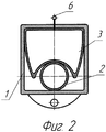
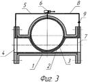
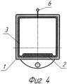
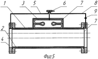
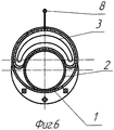
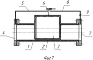
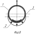
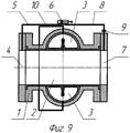
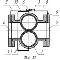
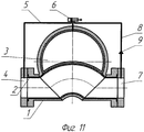
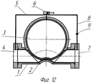
Заявляемое изобретение поясняется чертежами, где на фиг.1 показан вариант заявляемого изобретения, охарактеризованный п.1, 2 и 3 формулы изобретения, в котором пережимной шланг установлен под углом к проходному шлангу и устройство находится в открытом положении; на фиг.2 - его вид сбоку в разрезе; на фиг.3 - этот же вариант при перекрытом рабочем проходе; на фиг.4 - его вид сбоку при перекрытом рабочем проходе в разрезе; на фиг.5 - вариант заявляемого устройства, охарактеризованный п.1, 2 и 3 формулы изобретения, в котором пережимной шланг установлен вдоль оси проходного шланга и устройство находится в открытом положении; на фиг.6 - его вид сбоку; на фиг.7 - вид этого варианта в перекрытом положении; на фиг.8 - его вид сбоку в перекрытом положении в разрезе; на фиг.9 - вариант заявляемого изобретения, охарактеризованный п.4, 5 и 6 в открытом положении; на фиг.10 - вид этого варианта в закрытом состоянии; на фиг.11 - вариант заявляемого устройства, охарактеризованный п.7, 8 и 9 показанный в открытом положении; на фиг.12 - тот же вариант в закрытом состоянии.The invention is illustrated by drawings, in which Fig. 1 shows a variant of the claimed invention, characterized by
Клапан может использоваться и как запорное устройство. Конструктивно он представляет следующее.The valve can also be used as a locking device. Structurally, he presents the following.
В цилиндрическом корпусе 1 (фиг.1, 2, 3, 4) установлен с заделкой по концам на всю длину корпуса проходной шланг 2. Запорный орган в виде глухого пережимного шланга 3 с большим диаметром, чем шланг 1, установлен под углом к оси корпуса 1 в расширении корпуса. Жесткость шланга 3 превышает жесткость шланга 2. Вход 4 шлангового клапана соединен патрубком 5 через трехходовой кран 6 с шлангом 3, а выход 7 шлангового клапана соединен патрубком 8 через кран 6 с тем же пережимным шлангом 3. В патрубке 8 установлен регулируемый обратный клапан 9. Шланговый клапан работает следующим образом.In the cylindrical body 1 (Figs. 1, 2, 3, 4), a
На фиг.1, 2 показан клапан в открытом положении, поэтому рабочая среда может проходить беспрепятственно через клапан. Закрытие клапана производится с помощью крана 6, который подключает глухой шланг 3 к входу клапана 4. Жидкость от входа 4 через патрубок 5 и кран 6 подается в полость шланга 3. При выравнивании давления в полостях шлангов 2 и 3 шланг 3 расправляется и пережимает шланг 2. Рабочий проход клапана перекрыт (фиг.3, 4). На выходе клапана 7 и примыкающем к нему трубопроводе падает давление. Открытие клапана производится краном 6, который полость шланга 3 с помощью патрубка 8 подключает к выходу клапана 7, т.е. к пустой трубе. Жидкость под давлением шланга 2 выливается из шланга 3 в пустой трубопровод, открывая проходное сечение. Для исключения самопроизвольного закрытия проходного сечения при выравнивании давления на входе и выходе шлангового клапана в патрубке 8 установлен обратный клапан 9.Figure 1, 2 shows the valve in the open position, so the working medium can pass unhindered through the valve. The valve is closed using a
На фиг.5, 6, 7 и 8 показан клапан с проходным шлангом 2 и пережимным шлангом 3, установленным вдоль оси клапана в корпусе 1. Конструктивно он напоминает клапан, показанный на фиг.1 и 2. В корпусе 1 установлен с заделкой по концам на всю длину корпуса проходной шланг 2. Запорный орган в виде шланга 3 выполнен глухим и, в отличие от первого, установлен вдоль оси корпуса 1. Жесткость шланга 3 превышает жесткость шланга 2. Вход клапана 4 соединен патрубком 5 через кран 6 с шлангом 3, а выход клапана 7 соединен патрубком 8 через кран 6 с тем же шлангом 3. В патрубке 8 установлен обратный клапан 9. Работа этого устройства не отличается от работы показанного выше клапана и происходит следующим образом.Figures 5, 6, 7, and 8 show a valve with a
На фиг.5, 6 клапан показан в открытом положении, поэтому рабочая среда проходит беспрепятственно через клапан. Закрытие клапана производится краном 6, который подключает глухой шланг 3 к входу клапана 4. Жидкость от входа 4 через патрубок 5 и кран 6 подается в полость шланга 3. При выравнивании давления в полостях шлангов 2 и 3 шланг 3 расправляется и пережимает шланг 2. Рабочий проход клапана перекрыт (фиг.7, 8). На выходе клапана 7 и примыкающем к нему трубопроводе падает давление. Открытие клапана производится краном 6, который полость шланга 3 с помощью патрубка 8 подключает к выходу клапана 7, т.е. к пустой трубе. Жидкость под давлением шланга 2 выливается из шланга 3 в пустой трубопровод, открывая проходное сечение. Для исключения самопроизвольного закрытия проходного сечения при выравнивании давления на входе и выходе шлангового клапана в патрубке 8 установлен обратный клапан 9.In figures 5, 6, the valve is shown in the open position, so the working medium passes unhindered through the valve. The valve is closed by a
На фиг.9 и 10 поясняется конструкция шлангового клапана с двумя пережимными шлангами, расположенными по обе стороны от проходного. На фиг.9 клапан показан в открытом положении, а на фиг.10 в закрытом.Figures 9 and 10 illustrate the construction of a hose valve with two pinch hoses located on both sides of the passage. In Fig.9, the valve is shown in the open position, and in Fig.10 in the closed position.
Конструктивно он напоминает клапан, показанный на фиг.1 и 2. В корпусе 1 установлен с заделкой по концам на всю длину корпуса проходной шланг 2. Запорный орган в виде двух шлангов 3, выполненных глухими и, в отличие от предыдущего клапана, размещенных по обе стороны от проходного шланга корпуса 1. Жесткость шлангов 3 превышает жесткость шланга 2. Вход клапана 4 соединен патрубком 5 через кран 6 с шлангами 3, а выход клапана 7 соединен патрубком 8 через кран 6 с теми же шлангами 3. В патрубке 8 установлен обратный клапан 9. Патрубок 10 соединяет пережимные шланги 3.Structurally, it resembles the valve shown in figures 1 and 2. In the
Шланговый клапан работает следующим образом. На фиг.9 клапан показан в открытом положении. Закрытие клапана производится краном 6, который подключает глухие шланги 3 к входу клапана 4. Жидкость от входа клапана 4 через патрубок 5 и кран 6 подается в полость шлангов 3. При выравнивании давления в полостях шлангов 2 и 3 шланги 3 заполняются и пережимают шланг 2. Рабочий проход клапана перекрыт (фиг.10). На выходе клапана 7 и примыкающем к нему трубопроводе падает давление. Открытие клапана производится краном 6, который полости шлангов 3 с помощью патрубка 8 подключает к выходу клапана 7, т.е. к пустой трубе. Жидкость под давлением шланга 2 выливается из шлангов 3 в пустой трубопровод, открывая проходное сечение. Для исключения самопроизвольного закрытия проходного сечения при выравнивании давления на входе и выходе шлангового клапана в патрубке 8 установлен обратный клапан 9. Патрубок 10 обеспечивает одинаковое давление в шлангах 3.The hose valve operates as follows. 9, the valve is shown in the open position. The valve is closed by a
На фиг.11 и 12 показан клапан с изогнутым корпусом и проходным шлангом в открытом и закрытом состояниях. Перегиб корпуса позволяет перекрывать рабочее сечение клапана без растяжения проходного шланга, поскольку он может опускаться без растяжения от верхней точки перегиба до противоположной стороны шланга, перекрывая проходное сечение. Конструктивно клапан представляет следующее.11 and 12 show a valve with a curved body and a flow hose in open and closed states. The bend of the housing allows you to overlap the working section of the valve without stretching the inlet hose, since it can fall without stretching from the upper inflection point to the opposite side of the hose, blocking the bore. Structurally, the valve represents the following.
В криволинейном корпусе 1 (фиг.11, 12) установлен с заделкой по концам на всю длину корпуса проходной шланг 2. Запорный орган в виде глухого пережимного шланга 3 с большим диаметром, чем шланг 1, установлен под углом к продольной оси корпуса 1 в расширении корпуса. Жесткость шланга 3 превышает жесткость шланга 2. Вход 4 шлангового клапана соединен патрубком 5 через трехходовой кран 6 с шлангом 3, а выход 7 шлангового клапана соединен патрубком 8 через кран 6 с тем же пережимным шлангом 3. В патрубке 8 установлен регулируемый по усилию поджатия обратный клапан 9. Шланговый клапан работает следующим образом.In a curved housing 1 (Fig. 11, 12), a
На фиг.11 показан клапан в открытом положении, поэтому рабочая среда может проходить беспрепятственно через клапан. Закрытие клапана производится с помощью крана 6, который подключает глухой шланг 3 к входу клапана 4. Жидкость от входа 4 через патрубок 5 и кран 6 подается в полость шланга 3. При выравнивании давления в полостях шлангов 2 и 3 шланг 3 расправляется и пережимает шланг 2. Рабочий проход клапана перекрыт (фиг.12). На выходе клапана 7 и примыкающем к нему трубопроводе падает давление. Открытие клапана производится краном 6, который полость шланга 3 с помощью патрубка 8 подключает к выходу клапана 7, т.е. к пустой трубе. Жидкость под давлением шланга 2 выливается из шланга 3 в пустой трубопровод, открывая проходное сечение. Для исключения самопроизвольного закрытия проходного сечения при выравнивании давления на входе и выходе шлангового клапана в патрубке 8 установлен обратный регулируемый клапан 9. Возможность регулировки клапана 9 позволяет изменять перепад давления между входом и выходом шлангового клапана, что, в свою очередь, обеспечивает возможность управления расходом среды, проходящей через шланговый клапан.11 shows the valve in the open position, so the working medium can pass unhindered through the valve. The valve is closed using a
На фиг.1-12 показаны варианты использования предлагаемого шлангового клапана в качестве запорного устройства.Figure 1-12 shows the options for using the proposed hose valve as a locking device.
В зависимости от метода и системы управления показанные шланговые пережимные клапаны могут играть роль запорного или регулирующего органа или выполнять роль отсечных или обратных клапанов, перекрывая проход при образовании чрезмерно большого потока или при перемене его направления.Depending on the method and control system, the shown hose pinch valves can act as a shut-off or regulating body or act as shut-off or non-return valves, blocking the passage when an excessively large flow is formed or when its direction changes.
Таким образом, предлагаемое устройство позволяет использовать энергию и давление транспортируемого продукта для переключения клапана, исключая использование каких-либо механических систем и, соответственно, необходимость изготовления сложных, дорогостоящих деталей, что расширяет технологические возможности, упрощает конструкцию, повышает надежность, уменьшает металлоемкость и габариты, облегчает использование устройства в трубопроводах больших диаметров, облегчает и упрощает его обслуживание и эксплуатацию.Thus, the proposed device allows you to use the energy and pressure of the transported product to switch the valve, eliminating the use of any mechanical systems and, accordingly, the need to manufacture complex, expensive parts, which extends technological capabilities, simplifies the design, increases reliability, reduces metal consumption and dimensions, facilitates the use of the device in large pipelines, facilitates and simplifies its maintenance and operation.
Claims (10)
Priority Applications (1)
| Application Number | Priority Date | Filing Date | Title |
|---|---|---|---|
| RU2005114568/06A RU2299373C2 (en) | 2005-05-13 | 2005-05-13 | Hose valve |
Applications Claiming Priority (1)
| Application Number | Priority Date | Filing Date | Title |
|---|---|---|---|
| RU2005114568/06A RU2299373C2 (en) | 2005-05-13 | 2005-05-13 | Hose valve |
Publications (2)
| Publication Number | Publication Date |
|---|---|
| RU2005114568A RU2005114568A (en) | 2006-11-20 |
| RU2299373C2 true RU2299373C2 (en) | 2007-05-20 |
Family
ID=37501805
Family Applications (1)
| Application Number | Title | Priority Date | Filing Date |
|---|---|---|---|
| RU2005114568/06A RU2299373C2 (en) | 2005-05-13 | 2005-05-13 | Hose valve |
Country Status (1)
| Country | Link |
|---|---|
| RU (1) | RU2299373C2 (en) |
Cited By (3)
| Publication number | Priority date | Publication date | Assignee | Title |
|---|---|---|---|---|
| RU2359161C1 (en) * | 2008-03-05 | 2009-06-20 | Государственное образовательное учреждение высшего профессионального образования "Иркутский государственный технический университет" (ГОУ ИрГТУ) | Pipeline shut-off device (versions) |
| RU2376519C1 (en) * | 2008-12-10 | 2009-12-20 | Государственное образовательное учреждение высшего профессионального образования "Иркутский государственный технический университет" (ГОУ ИрГТУ) | Closure system for pipelines shut-off |
| RU2554662C1 (en) * | 2014-06-26 | 2015-06-27 | федеральное государственное бюджетное образовательное учреждение высшего образования "Иркутский национальный исследовательский технический университет" (ФГБОУ ВО "ИРНИТУ") | Valve for pipelines shutdown |
Citations (5)
| Publication number | Priority date | Publication date | Assignee | Title |
|---|---|---|---|---|
| CH208807A (en) * | 1939-03-11 | 1940-02-29 | Jules Schloer Aktiengesellscha | Automatic regulator responsive to pressure changes. |
| US3018793A (en) * | 1958-08-05 | 1962-01-30 | American Cyanamid Co | Fluid throttling valve |
| US3468342A (en) * | 1964-11-10 | 1969-09-23 | British Telecommunications Res | Fluid control devices |
| SU1626036A1 (en) * | 1986-08-25 | 1991-02-07 | Производственное объединение "Новокраматорский машиностроительный завод" | Valving device |
| SU1642168A1 (en) * | 1989-02-28 | 1991-04-15 | Предприятие П/Я А-1416 | Hose gate |
-
2005
- 2005-05-13 RU RU2005114568/06A patent/RU2299373C2/en not_active IP Right Cessation
Patent Citations (5)
| Publication number | Priority date | Publication date | Assignee | Title |
|---|---|---|---|---|
| CH208807A (en) * | 1939-03-11 | 1940-02-29 | Jules Schloer Aktiengesellscha | Automatic regulator responsive to pressure changes. |
| US3018793A (en) * | 1958-08-05 | 1962-01-30 | American Cyanamid Co | Fluid throttling valve |
| US3468342A (en) * | 1964-11-10 | 1969-09-23 | British Telecommunications Res | Fluid control devices |
| SU1626036A1 (en) * | 1986-08-25 | 1991-02-07 | Производственное объединение "Новокраматорский машиностроительный завод" | Valving device |
| SU1642168A1 (en) * | 1989-02-28 | 1991-04-15 | Предприятие П/Я А-1416 | Hose gate |
Cited By (3)
| Publication number | Priority date | Publication date | Assignee | Title |
|---|---|---|---|---|
| RU2359161C1 (en) * | 2008-03-05 | 2009-06-20 | Государственное образовательное учреждение высшего профессионального образования "Иркутский государственный технический университет" (ГОУ ИрГТУ) | Pipeline shut-off device (versions) |
| RU2376519C1 (en) * | 2008-12-10 | 2009-12-20 | Государственное образовательное учреждение высшего профессионального образования "Иркутский государственный технический университет" (ГОУ ИрГТУ) | Closure system for pipelines shut-off |
| RU2554662C1 (en) * | 2014-06-26 | 2015-06-27 | федеральное государственное бюджетное образовательное учреждение высшего образования "Иркутский национальный исследовательский технический университет" (ФГБОУ ВО "ИРНИТУ") | Valve for pipelines shutdown |
Also Published As
| Publication number | Publication date |
|---|---|
| RU2005114568A (en) | 2006-11-20 |
Similar Documents
| Publication | Publication Date | Title |
|---|---|---|
| US4322054A (en) | Pinch valve | |
| EP3293439A1 (en) | Water piping system with slam mitigation function of check valve, and control method therefor | |
| IL266979B1 (en) | Diaphragm for fluid control valve and fluid control methods | |
| US6923421B2 (en) | Flexible half sleeve style pinch valve | |
| IT201900002455A1 (en) | Hydraulic system for a heating and domestic hot water generation system. | |
| RU2299373C2 (en) | Hose valve | |
| US2972464A (en) | Flexible conduit valve | |
| CN214838566U (en) | Air bag mounting assembly and rubber soft joint with built-in air bag | |
| SE1100393A1 (en) | Methods and apparatus for single-directional wiring | |
| RU2299374C1 (en) | Hose valve | |
| RU2543085C2 (en) | Control valve (versions) | |
| RU2376519C1 (en) | Closure system for pipelines shut-off | |
| RU2309318C1 (en) | Hose valve | |
| RU65164U1 (en) | BLOCKING VALVE VALVE | |
| RU2359161C1 (en) | Pipeline shut-off device (versions) | |
| CN211447224U (en) | An adjustable flexible shut-off device | |
| CN119022156B (en) | A braided hose assembly | |
| CN213062295U (en) | A flexible shut-off device | |
| KR20130026470A (en) | Temporary piping system for the selected range flow from the whole piping system | |
| RU2722767C1 (en) | Hydraulic drive with throttling control | |
| WO2020070738A1 (en) | An apparatus and method for tunable regulation of fluid or gas flow | |
| CN113606376A (en) | Soft pneumatic valve with paper folding structure and control method thereof | |
| SU289638A1 (en) | DEVICE FOR SYNCHRONIZATION OF WORK OF LARGE NUMBER OF HYDRAULIC EXECUTIVE MECHANISMS | |
| CN112762197A (en) | Formula flow adjustable pneumatic valve is blocked in inflation based on high elastic material | |
| EP1564457A1 (en) | Flexible half sleeve style pinch valve |
Legal Events
| Date | Code | Title | Description |
|---|---|---|---|
| MM4A | The patent is invalid due to non-payment of fees |
Effective date: 20160514 |