RU2299309C2 - Cementing device and method for casing pipe with two cementing plugs - Google Patents
Cementing device and method for casing pipe with two cementing plugs Download PDFInfo
- Publication number
- RU2299309C2 RU2299309C2 RU2005106785/03A RU2005106785A RU2299309C2 RU 2299309 C2 RU2299309 C2 RU 2299309C2 RU 2005106785/03 A RU2005106785/03 A RU 2005106785/03A RU 2005106785 A RU2005106785 A RU 2005106785A RU 2299309 C2 RU2299309 C2 RU 2299309C2
- Authority
- RU
- Russia
- Prior art keywords
- cementing
- casing
- hydromechanical
- centralizers
- well
- Prior art date
Links
Images

Landscapes
- Piles And Underground Anchors (AREA)
- Consolidation Of Soil By Introduction Of Solidifying Substances Into Soil (AREA)
Abstract
Description
Изобретение относится к области бурения скважин, а именно цементирования обсадной колонны.The invention relates to the field of well drilling, namely, casing cementing.
Известен способ цементирования обсадной колонны и устройство, включающее обсадную колонну с элементами технологической оснастки: башмак, башмачный патрубок, обратный клапан, стоп-кольцо, сигнальное кольцо, жесткие или пружинные центраторы, турбулизаторы, скребки, цементировочная головка с установленными нижней и верхней цементировочными пробками [1].A known method of cementing a casing string and a device comprising a casing string with elements of technological equipment: a shoe, a shoe pipe, a check valve, a stop ring, a signal ring, rigid or spring centralizers, turbulators, scrapers, a cementing head with installed lower and upper cementing plugs [ one].
После подготовки ствола скважины спускают обсадную колонну с элементами технологической оснастки (башмак, башмачный патрубок, обратный клапан, стоп-кольцо, жесткие или пружинные центраторы, турбулизаторы, скребки). На верхней трубе обсадной колонны монтируют цементировочную головку, с установленными двумя цементировочными пробками, и ствол скважины промывают.After preparing the wellbore, the casing is lowered with elements of technological equipment (shoe, shoe pipe, check valve, stop ring, rigid or spring centralizers, turbulators, scrapers). A cementing head is mounted on the upper casing pipe, with two cementing plugs installed, and the wellbore is washed.
Затем продавливают нижнюю цементировочную пробку цементным раствором. Закачав необходимое количество цементировочного раствора, сбрасывают верхнюю продавочную пробку. Цементный раствор движется между двумя пробками, которые отделяют его от бурового раствора, предохраняя от загрязнения в обсадной колонне.Then push the bottom cement plug with cement mortar. Having pumped the required amount of cement mortar, dump the top cork. The cement slurry moves between the two plugs that separate it from the drilling fluid, protecting it from contamination in the casing.
Вслед за верхней цементировочной пробкой закачивают продавочную жидкость (чаще всего буровой раствор), которой продавливают цементный раствор в затрубное пространство. Продавливание начинается с момента посадки нижней пробки на стоп-кольцо и прорыва диафрагмы в нижней цементировочной пробке, что достигается повышением давления в колонне.Following the upper cement plug, a squeezing fluid is pumped (most often drilling mud), which is used to push the cement mortar into the annulus. Squeezing starts from the moment the lower plug is placed on the stop ring and the diaphragm breaks in the lower cement plug, which is achieved by increasing the pressure in the column.
Подсчитывают количество продавочной жидкости, закачиваемой в обсадную колонну. Когда остается 1-2 м3 продавочной жидкости, интенсивность ее закачки снижают. Процесс ведут до схождения пробок, посадки верхней пробки на нижнюю. Этот момент характеризуется резким повышением давления. Величина начала резкого повышения давления называется давлением "стоп". После чего величину давления повышают свыше величины давления "стоп" с учетом прочностных характеристик обсадной колонны и оставляют ее под давлением на определенное время.Count the amount of squeeze fluid injected into the casing. When 1-2 m 3 of squeezing liquid remains, the intensity of its injection is reduced. The process is carried out until the convergence of traffic jams, landing of the upper tube on the bottom. This moment is characterized by a sharp increase in pressure. The magnitude of the onset of a sharp increase in pressure is called “stop” pressure. After that, the pressure value is increased above the "stop" pressure value taking into account the strength characteristics of the casing string and leave it under pressure for a certain time.
При этом следят за показанием манометра на устье. Если величина давления за это время на устье не изменяется, то колонна считается герметичной.At the same time, the pressure gauge on the mouth is monitored. If the pressure value during this time at the mouth does not change, then the column is considered airtight.
После избыточное давление в обсадной колонне стравливается и обсадная колонна остается в таком состоянии до образования цементного камня. Дополнительно обсадная колонна может быть испытана на герметичность путем снижения уровня жидкости в обсадной колонне.After that, the overpressure in the casing is vented and the casing stays in this state until the cement stone is formed. Additionally, the casing can be leak tested by lowering the level of fluid in the casing.
После образования кольца цементного камня проводят перфорацию обсадной колонны, цементного кольца и породы для создания гидромеханической связи скважины с пластом.After the formation of the cement stone ring, the casing, cement ring and rock are perforated to create a hydromechanical connection between the well and the formation.
В случае применения буферной жидкости последняя транспортируется перед цементным раствором и вслед за ним. Она предназначается для предупреждения смешения бурового и цементного растворов, для очистки ствола и стенки скважины.In the case of using a buffer fluid, the latter is transported before and after the cement mortar. It is intended to prevent mixing of drilling and cement mortars, to clean the wellbore and wall.
При цементировании длинных колонн сигнал об остановке верхней пробки приходит на поверхность и фиксируется манометром на устье с запозданием на несколько секунд. Это опасно, так как жидкость продолжает закачиваться и давление растет, вследствие чего могут быть разрушены верхняя цементировочная пробка, упорное кольцо и обсадная колонна, поэтому на некотором расстоянии от упорного кольца устанавливают сигнальное кольцо. Его укрепляют в колонне при помощи тарированных шпилек. Как только верхняя цементировочная пробка сядет на сигнальное кольцо, давление в колонне, в которую продолжается нагнетание продавочной жидкости, резко возрастает. Этот скачок давления фиксируется на поверхности, и своевременно будет прекращена закачка продавочной жидкости.When cementing long columns, the signal about stopping the upper tube comes to the surface and is fixed with a manometer at the mouth with a delay of several seconds. This is dangerous, since the fluid continues to be pumped and the pressure rises, as a result of which the upper cement plug, thrust ring and casing can be destroyed, therefore a signal ring is installed at a certain distance from the thrust ring. It is strengthened in the column using tared studs. As soon as the upper cement plug sits on the signal ring, the pressure in the column, into which the injection fluid continues to be pumped, increases sharply. This pressure surge is fixed on the surface and pumping fluid will be stopped in a timely manner.
Недостатками данного способа цементирования обсадной колонны и устройства для его осуществления является то, что после стравливания избыточного давления в колонне нижняя часть ее находится в сжатом состоянии под действием силы Архимеда из-за разностей плотностей внутриколонной продавочной жидкости и заколонного цементного раствора, тем самым ухудшаются условия для центрирования сжатой части колонны относительно оси скважины и получения равномерного по толщине кольца камня в интервале сжатого участка колонны.The disadvantages of this method of cementing the casing string and the device for its implementation is that after bleeding off the overpressure in the string, its lower part is compressed under the action of the Archimedes force due to differences in the densities of the annular squeezing fluid and the annular cement mortar, thereby worsening the conditions for centering the compressed part of the column relative to the axis of the well and obtaining a uniform stone ring in thickness in the interval of the compressed section of the column.
В процессе промывки ствола скважины обсадная колонна не совершает дополнительно затухающих поперечных колебаний. В этом случае на участках скважины в суженных кольцевых сечениях между стенками скважины и обсадной колонны могут образовываться застойные зоны. Это ведет к ухудшению условий полноты замещения промывочной жидкости цементным раствором в процессе цементирования скважины в застойных зонах.In the process of washing the wellbore, the casing does not perform additionally damped transverse vibrations. In this case, stagnant zones may form in well sections in narrowed annular sections between the walls of the well and the casing. This leads to the deterioration of the conditions for completeness of the replacement of the washing fluid with cement mortar during the cementing of the well in stagnant zones.
При перфорации обсадной колонны ударная энергия распространяется по обсадной колонне, скважинной жидкости и цементному камню. Однако степень затухания ударной энергии в цементном камне и скважинной жидкости выше, чем по колонне. Поэтому большая часть ударной энергии передается по обсадной колонне, что способствует разрушению цементного камня выше и ниже зоны перфорации.When the casing is perforated, impact energy is distributed through the casing, the wellbore fluid and the cement stone. However, the degree of attenuation of shock energy in cement stone and well fluid is higher than in the column. Therefore, most of the shock energy is transmitted through the casing, which contributes to the destruction of the cement stone above and below the perforation zone.
Выше перечисленные недостатки снижают качество крепления стенок скважины, что, в свою очередь, увеличивает вероятность перетока флюидов с продуктивного пласта в поглощающие пласты или на дневную поверхность.The above-mentioned disadvantages reduce the quality of fastening the walls of the well, which, in turn, increases the likelihood of fluid flow from the reservoir into the absorbing reservoirs or onto the surface.
Изобретение направлено на получение технического результата, выражающегося в том, что использование изобретения позволяет получить более равномерное по толщине и качеству кольцо цементного камня по всей длине зацементированного участка колонны и уменьшить степень разрушения кольца цементного камня за зоной перфорации обсадной колонны, то есть повысить качество крепления стенок скважины.The invention is aimed at obtaining a technical result, expressed in that the use of the invention allows to obtain a more uniform ring of cement stone in thickness and quality along the entire length of the cemented section of the column and to reduce the degree of destruction of the cement stone ring behind the perforation zone of the casing, that is, to improve the quality of wall fastening wells.
Технический результат способа цементирования обсадной колонны с двумя цементировочными пробками, включающий спуск обсадной колонны в скважину и ее цементирование в подвешенном положении и натянутом состоянии, достигается тем, что обсадную колонну дополнительно оснащают гидромеханическими центраторами-якорями, срабатывающими при промывке скважины последовательно сверху вниз. При этом посредством гидромеханических центраторов-якорей, расположенных ниже и выше зоны перфорации, создают каналы для отвода части ударной энергии в горную породу в процессе перфорации обсадной колонны, а растягивающее усилие создают в процессе промывки ствола скважины на нижний конец обсадной колонны за счет создания перепада давления между внутриколонным и заколонным пространствами на глубине расположения стоп-кольца и последующим заякориванием обсадной колонны за стенки скважины на уровне обратного клапана.The technical result of the method of cementing a casing string with two cementing plugs, including lowering the casing string into the borehole and cementing it in a suspended position and in tension, is achieved by the fact that the casing string is additionally equipped with hydromechanical centralizers-anchors that are triggered when the well is flushed sequentially from top to bottom. At the same time, through hydromechanical centralizers-anchors located below and above the perforation zone, channels are created to divert part of the shock energy into the rock during the perforation of the casing, and a tensile force is created during the washing of the wellbore to the lower end of the casing due to the creation of a pressure drop between the annulus and annulus at the depth of the stop ring and the subsequent anchoring of the casing for the walls of the well at the level of the check valve.
Последовательное срабатывание гидромеханических центраторов-якорей сверху вниз создают затухающие колебания обсадной колонны в процессе промывки скважины, что способствует разрушению застойных зон в заколонном пространстве. Это, в свою очередь, ведет к увеличению степени полноты замещения промывочной жидкости цементным раствором.Sequential actuation of hydromechanical anchor centralizers from top to bottom creates damped casing vibrations during the flushing of the well, which contributes to the destruction of stagnant zones in the annulus. This, in turn, leads to an increase in the degree of completeness of the replacement of the wash fluid with cement mortar.
Заякоривание обсадной колонны ниже и выше зоны перфорации за стенки скважины гидромеханическими центраторами-якорями обеспечит создание каналов для отвода части ударной энергии в горную породу при перфорации обсадной колонны, что уменьшит степень разрушения цементного камня за зоной перфорации.Anchoring the casing below and above the perforation zone beyond the borehole walls with hydromechanical centralizers-anchors will provide channels for the removal of part of the shock energy into the rock during perforation of the casing, which will reduce the degree of destruction of cement stone behind the perforation zone.
Создание перепада давления между внутриколонной и заколонной полостями на глубине расположения стоп-кольца и последующим заякориванием обсадной колонны за стенки скважины гидромеханическим центратором-якорем обеспечит натяжение обсадной колонны и исключение влияния выталкивающей силы Архимеда на нижний конец обсадной колонны.Creating a pressure differential between the casing and annular cavities at the depth of the stop ring and then anchoring the casing over the borehole walls with a hydromechanical centralizer-anchor will ensure the casing is tensioned and the influence of the buoyancy force of Archimedes on the lower end of the casing is eliminated.
Для достижения технического результата устройство для цементирования обсадной колонны с двумя цементировочными пробками, содержащее башмак, башмачный патрубок, обратный клапан, стоп-кольцо, сигнальное кольцо, обсадную колонну с установленными на ней турбулизаторами, скребками, пружинными или жесткими центраторами, цементировочную головку с установленными нижней и верхней цементировочными пробками, дополнительно снабжено по меньшей мере двумя гидромеханическими центраторами-якорями, нижний из которых расположен ниже зоны перфорации, на уровне обратного клапана, а следующие гидромеханические центраторы-якоря установлены выше зоны перфорации обсадной колонны, при этом гидромеханические центраторы-якоря выполнены с возможностью последовательного срабатывания сверху вниз в процессе промывки скважины, а величина перепада давления срабатывания гидромеханических центраторов-якорей больше величины перепада давления между внутриколонной и заколонной полостями на глубине расположения стоп-кольца в момент давления "стоп" и меньше величины перепада давления, разрушающей мембрану нижней цементировочной пробки.To achieve a technical result, a device for cementing a casing string with two cementing plugs containing a shoe, a shoe pipe, a check valve, a stop ring, a signal ring, a casing with turbulators, scrapers, spring or rigid centralizers installed on it, a cement head with installed lower and upper cementing plugs, is additionally equipped with at least two hydromechanical centralizers-anchors, the lower of which is located below the perforation zone and, at the check valve level, and the following hydromechanical centralizers-anchors are installed above the casing perforation zone, while the hydromechanical centralizers-anchors are made with the possibility of successive actuation from top to bottom during the flushing of the well, and the pressure drop of the hydromechanical centralizers-anchors is greater than the differential pressure between the annular and annular cavities at the depth of the stop ring at the moment of stop pressure and less than the pressure drop, I destroy the membrane of the lower cement plug.
Гидромеханические центраторы-якоря, установленные на обсадной колонне ниже и выше зоны перфорации являются дополнительными каналами для отвода части ударной энергии в горную породу при их срабатывании, что способствует сохранению целостности кольца цементного камня за зоной перфорации.Hydromechanical anchor centralizers installed on the casing below and above the perforation zone are additional channels for diverting part of the shock energy into the rock when they are triggered, which helps to maintain the integrity of the cement stone ring behind the perforation zone.
Срабатывание гидромеханических центраторов-якорей, установленных на обсадной колонне, последовательно сверху вниз создает затухающие поперечные колебания вдоль обсадной колонны, т.к. гидромеханический центратор-якорь является источником затухающих колебаний.The triggering of hydromechanical anchor centralizers mounted on the casing sequentially from top to bottom creates damped transverse vibrations along the casing, as hydromechanical centralizer-anchor is a source of damped oscillations.
При величине перепада давления срабатывания гидромеханических центраторов-якорей больше величины перепада давления между внутриколонной и заколонной полостями на глубине расположения стоп-кольца в момент давления "стоп" и меньше величины перепада давления, разрушающего мембрану нижней цементировочной пробки, создаются условия для натяжения нижнего конца обсадной колонны, последующего заякоривания его за стенки скважины и воспринятия нижним гидромеханическим центратором-якорем выталкивающей силы Архимеда, действующей на нижний конец обсадной колонны.When the pressure drop of the hydromechanical centralizers-anchors is greater than the pressure drop between the casing and annular cavities at the depth of the stop ring at the stop pressure and less than the pressure drop that destroys the membrane of the lower cement plug, conditions are created for tensioning the lower end of the casing , its subsequent anchoring behind the walls of the well and the perception by the lower hydromechanical centralizer-anchor of the buoyancy force of Archimedes acting on the lower Net casing.
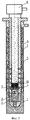
На фиг.1 показано устройство в транспортном положении в условиях скважины (профильный разрез); на фиг.2 - устройство в процессе промывки скважины; на фиг.3 - устройство после перфорации обсадной колонны.Figure 1 shows the device in the transport position in the conditions of the well (profile section); figure 2 - the device in the process of flushing the well; figure 3 - device after perforation of the casing.
Устройство содержит башмак 1, башмачный патрубок 2, обратный клапан 3, стоп-кольцо 4, гидромеханические центраторы-якоря 5, обсадную колонну 6, пружинные центраторы 7, цементировочную головку 8 с двумя цементировочными пробками, то есть с нижней 9 и верхней 10 цементировочными пробками.The device comprises a shoe 1, a
Устройство для осуществления цементирования обсадной колонны работает следующим образом.A device for cementing a casing string is as follows.
После подготовки ствола скважины спускают в него обсадную колонну 6 с элементами ее технологической оснастки. На верхней трубе обсадной колонны 6 монтируют цементировочную головку 8 с установленными двумя цементировочными пробками и ствол скважины промывают.After preparing the wellbore,
В начале процесса промывки скважины во внутреннюю полость обсадной колонны сбрасывают нижнюю цементировочную пробку 9. Нижняя цементировочная пробка 9 проталкивается вниз по колонне 6 промывочной жидкостью и, дойдя до стоп-кольца 4 в колонне 6, останавливается.At the beginning of the flushing process, the
Давление в полости колонны 6 повышается, так как закачка промывочной жидкости продолжается. При этом под действием разности перепада давления над нижней цементировочной пробкой 9 и под ней создается растягивающая сила на нижний конец обсадной колонны и в то же время срабатывают последовательно сверху вниз гидромеханические центраторы-якоря 5, установленные на колонне 6. В процессе срабатывания гидромеханических центраторов-якорей 5, обсадная колонна 6 в местах их установки заякоривается за стенки скважины и центрируется относительно оси скважины.The pressure in the cavity of the
При этом гидромеханические центраторы-якоря 5, установленные на колонне 6, создают затухающие поперечные колебания обсадной колонны 6, что способствует разрушению застойных зон в кольцевом пространстве между стенками скважины и обсадной колонны.At the same time, hydromechanical centralizers-anchors 5 installed on the
В дальнейшем с увеличением разности давления над нижней цементировочной пробкой 9 и под ней мембрана в пробке 9 разрушается и промывочная жидкость через проходной канал в пробке 9 и отверстия в башмаке 1 и башмачном патрубке 2 вытесняется в заколонное пространство скважины.Subsequently, with an increase in the pressure difference above the lower
После окончания промывки скважины вслед за промывочной жидкостью закачивают в колонну необходимое количество цементного раствора и сбрасывают верхнюю цементировочную пробку 10. Вслед за верхней цементировочной пробкой 10 закачивают продавочную жидкость, которой продавливают цементный раствор в затрубное пространство.After flushing the well, after the flushing fluid, the required amount of cement mortar is pumped into the column and the
Подсчитывают количество продавочной жидкости, закачиваемой в скважину. Когда остается 1-2 м3 продавочной жидкости, интенсивность ее закачки снижают. Процесс ведут до схождения пробок 9 и 10, то есть посадки верхней пробки 10 на нижнюю 9. Резкий рост давления на устье служит сигналом для прекращения нагнетания продавочной жидкости в колонну 6.Count the amount of squeeze fluid injected into the well. When 1-2 m 3 of squeezing liquid remains, the intensity of its injection is reduced. The process is carried out until the convergence of
После этого величину давления в колонне 6 повышают выше давления "стоп" или до давления опрессовки и обсадную колонну 6 оставляют под избыточным внутренним давлением. Если по истечении определенного времени величина давления на устье не изменилась, то колонна считается герметичной.After that, the pressure in the
В герметичной колонне 6 стравливают избыточное давление и оставляют ее в таком состоянии до образования цементного камня за колонной.In an
После образования кольца цементного камня за колонной проводят перфорацию обсадной колонны 6, цементного камня и породы для создания гидродинамической связи скважины с пластом. При этом часть ударной энергии поглощается стенками скважины через рычаги гидромеханических центраторов-якорей 5, установленных за зоной перфорации.After the formation of the ring of cement stone behind the string, the
Исключение застойных зон в заколонном пространстве в процессе промывки скважины способствует увеличению степени полноты замещения промывочной жидкости цементным раствором, что ведет к получению более качественного цементного камня.The exclusion of stagnant zones in the annulus during the flushing of the well increases the degree of completeness of the replacement of the flushing fluid with cement mortar, which leads to a better cement stone.
Натянутое состояние обсадной колонны в процессе промывки ствола скважины и цементирования скважины обеспечит получение более равномерного по толщине кольца цементного камня на всей длине цементированного участка обсадной колонны.The tightened state of the casing during the washing of the wellbore and cementing the well will provide a more uniform cement stone in thickness along the entire length of the cemented section of the casing.
Расположение гидромеханических центраторов-якорей 5 за зоной перфорации обеспечивает снижение степени разрушения кольца цементного камня за зоной перфорации, так как они при якорении колонны за стенки скважины являются дополнительными каналами для отвода части ударной энергии в горную породу.The location of the hydromechanical centralizers-anchors 5 behind the perforation zone ensures a decrease in the degree of destruction of the cement stone ring behind the perforation zone, since they, when anchoring the column behind the borehole walls, are additional channels for diverting part of the impact energy into the rock.
Таким образом, получение более качественного цементного камня, более равномерного по толщине кольца цементного камня на участке цементирования ствола скважины и уменьшения степени разрушения кольца цементного камня за зоной перфорации дают возможность повысить качество крепления стенок скважины.Thus, obtaining a better cement stone, more uniform in thickness of the cement stone ring at the cementing section of the wellbore and reducing the degree of destruction of the cement stone ring behind the perforation zone, makes it possible to improve the quality of the fastening of the well walls.
Источник информацииThe source of information
1. Булатов А.И. Тампонажные материалы и технология цементирования скважины: Учеб. для техникумов. - 4-е изд., перераб. и доп. - М.: Недра, 1991.- 9-11 с.1. Bulatov A.I. Grouting materials and well cementing technology: Textbook. for technical schools. - 4th ed., Revised. and add. - M .: Nedra, 1991 .- 9-11 p.
Claims (2)
Priority Applications (1)
| Application Number | Priority Date | Filing Date | Title |
|---|---|---|---|
| RU2005106785/03A RU2299309C2 (en) | 2005-03-09 | 2005-03-09 | Cementing device and method for casing pipe with two cementing plugs |
Applications Claiming Priority (1)
| Application Number | Priority Date | Filing Date | Title |
|---|---|---|---|
| RU2005106785/03A RU2299309C2 (en) | 2005-03-09 | 2005-03-09 | Cementing device and method for casing pipe with two cementing plugs |
Publications (2)
| Publication Number | Publication Date |
|---|---|
| RU2005106785A RU2005106785A (en) | 2006-08-20 |
| RU2299309C2 true RU2299309C2 (en) | 2007-05-20 |
Family
ID=37060352
Family Applications (1)
| Application Number | Title | Priority Date | Filing Date |
|---|---|---|---|
| RU2005106785/03A RU2299309C2 (en) | 2005-03-09 | 2005-03-09 | Cementing device and method for casing pipe with two cementing plugs |
Country Status (1)
| Country | Link |
|---|---|
| RU (1) | RU2299309C2 (en) |
Citations (4)
| Publication number | Priority date | Publication date | Assignee | Title |
|---|---|---|---|---|
| US4949788A (en) * | 1989-11-08 | 1990-08-21 | Halliburton Company | Well completions using casing valves |
| RU2009309C1 (en) * | 1991-02-07 | 1994-03-15 | Мирсат Мирсалимович Нагуманов | Hydromechanical anchor |
| RU2054527C1 (en) * | 1992-11-30 | 1996-02-20 | Вениамин Дмитриевич Куртов | Method for well casing |
| RU2169251C1 (en) * | 1999-12-08 | 2001-06-20 | ОАО "ГАЗПРОМ" ООО "Астраханьгазпром" | Method of casing string hanging |
-
2005
- 2005-03-09 RU RU2005106785/03A patent/RU2299309C2/en not_active IP Right Cessation
Patent Citations (4)
| Publication number | Priority date | Publication date | Assignee | Title |
|---|---|---|---|---|
| US4949788A (en) * | 1989-11-08 | 1990-08-21 | Halliburton Company | Well completions using casing valves |
| RU2009309C1 (en) * | 1991-02-07 | 1994-03-15 | Мирсат Мирсалимович Нагуманов | Hydromechanical anchor |
| RU2054527C1 (en) * | 1992-11-30 | 1996-02-20 | Вениамин Дмитриевич Куртов | Method for well casing |
| RU2169251C1 (en) * | 1999-12-08 | 2001-06-20 | ОАО "ГАЗПРОМ" ООО "Астраханьгазпром" | Method of casing string hanging |
Non-Patent Citations (1)
| Title |
|---|
| БУЛАТОВ А.И. Тампонажные материалы и технология цементирования скважины. - М.: Недра, 1991, с.9-11. * |
Also Published As
| Publication number | Publication date |
|---|---|
| RU2005106785A (en) | 2006-08-20 |
Similar Documents
| Publication | Publication Date | Title |
|---|---|---|
| DK179865B1 (en) | Annular barrier and annular barrier system and method | |
| US4184790A (en) | Submerged pile grouting | |
| CA2557830C (en) | A method and a device for sealing a void incompletely filled with a cast material | |
| RU2086752C1 (en) | Method for back-cementation of casing string in well | |
| US8479818B2 (en) | Method and apparatus to cement a perforated casing | |
| US20110067865A1 (en) | Equipment for remote launching of cementing plugs | |
| RU2320844C2 (en) | Method for pipe spool installation in well | |
| CN102365419A (en) | Expansion against cement for zonal isolation | |
| RU2618249C1 (en) | Method of interval productive formation treatment in open horizontal bore of well | |
| CN109025897B (en) | An in-well foaming volume plugging device | |
| RU2081296C1 (en) | Method and device for strengthening bottom-hole zone of gas wells | |
| RU2299309C2 (en) | Cementing device and method for casing pipe with two cementing plugs | |
| RU2612167C1 (en) | Valve for casing strings | |
| RU2615188C1 (en) | Well stage cementing method | |
| RU2164288C1 (en) | Gear to isolation of strata in well | |
| RU2293838C2 (en) | Casing column cementation method and device for realization thereof | |
| CN207701111U (en) | Oil well pump is anchored bleeder | |
| RU2710577C1 (en) | Method of installing a cement plug for driving unstable rocks when drilling a well | |
| RU2305173C2 (en) | Method and device for production string sealing during sandy well flushing | |
| RU2480575C1 (en) | Method of propping of roof of bottomhole formation zone | |
| RU2354804C1 (en) | Method for well repair | |
| SU1379451A1 (en) | Arrangement for cementing casing in well | |
| RU2562306C1 (en) | Method of isolation of thief zone during well drilling | |
| RU2296209C1 (en) | Method for isolation of formation water inflow in well | |
| SU1689591A1 (en) | Device for mounting of separating bridge |
Legal Events
| Date | Code | Title | Description |
|---|---|---|---|
| MM4A | The patent is invalid due to non-payment of fees |
Effective date: 20090310 |